SP Scientific FTS Systems BioCool 80 User manual

LOW-TEMPERATURE BATH OPERATOR’S MANUAL
FTS
S
YSTEMS
B
IO
C
OOL
™
80
Controlled Rate Freezing Bath


Rev 002, 08/12 i
© SP Scientific 2012
Copyright © 2012 SP Scientific. All marks herein are used under license.
All brand or product names mentioned may be trademarks or registered trademarks of their respective
companies.
Part Number 100006071
Rev 002, 08/12
Original Instructions
The U.S. English version of this document is the original instructions.
All other languages are a translation of the original instructions.
SP Scientific
3538 Main Street
935 Mearns Road
815 State Route 208
Stone Ridge, NY 12484
USA
Warminster, PA 18974
USA
Gardiner, NY 12525
USA
(800) 251-1531
(800) 523-2327
(800) 431-8232
(845) 687-0071
(215) 672-7800
(845) 255-5000
SP Service
(877) 548-4666
SP Service Fax
(845) 687-0024
Website
http://www.spscientific.com/
This Low-Temperature Bath Operator’s Manual contains confidential and proprietary information of SP
Scientific and may be used only by a recipient designated by and for purposes specified by SP Scientific.
Reproduction of, dissemination of, modifications to, or the creation of derivative works from this Low-
Temperature Bath Operator’s Manual, by any means and in any form or manner, is expressly prohibited,
except with the prior written permission of SP Scientific. Permitted copies of this document must retain all
proprietary notices contained in the original.
The information in this document is subject to change without prior notice. Always confirm with SP
Scientific that you are using the most current version of this document. SP Scientific is free to modify any
of its products and services, in any manner and at any time, notwithstanding the information contained in
this document.
THE CONTENTS OF THIS DOCUMENT SHALL NOT CONSTITUTE ANY WARRANTY OF ANY KIND,
EITHER EXPRESSED OR IMPLIED, INCLUDING BUT NOT LIMITED TO THE IMPLIED WARRANTIES
OF MERCHANTABILITY AND/OR FITNESS FOR A PARTICULAR PURPOSE OR GIVE RISE TO ANY
LIABILITY OF SP SCIENTIFIC, ITS AFFILIATES OR ITS SUPPLIERS.
The terms and conditions governing the use of this Low-Temperature Bath Operator’s Manual shall
consist of those set forth in written agreements with SP Scientific.

ii Rev 002, 08/12
© SP Scientific 2012
Important Symbols
WARNING! INJURY OR EVEN
DEATH MAY RESULT IF A
RECOMMENDATION MARKED
WITH THIS SYMBOL IS NOT
HEEDED.
CRUSH HAZARD. KEEP HANDS
CLEAR WHEN OPERATING DOOR.
ELECTRIC SHOCK DANGER!
USE APPROPRIATE CAUTION
TO AVOID INJURY OR DEATH.
CORROSIVE CHEMICAL. WEAR
SUITABLE GLOVES, SAFETY
GLASSES, AND PROTECTIVE
CLOTHING.
BURN DANGER! POTENTIALLY
HOT SURFACE. USE
APPROPRIATE CAUTION.
PROPERTY CAUTION! TO PREVENT
DAMAGE TO CHAMBER EQUIP-
MENT AND/OR LOAD, ADHERE TO
PROCEDURES MARKED BY THIS
SYMBOL.
DO NOT STORE FLAMMABLE
MATERIALS IN CHAMBER.
PRACTICAL OPERATING TIP.
THESE RECOMMENDATIONS
STREAMLINE UNIT OPERATION
AND PREVENT COMMON
OPERATOR ERRORS.
WEAR SAFETY GLASSES.
EXPLOSIVE MATERIALS HAZARD!
KEEP OBJECTS AWAY FROM HEAT.
Safety Warnings
Always transport the unit with care. Sudden jolts or drops may damage the refrigeration system.
Always observe all warning labels.
Always turn off the unit and disconnect the line cord from the available power source prior to performing any
service or maintenance procedures.
Always turn off the unit and disconnect the line cord from the available power source prior to moving the unit.
Always empty the reservoir / bath chamber prior to moving the unit.
Never operate equipment with damaged line cords.
Never operate the unit without cooling fluid in the reservoir.
Never remove warning labels.
Never operate damaged or leaking equipment.

Rev 002, 08/12 iii
© SP Scientific 2012
Warranty Information
FTS Systems BioCool™ 80 low temperature baths are warranted by SP Scientific to be free of defects in material and
workmanship when operated under normal conditions as specified in the instructions provided in this manual. Please
take this opportunity to locate the serial tag on your new FTS Systems BioCool™ 80 and record the information below
for future reference. SP Scientific also recommends that you complete and return your unit’s warranty registration card.
Model Number
Serial Number
Part Number
Limited Warranty
SP Scientific (the “Company”) shall warrant each of its products against defects in material or workmanship for a period
of 12 months from the date of shipment provided that the product is used in a reasonable manner under appropriate
conditions and consistent with the applicable operating instructions.
The obligation of the Company shall be, at its option, to repair or replace, without charge any parts that prove to be
defective within the warranty period, if the purchaser notifies the Company promptly in writing of such defect. No
product shall be returned to the Company without prior approval of the Company.
This limited warranty shall cover the costs of parts and labor to repair or replace all defective product(s) at the Seller’s
factory. For all products installed by the Company and located within the Company service travel areas, this warranty
shall cover transportation charges to ship the product to and from the Company’s factory and/or the costs of travel,
room and board if the Company’s employees conduct repair at the Buyer’s location. In lieu of repair or replacement at
the Company’s factory, the Company may, in its discretion, authorize a third party to perform the repair or replacement
at the Buyer’s location, and at the Company’s sole expense.
The Company shall not be responsible for labor charges payable with respect to persons other than Company
employees. Replacement or repair of parts pursuant to this warranty shall not in any way extend the original warranty
period. The Company shall not be responsible for any unauthorized repairs, replacements or product modifications, nor
will it be responsible for any product failures resulting from such unauthorized repairs, replacements or product
modifications negligently or otherwise made by persons other than Company employees or authorized representatives
of the Company. The buyer shall assume transportation charges to ship the product to and from the Company’s factory
and the costs of travel, room and board if the Company’s employees conduct repair at the Buyer’s location within the
warranty period if the product was not installed by the Company’s and/or is not located within the Company’s service
travel areas.
THE COMPA
NY DOES NOT MAKE AND EXPRESSLY DISCLAIMS ANY WARRANTY OF MERCHANTABILITY OR
FITNESS FOR A PARTICULAR PURPOSE OR ANY OTHER WARRANTY, EXPRESSED OR IMPLIED, WITH
RESPECT TO THE SALE, INSTALLATION, DESIGN OR USE OF ITS PRODUCTS. ADDITIONALLY, THE
COMPANY SHALL
NOT BE LIABLE FOR ANY CONSEQUENTIAL DAMAGES RESULTING FROM THE USE OF OR
ANY DEFECTS IN ITS PRODUCTS.
The Company’s employees are available to provide general advice to customers concerning the use of the Company’s
products; however, oral representations are not warranties with respect to particular products or their uses and may not
be relied upon if they are inconsistent with the relevant product specifications for the items set forth herein.
Notwithstanding the above, the terms and conditions set forth in the Company’s formal sales contracts shall be
controlling and supersede any inconsistent terms contained herein, and any changes to such contracts must be made
in writing and signed by an authorized executive of the Company.
WARNING! THE DISPOSAL AND/OR EMISSION OF SUBSTANCES USED IN CONNECTION WITH
THIS EQUIPMENT MAY BE GOVERNED BY VARIOUS FEDERAL, STATE OR LOCAL
REGULATIONS. ALL USERS OF THIS EQUIPMENT ARE URGED TO BECOME FAMILIAR WITH
ANY REGULATIONS THAT APPLY IN THE USERS AREA CONCERNING THE DUMPING OF
WASTE MATERIALS IN OR UPON WATER, LAND OR AIR AND TO COMPLY WITH SUCH
REGULATIONS.

iv Rev 002, 08/12
© SP Scientific 2012

Rev 002, 08/12 v
© SP Scientific 2012
Contents
Important Symbols ............................................................................................................................................... ii
Safety Warnings................................................................................................................................................... ii
Warranty Information .......................................................................................................................................... iii
Introduction ................................................................................................................. 1
Overview ..............................................................................................................................................................1
Key Features ...................................................................................................................................................1
Maximum Cooling Rates .................................................................................................................................2
BioCool™ 80 Overview........................................................................................................................................2
Buzzer .............................................................................................................................................................3
Installation................................................................................................................... 5
Initial Inspection ...................................................................................................................................................5
Installation............................................................................................................................................................6
Air Flow Considerations...................................................................................................................................6
Ambient Conditions .........................................................................................................................................6
Services and Utilities .......................................................................................................................................6
Installing the Magnetic Stirrer and Vortex Breaker ..........................................................................................7
Operation .................................................................................................................... 9
Overview ..............................................................................................................................................................9
Operation .............................................................................................................................................................9
Powering On....................................................................................................................................................9
The Solo Controller .......................................................................................................................................10
Display and Indicators ...................................................................................................................................10
Adjusting Bath Temperature..........................................................................................................................10
Ramp / Soak Patterns ...................................................................................................................................11
Magnetic Stirrer .............................................................................................................................................15
Powering Off..................................................................................................................................................15
Restarting...........................................................................................................................................................15
Fluid .......................................................................................................................... 17
Recommended Fluid and Selected Properties...................................................................................................17
Fluid Filling.........................................................................................................................................................17
Magnetic Stirrer .............................................................................................................................................18
Maintenance ............................................................................................................. 19
Cleaning.............................................................................................................................................................19

Contents
FTS Systems BioCool™ 80
vi Rev 002, 08/12
© SP Scientific 2012
Condenser.....................................................................................................................................................19
Bath System ..................................................................................................................................................19
Compressor Safeties .........................................................................................................................................20
Refrigerant Types and Properties..................................................................................................................20
Refrigeration System.....................................................................................................................................20
Voltage ..........................................................................................................................................................20
Accessories............................................................................................................... 21
Straw Rack (Model SR-36) ................................................................................................................................21
Ampule Rack (Model SR-12) .............................................................................................................................21
Ampule Rack (Model SR-15) .............................................................................................................................22
Appendix A: Temperature Calibration ....................................................................... 23
Appendix B: Troubleshooting .................................................................................... 25

Rev 002, 08/12 1
© SP Scientific 2012
Chapter
1
Introduction
Overview
The FTS Systems BioCool™ 80 delivers controlled rate freezing capabilities, as well
as continuous operation at temperatures as low as -80 °C. Built to provide you with
years of smooth, quiet and reliable operation, the FTS Systems BioCool™ 80 packs
both performance and innovation into a compact, bench-top design.
Utilizing a liquid medium, the FTS Systems BioCool™ 80 controls the rate of freezing
samples without the use of expendables such as dry ice or liquid nitrogen (N2(liq)).
The FTS Systems BioCool™ 80 comes standard with temperature control and also
includes a variable speed-controlled magnetic stirrer to provide more accurate
temperature control and uniformity. Each configuration features an air-cooled
refrigeration system and stainless steel reservoir.
THE FLUID AND INNER WALLS OF THE RESERVOIR CAN REACH
TEMPERATURES BELOW -90 °C (-130 °F). EXTREMELY LOW TEMPERATURES
CAN CAUSE SERIOUS AND IMMEDIATE DAMAGE TO SKIN. THE ABSENCE OF
FROST IN UNITS EQUIPPED WITH THE FROST ISOLATING WARMING LOOP
SHOULD NOT BE MISTAKEN AS AN INDICATION OF WARM TEMPERATURE.
DESPITE THE ABSENCE OF FROST, THE TEMPERATURE OF THE RESERVIOR
FLUID AND WALLS MAY BE DANGEROUSLY LOW.
THE FTS SYSTEMS BIOCOOL™ 80 IS NOT INTENDED FOR USE WITH
EXTREMELY FLAMMABLE FLUIDS SUCH AS ISOPENTANE (C5H12).
Key Features
Specimen chamber is 5 inches (12.7 cm) in diameter and 6 inches (15.2 cm)•
deep.
Magnetic stirrer and vortex breaker allow for constant agitation of bath.•
Optional racks allow for the use of straws or ampules.•
Introduction
FTS Systems BioCool™ 80
2 Rev 002, 08/12
© SP Scientific 2012
Maximum Cooling Rates
The following cooling rates are achieved with ambient conditions of 22 ºC (72 ºF)
using clean methanol as the bath fluid. Some deviation from these rates may occur if
the ambient temperature is significantly higher or lower than 22 ºC (72 ºF), if the
methanol bath fluid is contaminated by water or if a different bath fluid is used.
Temperature Range Cooling Rate
20 to -60 ºC 2.5 ºC/minute
-60 to -80 ºC 1.3 ºC/minute
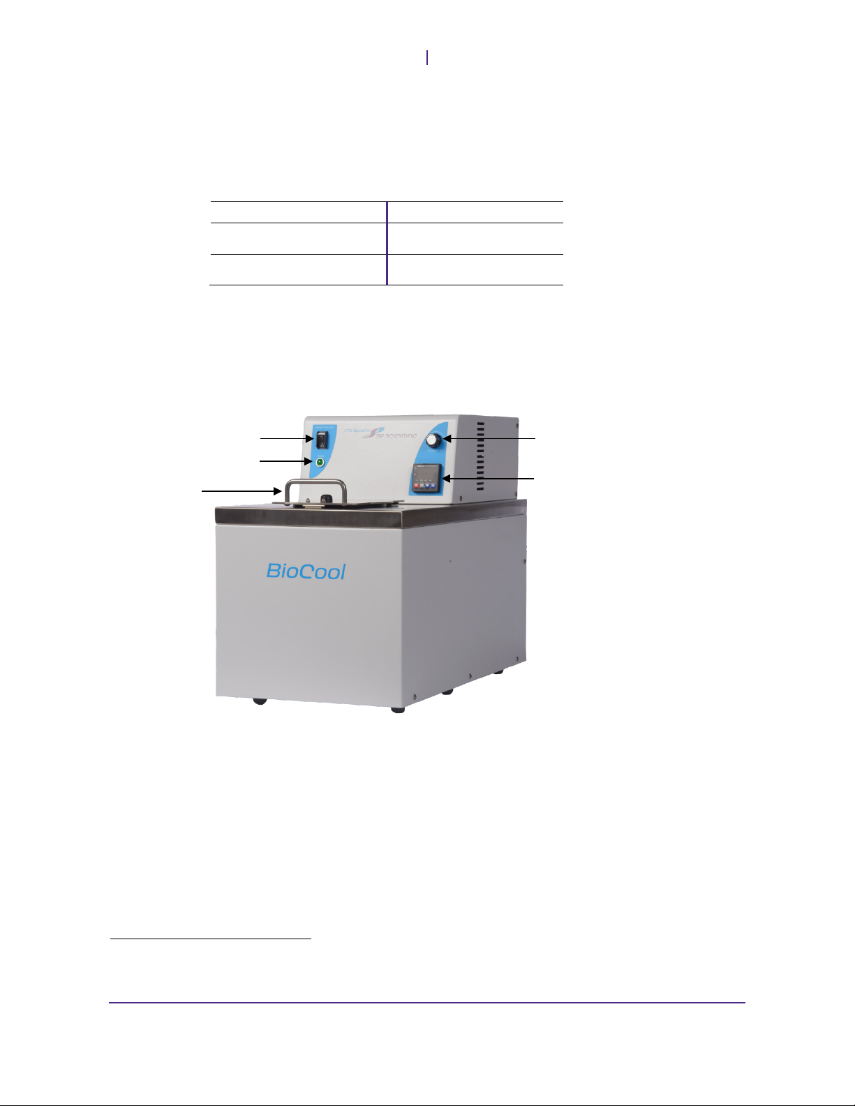
BioCool™ 80 Overview
The FTS BioCool™ 80 is designed for general freezing applications. This unit includes
a cascade refrigeration system and an on/off breaker switch. The BioCool™ also
features the Solo microprocessor controller, which provides precise temperature
control within ± 0.1 °C across the temperature control range of -80 °C to 20 °C. 1
When powered on, the BioCool™ 80’s refrigeration system will activate. After
approximately two (2) minutes, the green Chill light illuminates to indicate that the
second stage compressor is active.
The FTS BioCool™ 80 is also equipped with a solid-state variable speed-controlled
magnetic stirrer to provide more accurate temperature control and uniformity.
1The FTS Systems BioCool™ 80 offers continuous operation at temperatures as low as -80 °C. Lowest possible temperatures
may be dependent upon the selected bath fluid, as well as ambient conditions and airflow.
Breaker Switch
Chill Indicator LED
Hinged, Stainless
Steel Insulated
Reservoir Lid
Fluid Stir Control Dial
Solo Microprocessor Controller

FTS Systems BioCool™ 80
Introduction
Rev 002, 08/12 3
© SP Scientific 2012
Buzzer
The FTS BioCool™ 80 comes equipped with a buzzer, which is located on the back of
the unit. The buzzer will sound at the end of a program run, notifying the operator that
the run has completed.
Note: For additional information about the buzzer, including how to program a run and silence
the buzzer, please see SP Scientific’s Solo Controller operator’s manual.
Buzzer

Introduction
FTS Systems BioCool™ 80
4 Rev 002, 08/12
© SP Scientific 2012

Rev 002, 08/12 5
© SP Scientific 2012
Chapter
2
Installation
Initial Inspection
Your FTS Systems BioCool™ 80 low-temperature bath was carefully packed and
thoroughly inspected before leaving the SP Scientific factory. However, in the unlikely
event that shipping damage has occurred, retain all packing material and contact your
freight carrier immediately.
DO NOT ACCEPT DAMAGED SHIPMENTS FROM A CARRIER WITHOUT A
SIGNED NOTIFICATION OF DAMAGES.
Upon receiving your shipment, inspect all contents of your equipment for damage.
Uncrate and/or unwrap the unit. Carefully remove all packing material from the unit
and inspect for visible damage. Check packing material for small accessory items and
retain shipping carton and packing material if possible. Inspect the inside of the unit
and related parts for visible damage and leaks. Check for visible liquid at or near the
base of the unit. The reservoir should be clean and dry.
If concealed damage or loss is discovered, contact the freight carrier immediately.2
Keep all contents, packing material and related paperwork intact until a written report
is obtained.
Note: SP Scientific will cooperate in the matter of collecting your claim, but is not responsible
for the collection or free replacement of the material. When possible, replacement parts will be
shipped and invoiced to you, making them a part of your claim.
2“Concealed damage or loss” refers to damage or loss that does not become apparent until the merchandise has been
unpacked and inspected. Should damage or loss be discovered, you may make a written request for inspection by the carrier's
agent within 15 days of the delivery date. You may then file a claim with the freight carrier or SP Scientific, depending on the
terms of your shipment. If your shipment was “FOB Destination” file your claim with SP Scientific and include the inspection
report and any other supporting documents. If your shipment was “FOB Shipping Point” file your claim with the freight carrier
and include the inspection report and any other supporting documents.
Installation
FTS Systems BioCool™ 80
6 Rev 002, 08/12
© SP Scientific 2012
Installation
The FTS Systems BioCool™ 80 is designed for bench-top installation in a laboratory
environment. The unit should be installed on a firm, level surface in a location that is
convenient for both operation and service.
NEVER PLACE THE UNIT IN AN AREA WHERE EXCESSIVE HEAT, MOISTURE OR
CORROSIVE MATERIALS ARE PRESENT.
Air Flow Considerations
The FTS Systems BioCool™ 80 is equipped with an air-cooled refrigeration system.
Air is pulled from the left side of the unit to cool the refrigeration system components
and then exits the rear panel. When positioning your system, ensure that it is located
on a firm, level surface in an area that provides adequate air circulation.
Inadequate airflow will degrade the unit’s cooling capacity and in extreme cases may
result in compressor failure. A minimum of four (4) inches of clearance on all sides of
the unit is required to ensure proper airflow and avoid damage to the refrigeration
system.
Ambient Conditions
For best low-temperature operation, consider that the ideal ambient temperature for
your FTS Systems BioCool™ 80 is approximately 22 °C (72 °F). Higher ambient
temperatures will interfere in the system’s ability to achieve its ultimate low
temperature.
NEVER OPERATE THE FTS SYSTEMS BIOCOOL™ 80 IN AN AREA WITH AN
AMBIENT TEMPERATURE ABOVE 32°C (90°F).
Services and Utilities
The FTS Systems BioCool™ 80’s serial tag, which is located on the unit’s back panel,
provides the unit’s serial number and electrical requirements. Ensure that the voltage,
phase, frequency and amperage listed on the serial tag match your facility’s available
power supply (e.g., as a minimum the power outlet you intend to use must meet the
requirements listed on the serial tag).
CAUTION! IF YOU ARE UNSURE ABOUT THE AVAILABLE ELECTRICAL VOLTAGE
SUPPLY IN YOUR FACILITY, CONSULT A QUALIFIED ELECTRICIAN.
Prior to connecting your FTS Systems BioCool™ 80 to the available electrical supply,
ensure that the Main Power switch is in the Off position. You may connect the unit to
the available electrical supply at this time.

FTS Systems BioCool™ 80
Installation
Rev 002, 08/12 7
© SP Scientific 2012
Installing the Magnetic Stirrer and Vortex Breaker
The FTS BioCool™ 80 is equipped with a solid-state variable speed-controlled
magnetic stirrer and a vortex breaker to provide more accurate temperature control
and uniformity. To install the magnetic stirrer and vortex breaker:
Remove the packaging washers from the inside of the stainless steel1.
reservoir and from the bottom of the magnetic stirrer. These washers are
placed on the magnetic components of the unit for shipping purposes only
and are intended to be removed prior to operation.
Place the magnetic stirrer, magnet side down, into the center of the reservoir.2.
(Pushing the edges of the stirring mechanism beyond the black gasket at the
top of the reservoir may require some force.) As you lower the magnetic
stirrer into place, be careful not to bend or tweak the metal temperature probe
that hangs inside the reservoir.
Note: The screws on top of the magnetic stirrer should not come in contact with the
sides of the bath as you place the magnetic stirrer into the reservoir. If they do, retract
them using your fingers or a screwdriver.
Packaging Washer in Reservoir
Packaging Washer on Bottom
of Magnetic Stirrer
Temperature Probe
Reservoir (Top View)
Magnetic Stirrer (Bottom View)

Installation
FTS Systems BioCool™ 80
8 Rev 002, 08/12
© SP Scientific 2012
Once the stirrer assembly is in place, adjust the four holding screws by hand3.
so that each screw lightly touches the side of the reservoir. Then, use a
screwdriver to further extend each screw so that the stirrer is held snugly in
place in the center of the reservoir. Be sure that all screws are extended to
the same length; this will keep the stirrer assembly centered in the bath.
Hold the vortex breaker by its metal handle (a small tab, bent 90° at the tip)4.
and place it into the reservoir so that it rests evenly on top of the magnetic
stirrer. (Pushing the edges of the vortex breaker beyond the black gasket at
the top of the reservoir may require some force.)
Magnetic Stirrer In
Holding Screws
Holding Screws
Temperature Probe
Reservoir (Top View)
Reservoir (Top View)
Magnetic Stirrer and Vortex Breaker
Assembled in Reservoir
Vortex Breaker Handle
Temperature Probe

Rev 002, 08/12 9
© SP Scientific 2012
Chapter
3
Operation
Overview
The FTS BioCool™ 80 offers a continuous display of temperatures in 0.1 degree
increments and is capable of controlling temperatures within ± 0.1 °C across the
equipment’s full operating temperature range.
Operation
Powering On
Note: Before powering on and cooling, install the magnetic stirrer and vortex breaker (as
described in Chapter 2: Installation) and fill the reservoir with fluid (as described in Chapter 4:
Fluid).
To activate the refrigeration system:
Toggle the on/off breaker switch to the On position.1.
Main Breaker

Operation
FTS Systems BioCool™ 80
10 Rev 002, 08/12
© SP Scientific 2012
The Solo Controller
The BioCool™ 80 includes a proportional-integral-derivative (PID) microprocessor
controller. The Solo controller features a bright, two-line, two-color, seven segment
LED readout.
Display and Indicators
Process Value (PV) Display
Displays the current fluid temperature in the bath.
Set Value (SV) Display
Displays the desired fluid temperature.
Adjusting Bath Temperature
Press the Up and/or Down buttons to increase and decrease the fluid1.
temperature shown on the SV Display.
Press the Set button to select the displayed value.2.
Note: For more detailed information on operating the Solo controller, including how to
connect your Solo controller to a PC for ease of operation, see SP Scientific’s Solo
Controller operator’s manual.
Status Indicator Area
Down Button
Up Button
Rotate Button
Set Button
Process Value (PV)
Display
Set Value (SV)
Display

FTS Systems BioCool™ 80
Operation
Rev 002, 08/12 11
© SP Scientific 2012
Ramp / Soak Patterns
The FTS BioCool™ 80 is preprogrammed with three sample ramp/soak patterns.
These patterns can be viewed using either the Solo keypad or the Solo configuration
software. After becoming familiar with the ramp/soak functionality as demonstrated via
the three sample patterns, create new patterns to suit your individual process
requirements using either the Solo keypad or the Solo configuration software. For
more information, refer to SP Scientific’s Solo Controller operator’s manual.
THE THREE SAMPLE PATTERNS THAT COME LOADED ON YOUR BIOCOOL™ 80
WERE DESIGNED FOR DEMONSTRATION PURPOSES. SP SCIENTIFIC DOES NOT
RECOMMEND USING THESE PATTERNS FOR FREEZING TISSUE OR OTHER
PRODUCT-RELATED APPLICATIONS.
When viewed using the Solo software Ramp/Soak Pattern Editor, the three sample
patterns (Pattern 0, Pattern1 and Pattern 2) appear as follows:
Note: Please refer to SP Scientific’s Solo Controller operator’s manual for complete details on
how to operate Ramp/Soak on your FTS BioCool™ 80 and how to download and install the
Solo software on a PC.
Calculating Ramp Rate
The ramp rate can be calculated using the following equation:
Ramp Rate =
Change in Temp
Change in Time

Operation
FTS Systems BioCool™ 80
12 Rev 002, 08/12
© SP Scientific 2012
Sample Pattern 0
Step
Parameter
Value
Step 0
Temp.
22 °C
Time.
10 minutes
Step 1
Temp.
-6 °C
Time.
15 minutes
Step 2
Temp.
-6 °C
Time. 15 minutes
Step 3
Temp.
-40 °C
Time.
1 Hour, 43 minutes
Step 4
Temp.
-40 °C
Time.
10 minutes
Step 5
Temp.
0 °C
Time.
0 minutes
Step 6
Temp.
0 °C
Time.
0 minutes
Step 7 Temp. 0 °C
Time.
0 minutes
Last Step Number
4
Additional Cycles
0
Next Pattern Number
Program End
Sample Pattern 0 Description
The program starts at 22 °C and holds (soaks) at that temperature for 10 minutes. The
temperature then ramps from 22 °C to -6 °C in 15 minutes. This results in a ramp rate
of 1.9 °C/m. A temperature of -6 °C is then held (soaked) for 15 minutes. The
temperature then ramps from -6 °C to -40 °C over the period of 1 hour and 43
minutes. This results in a ramp rate of .33 °C/m. The temperature is then held at
-40 °C for 10 minutes.
Note: The system has been factory programmed to sound an alarm when the programmed
pattern ends.
Sample Pattern 1
Step
Parameter
Value
Step 0
Temp.
22 °C
Time.
10 minutes
Step 1
Temp.
-7 °C
Time.
12 minutes
Step 2
Temp.
-7 °C
Time.
30 minutes
Step 3
Temp.
-33 °C
Time.
52 minutes
Step 4
Temp.
-33 °C
Time.
0 minutes
Table of contents
Other SP Scientific Laboratory Equipment manuals


