Space GA2645. Series User manual

For spare parts drawings refer to the section “ LIST OF COMPONENTS” enclosed to this manual.
• For any further information please contact your local dealer or call:
INSTRUCTION MANUAL
GB TRANSLATION FROM THE
ORIGINAL INSTRUCTIONS
- Rev. n. 0 (03/2017)
7300-M009-0_P
GA2645.XX - GA2645I.XX
GA2645IT.30
GA2645D.XX - GA2645ID.XX
GA2645ITD.30
GA2645V.XX - GA2645IV.XX
GA2645ITV.30
7300-M009-0_P
Technical services: SPACE s.r.l. a s.u. - Via Sangano, 48 - 10090 Trana - Torino Italy

INSTRUCTION, USE AND
MAINTENANCE MANUAL Page 2 of 45 GB
Space s.r.l.
7300-M009-0_P
GA2645 - GA2645D - GA2645V
SUMMARY
SYMBOLS USED IN THE MANUAL AND
ON THE MACHINE________________________ 4
1.0 GENERAL INTRODUCTION __________ 7
1.1 Introduction ____________________________ 7
2.0 INTENDED USE _____________________ 7
2.1 Training of personnel __________________ 7
3.0 SAFETY DEVICES ___________________ 8
3.1 Residual risks __________________________ 8
4.0 GENERAL SAFETY RULES __________ 9
5.0 PACKING AND MOBILIZATION FOR
TRANSPORT _______________________ 10
6.0 UNPACKING ________________________ 10
7.0 MOBILIZATION_____________________ 11
8.0 WORKING ENVIRONMENT CONDI-
TIONS______________________________ 11
8.1 Working position ______________________11
8.2 Installation space _____________________11
8.3 Lighting _______________________________12
9.0 ANCHORING SYSTEM ______________ 12
10.0 ASSEMBLY AND PREPARATION FOR
USE ________________________________ 12
10.1 Assembly procedures _________________12
10.2 Post assembly _________________________12
10.3 Bead breaker arm mounting __________13
10.4 Tubeless inflation mounting (only for
I and IT version) ______________________13
10.5 Electrical connections_________________14
10.6 Direction of rotation of motor (ver-
sions with three phase motor)_________15
10.7 Air connection_________________________15
10.8 Controls _______________________________15
11.0 CONTROLS_________________________ 16
11.1 5 pedals control unit __________________16
11.2 Inflation pedal (on demand) ___________16
11.3 Post handle manual adjustment_______17
12.0 USING THE MACHINE ______________ 17
12.1 Precaution measures during tyre re-
moval and fitting ______________________17
12.2 Preliminary operations - Preparing
the wheel ______________________________17
12.3 Bead breaking_________________________18
12.4 Wheel clamping on the mandrel _______19
12.5 Demounting ___________________________20
12.6 Setting the tool for tyre fitting and
removal _______________________________21
12.6.1 Setting the clamps travel __________21
12.6.2 Setting the tool for tyre fitting
and removal _______________________22
12.7 Adjusting descent of the hexagonal
shaft (on demand) _____________________23
12.8 Mounting the tyre _____________________24
12.9 Tyre inflation__________________________25
12.9.1 Tyre inflation with pressure
gauge (on demand)_________________25
12.9.2 Tubeless tyre inflation device ______25
12.10 Version with pneumatic balancing
(on demand) ___________________________26
12.10.1 Demounting_______________________26
13.0 ROUTINE MAINTENANCE __________ 27
13.1 Lubricants ____________________________28
14.0 TROUBLESHOOTING TABLE _______ 29
15.0 TECHNICAL DATA__________________ 31
15.1 Weight _________________________________31
15.2 Dimensions____________________________32
16.0 STORING___________________________ 34
17.0 SCRAPPING ________________________ 34
18.0 REGISTRATION PLATE DATA ______ 34
19.0 FUNCTIONAL DIAGRAMS __________ 34
Table A - 3 Ph single speed electrical
diagram (GA2645)_________________35
Table B - 3 Ph double speed electrical
diagram (GA2645V) _______________36
Table C - 1 Ph single speed electrical
diagram (Invemotor) (GA2645D) __37
Table D - Electric diagram __________________38
Table E - 110V 1Ph 1 speed electrical
diagram ___________________________39
Table F - 1 Ph single speed electrical
diagram ___________________________40
Table G - Pneumatic diagram (GA2645.XX -
GA2645D.XX - GA2645V.XX) ________41
Table H - Pneumatic diagram (G800A68) ____42
Table I - Pneumatic diagram (GA2645I.XX -
GA2645ID.XX - GA2645IV.XX) _______43
Table L - Pneumatic diagram (GA2645IT.XX
- GA2645ITD.XX - GA2645ITV.XX) ___44
Table M - Pneumatic diagram (valid for
version with pressure regulator -
GA2645ID.26) ______________________45
20.0 LIST OF COMPONENTS

INSTRUCTION, USE AND
MAINTENANCE MANUAL
Page 3 of 45
GB
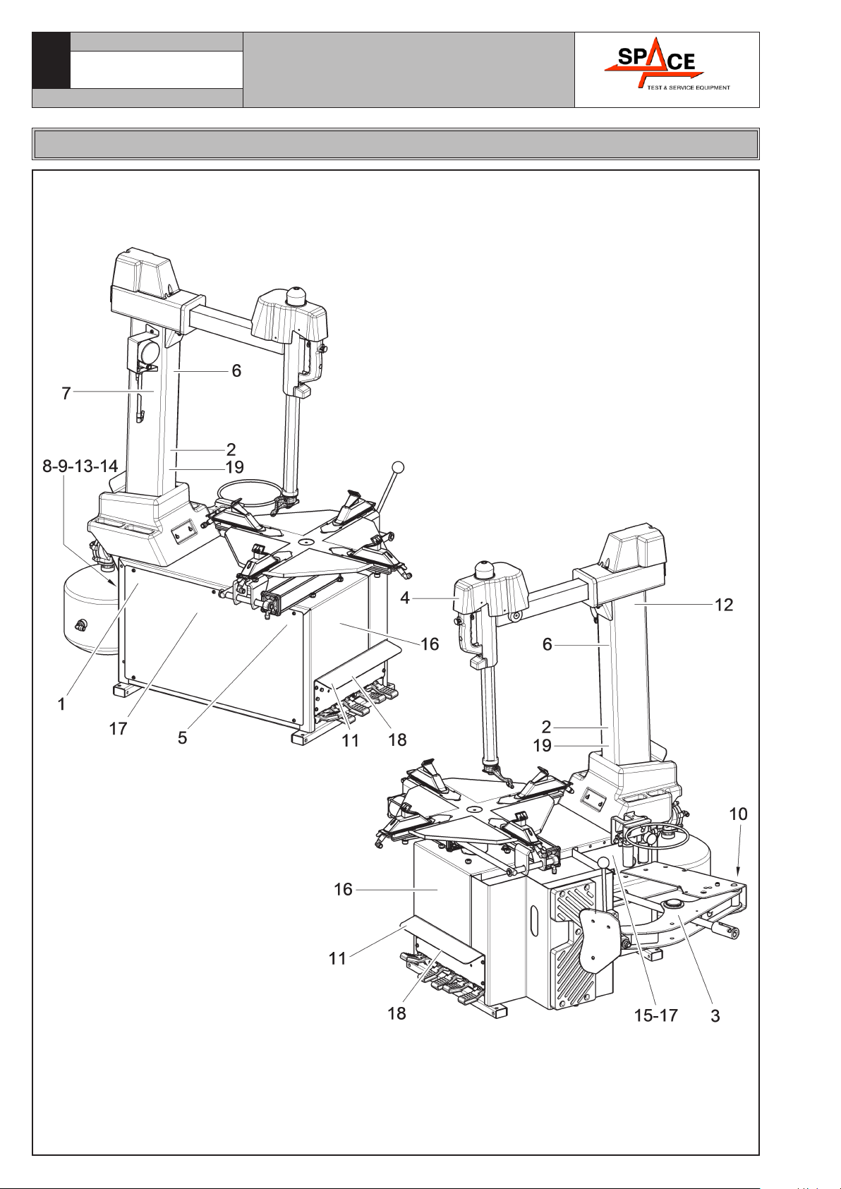
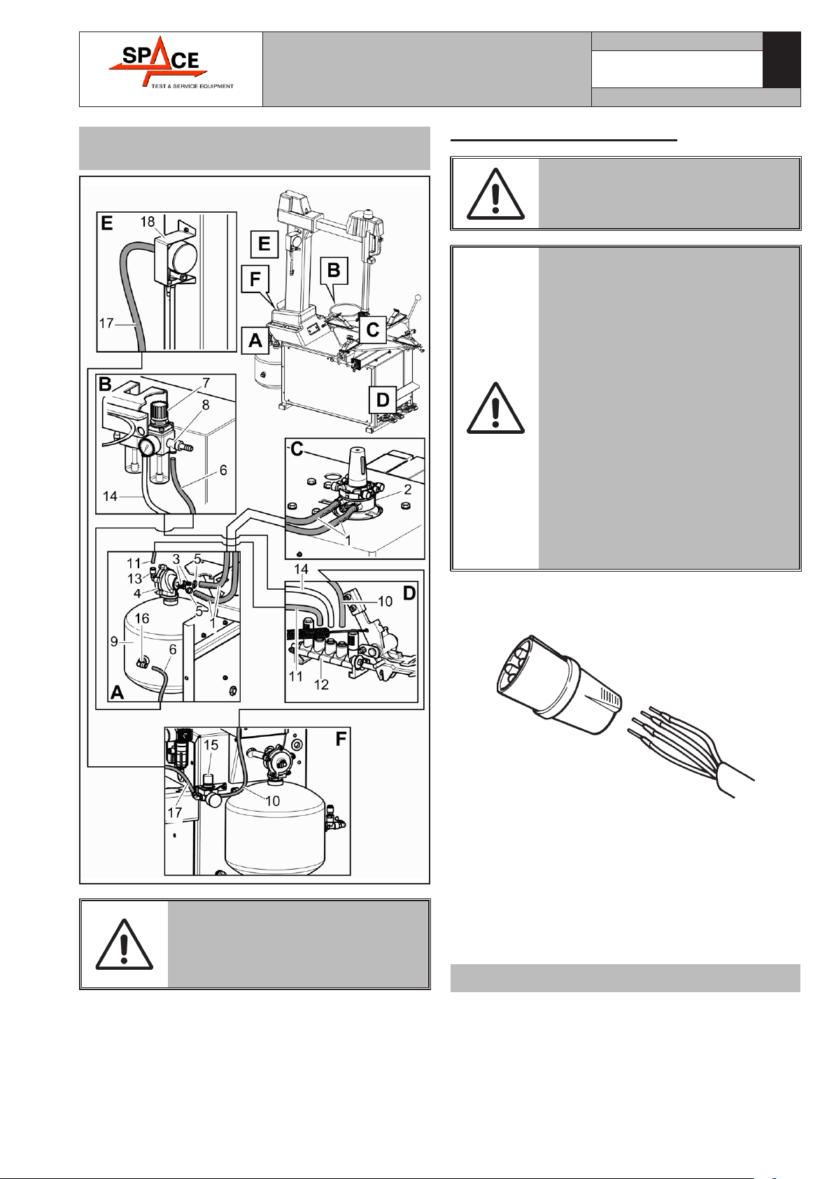
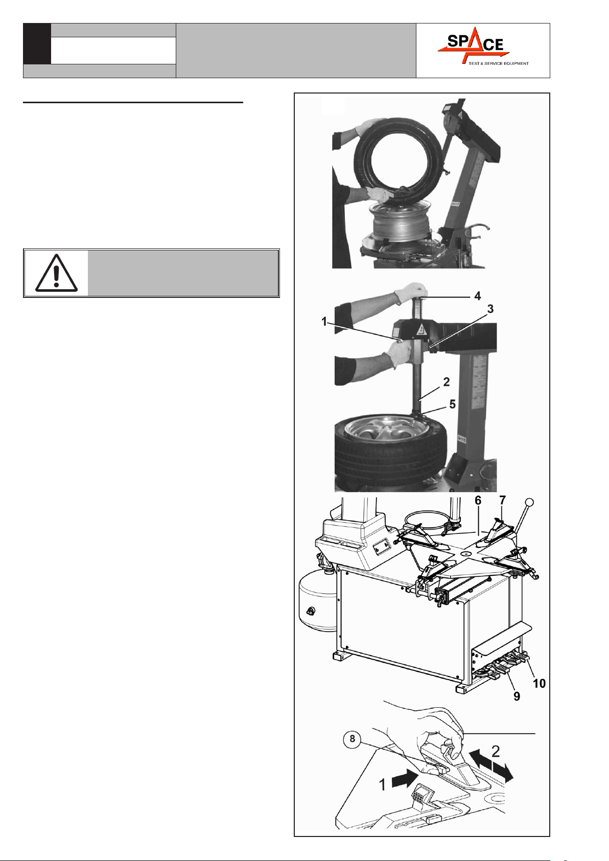
Fig. 1
Space s.r.l.
7300-M009-0_P
GA2645 - GA2645D - GA2645V
KEY
1 – Control pedal
2 – Mandrel
3 – Vertical rod
4 – Horizontal arm
5 – Head
6 – Head shaft and horizontal arm securing/releasing knob push-button
7 – Handle
8 – Vane
9 – Pad
10 – Tyre deflating push-button
11 – Lubricator filter unit
12 – Tubeless inflating device (only for I versions)
13 – Inflation pedal (only for I - IT versions)
14 – Microregulator (valid for version with pressure regulator - GA2645ID.26)
INSTRUCTION, USE AND
MAINTENANCE MANUAL Page 4 of 45 GB
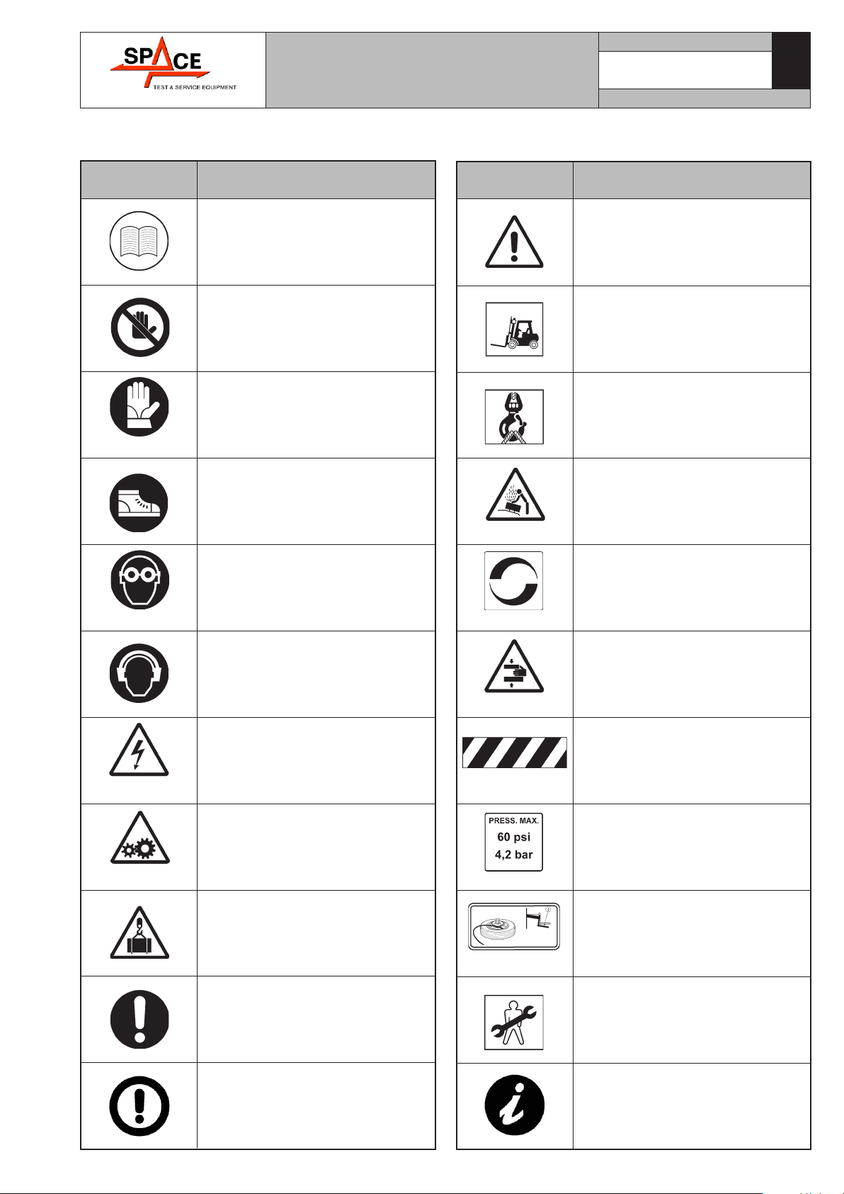
Tyre burst danger.
Spindle rotation direction.
Hands crushing danger.
General danger.
Max inflation pressure rating.
Inflation pedal.
Technical assistance necessary.
Do not perform any intervention.
SYMBOLS USED IN THE MANUAL AND ON THE MACHINE
Symbols Description
Read instruction manual.
FORBIDDEN!
Wear work gloves.
Wear work shoes.
Wear safety earcaps.
99990758
Shock hazard.
999911770
Danger! Moving mechanical parts.
Caution: hanging loads.
Mandatory. Operations or jobs to
be performed compulsorily.
Danger! Be particularly careful.
Symbols Description
Move with fork lift truck or pallet
truck.
Lift from above.
Wear safety goggles.
Warning. Be particularly careful
(possible material damages).
Note. Indication and/or useful
information.
Space s.r.l.
7300-M009-0_P
GA2645 - GA2645D - GA2645V
INSTRUCTION, USE AND
MAINTENANCE MANUAL
Page 5 of 45
GB
INFORMATION PLATE LOCATION TABLE
Space s.r.l.
7300-M009-0_P
GA2645 - GA2645D - GA2645V

INSTRUCTION, USE AND
MAINTENANCE MANUAL Page 6 of 45 GB
Ref. Code Description
1 99990758 Electricity danger plate
2 999910050 Protection device use plate
3 999910060 Bead breaker danger plate
4 999910070 Head danger indicating plate
5 999911770 Unit move indicating plate
6 999911870 Headphones plate
7 999911890 Bursting tyre hazard plate
8999912380 Voltage plate 400V 50Hz 3Ph
999912550 Voltage plate 110/60/1
9 999912390 230V 50 Hz 3 Ph plate
10 999912460 Supply pressure indicating plate
11 999913060 Pedal plate
12 999913280 Column tilting plate
13 999914620 200/265V 50/60Hz 1Ph voltage plate
14 999912530 Valid for 220V 60Hz 1Ph kW0.75 version
15 999916311 Rubbish skip label
16 - Manufacturer nameplate
17 - Serial number plate
18 999921010 5 pedals pedalboard plate
19 B4219000 Rotation indicating plate
999916011 Motoinverter plate
IF ONE OR MORE PLATES DISAPPEAR FROM THE MACHINE OR BECOMES DIFFICULT
TO READ. REPLACE IT AND QUOTE ITS/THEIR CODE NUMBER/S WHEN REORDERING.
Space s.r.l.
7300-M009-0_P
GA2645 - GA2645D - GA2645V

INSTRUCTION, USE AND
MAINTENANCE MANUAL
Page 7 of 45
GB
SOME OF THE PICTURES PRE-
SENT IN THIS MANUAL HAVE
BEEN OBTAINED FROM PICTURES
OF PROTOTYPES, THEREFORE
THE STANDARD PRODUCTION
MACHINES AND ACCESSORIES
CAN BE DIFFERENT IN SOME
COMPONENTS.
1.0 GENERAL INTRODUCTION
This manual is an integral part of the product and
must be retained for the whole operating life of the
machine.
Carefully study the warnings and instructions con-
tained in this manual. It contains important instruc-
tions regarding FUNCTIONING, SAFE USE and
MAINTENANCE.
KEEP THE MANUAL IN A KNOWN,
EASILY ACCESSIBLE PLACE FOR
ALL ACCESSORY OPERATORS
TO CONSULT IT WHENEVER IN
DOUBT.
THE MANUFACTURER DISCLAIMS
ALL RESPONSIBILITY FOR ANY
DAMAGE OCCURRED WHEN THE
INDICATIONS GIVEN IN THIS
MANUAL ARE NOT RESPECTED:
AS A MATTER OF FACT, THE NON-
COMPLIANCE WITH SUCH INDI-
CATIONS MIGHT LEAD TO EVEN
SERIOUS DANGERS.
1.1 Introduction
Thank you for preferring electro-hydraulic tyre-chang-
er. We feel sure you will not regret your decision. The
machine has been designed for use in professional
workshops and in particular it stands out for its reli-
ability, safe and rapid operation: with just a small de-
gree of maintenance and care, this will give you many
years of trouble-free service and lots of satisfaction.
This manual contains all operating instructions and
details on how to service and use the machine correctly.
Space s.r.l.
7300-M009-0_P
GA2645 - GA2645D - GA2645V
2.0 INTENDED USE
The machines of model “GA2645 - GA2645D
- GA2645V” and relevant versions, are car tyre
changers intended for use solely for mounting, de-
mounting and inflating wheels having max. diameter
of 45”- and max. width of 17”.
THIS ACCESSORY MUST ONLY BE
USED FOR THE PURPOSE FOR
WHICH IT IS SPECIFICALLY DE-
SIGNED.
ANY OTHER USE IS CONSIDERED
IMPROPER AND THEREFORE UN-
ACCEPTABLE.
THE MANUFACTURER CANNOT
BE HELD RESPONSIBLE FOR ANY
DAMAGE CAUSED BY IMPROPER,
ERRONEOUS, OR UNACCEPTABLE
USE.
AN INTENSIVE USE OF THE EQUIP-
MENT IN INDUSTRIAL ENVIRON-
MENT IS NOT RECOMMENDED.
2.1 Training of personnel
The machine may be operated only by suitably
trained and authorized personnel.
Given the complexity of the operations necessary to
manage the machine and to carry out the operations
safely and efficiently, the personnel must be trained
in such a way that they learn all the information
necessary to operate the machine as intended by the
manufacturer.
A CAREFUL READING OF THIS
INSTRUCTION MANUAL FOR
USE AND MAINTENANCE AND A
SHORT PERIOD OF TRAINING
WITH SKILLED PERSONNEL CAN
BE AN ENOUGH PREVENTIVE
PREPARATION.
INSTRUCTION, USE AND
MAINTENANCE MANUAL Page 8 of 45 GB
Space s.r.l.
7300-M009-0_P
GA2645 - GA2645D - GA2645V
3.0 SAFETY DEVICES
All the machines are equipped with:
• Fixed guards.
The machine is fitted with a number of fixed guards
intended to prevent potential crushing, cutting and
compression risks.
• “operator attending” controls (immediate stop
by releasing control) for: mandrel rotation, bead
breaker vane motion, inflating; other drives such as
rim clamping on spindle, head clamping cannot be
of the operator-attending type, seen their function. In
these cases safety is guaranteed by compliance with
indications or precautions on machine residual risks
(warning plates) also mentioned in the user’s guide.
Moreover all machines that can be used for inflating
tires (“I” and “IT” versions) are equipped with the fol-
lowing:
• pressure gauge for tyre pressure reading, EC-certified
and in compliance with 86/217/EEC Standard;
• motor protection devices (for GA2645D.XX -
GA2645ID.XX - GA2645ITD.30 models). The new
“Invemotor” motor is equipped with electronic
protection devices. They stop the motor if working
defected conditions appear to avoid that the motor
itself can be damaged and that the operator safety
can be compromised (overvoltage, overload, over-
temperature). For other details, see the chapter 14
“Fault-Finding”.
• Max. pressure valve fitted on compressed air reser-
voir (preset – see pneumatic diagram) in compliance
with 87/404/EEC Standard;
• Non-adjustable (balancing valve) pressure limiter.
This allows inflation of tyres in reasonable safety.
Inflation of tyres to over 4,2 ± 0,2 bar (60 PSI) is
not allowed.
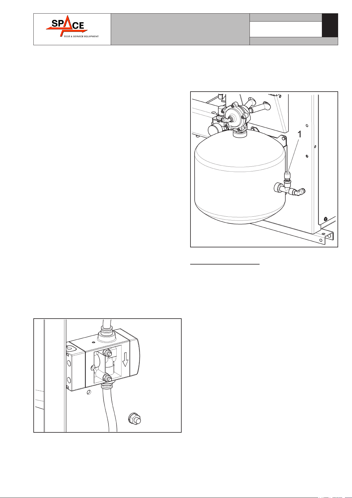
• Safety valve 12bar on tank (valid for version with
pressure regulator - GA2645ID.26).
The safety valve (see the following figure ref. 1)
avoids that the inflation tank is under a pressure
above 12 bar.
3.1 Residual risks
The machine was subjected to a complete analysis of
risks according to reference standard EN ISO 12100.
Risks are as reduced as possible in relation with tech-
nology and product functionality.
This manual stresses possible residual risks, also
highlighted in pictograms on the present manual and
adhesive warning signals placed on the machine: their
location is represented in “PLATE LOCATION ON MA-
CHINE INFORMATION TABLE” on page 5.

INSTRUCTION, USE AND
MAINTENANCE MANUAL
Page 9 of 45
GB
4.0 GENERAL SAFETY RULES
• Any tampering with or modification to the machine
not previously authorized by the manufacturer ex-
empts the latter from all responsibility for damage
caused by or derived from said actions.
• Removing of or tampering with the safety devices or
with the warning signals placed on the machine leads
to serious dangers and represents a transgression of
European safety rules.
• The machine may be used only in areas free from
the danger of explosion or fire.
• The use of only original accessories and spare parts
is advised. Our machine is designed to function only
with original accessories.
• Installation must be conducted only by qualified
personnel exactly according to the instructions that
are given below.
• Ensure that there are no dangerous situations dur-
ing the machine operating manoeuvres. Immediately
stop the machine if it miss-functions and contact the
assistance service of an authorized dealer.
• In emergency situations and before carrying out any
maintenance or repairs, disconnect all supplies to
the machine by using the main switch.
• Ensure that the work area around the machine is free
of potentially dangerous objects and that there is no
oil since this could damage the tyre. Oil on the floor
is also a potential danger for the operator.
THE MANUFACTURER DENIES
ANY RESPONSIBILITY IN CASE
OF DAMAGES CAUSED BY UNAU-
THORIZED MODIFICATIONS OR
BY THE USE OF NON ORIGINAL
COMPONENTS OR EQUIPMENT.
OPERATORS MUST WEAR SUIT-
ABLE WORK CLOTHES, PROTEC-
TIVE GLASSES AND GLOVES,
AGAINST THE DANGER FROM
THE SPRAYING OF DANGEROUS
DUST, AND POSSIBLY LOWER
BACK SUPPORTS FOR THE LIFT-
ING OF HEAVY PARTS. DANGLING
OBJECTS LIKE BRACELETS MUST
NOT BE WORN, AND LONG HAIR
MUST BE TIED UP. FOOTWEAR
SHOULD BE ADEQUATE FOR THE
TYPE OF OPERATIONS TO BE CAR-
RIED OUT.
• The machine handles and operating grips must be
kept clean and free from oil.
• The workshop must be kept clean, dry and not
exposed to atmospheric agents. Make sure that the
working premises are properly lit.
The machine can be operated by a single operator.
Unauthorised personnel must remain outside the
working area, as shown in Figure 4.
Avoid any hazardous situations. Do not use air-
operated or electrical equipment when the shop is
damp or the floor slippery and do not expose such
tools to atmospheric agents.
• During inflation do not lean on the tyre or remain
above it. When beading in the tyre, keep hands away
from tyre and the rim edge.
• During inflation always stay to the side of the machine
and never in front of it.
• When operating and servicing this ma-
chine, carefully follow all applicable safe-
ty and accident-prevention precautions.
The machine must not be operated by professionally
unskilled persons.
IN CASE OF A CHANCE SUPPLY
FAILURE (WHETHER ELECTRIC-
ITY OR COMPRESSED AIR), MOVE
THE PEDALS TO THE NEUTRAL
POSITION.
Space s.r.l.
7300-M009-0_P
GA2645 - GA2645D - GA2645V
INSTRUCTION, USE AND
MAINTENANCE MANUAL Page 10 of 45 GB
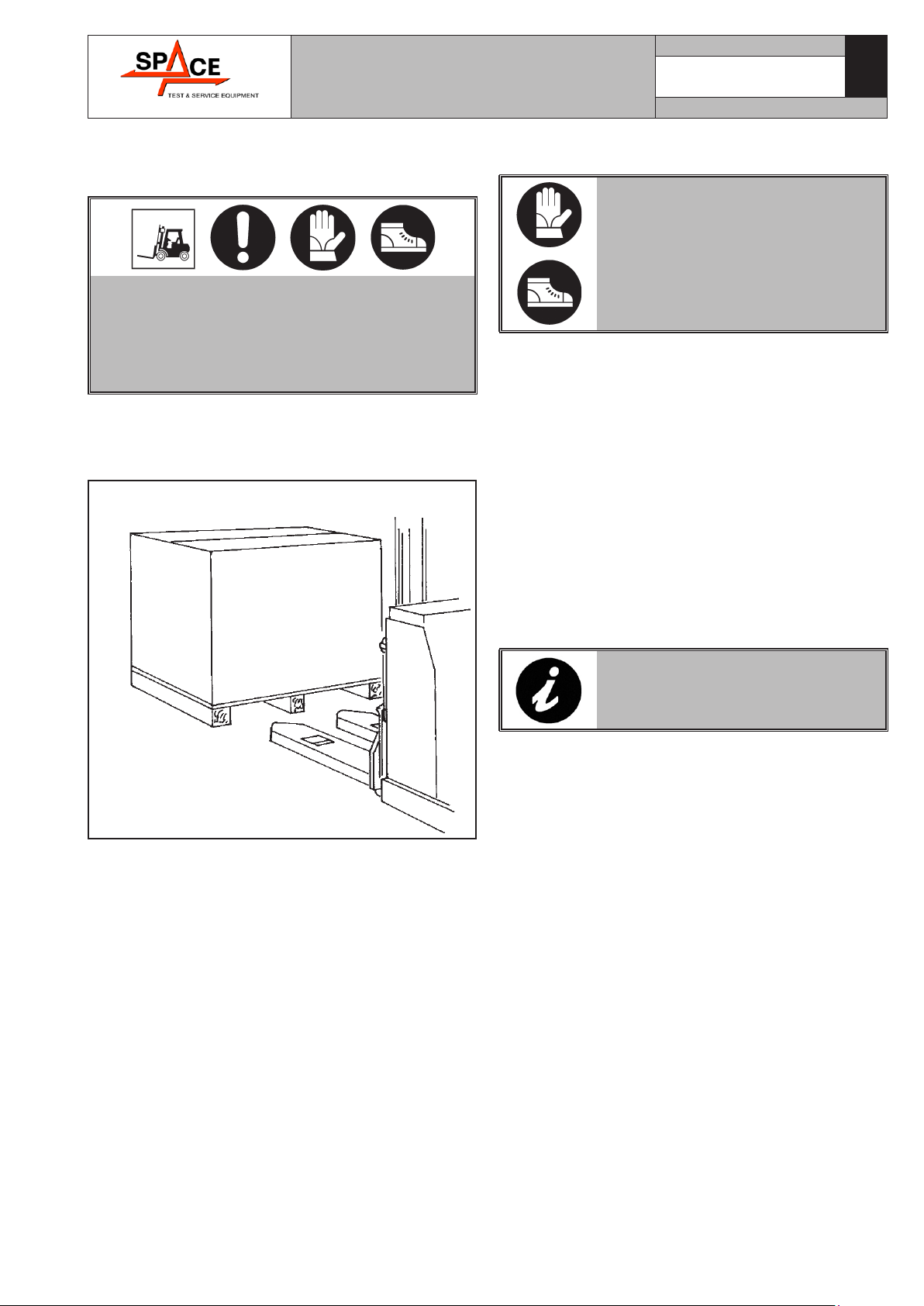
5.0 PACKING AND MOBILIZATION FOR
TRANSPORT
HAVE THE MACHINE HANDLED BY SKILLED
PERSONNEL ONLY.
THE LIFTING EQUIPMENT MUST WITHSTAND
A MINIMUM RATED LOAD EQUAL TO THE
WEIGHT OF THE PACKED MACHINE (see para-
graph “TECHNICAL SPECIFICATIONS”).
The machine is packed in a carton box which size is
mm 1150x1120x1900.
Movement must be by pallet-lift or fork-lift trolley.
The fork lifting points are indicated on the packing.
Fig. 2
6.0 UNPACKING
DURING UNPACKING, ALWAYS
WEAR GLOVES TO PREVENT ANY
INJURY CAUSED BY CONTACT
WITH PACKAGING MATERIAL
(NAILS, ETC.).
The cardboard box is supported with plastic strapping.
Cut the strapping with suitable scissors. Use a small
knife to cut along the lateral axis of the box and open
it like a fan.
It is also possible to unnail the cardboard box from
the pallet it is fixed to. After removing the packing, and
in the case of the machine packed fully assembled,
check that the machine is complete and that there is
no visible damage.
If in doubt do not use the machine and refer to pro-
fessionally qualified personnel (to the seller).
The packing (plastic bags, expanded polystyrene, nails,
screws, timber, etc.) should not be left within reach
of children since it is potentially dangerous. These
materials should be deposited in the relevant collec-
tion points if they are pollutants or non biodegradable.
THE BOX CONTAINING THE FIX-
TURES IS CONTAINED IN THE
WRAPPING. DO NOT THROW IT
AWAY WITH THE PACKING.
Space s.r.l.
7300-M009-0_P
GA2645 - GA2645D - GA2645V

INSTRUCTION, USE AND
MAINTENANCE MANUAL
Page 11 of 45
GB
7.0 MOBILIZATION
THE LIFTING EQUIPMENT MUST WITHSTAND
A MINIMUM RATED LOAD EQUAL TO THE
WEIGHT OF THE MACHINE (SEE PARAGRAPH
TECHNICAL SPECIFICATIONS). DO NOT AL-
LOW THE LIFTED MACHINE TO SWING.
If the machine has to be moved from its normal work
post, the movement must be conducted following the
instructions listed below (see Fig. 3).
• close completely mandrel jaws;
• turn the mandrel until its straight sides are aligned
with machine sides;
• disconnect all machine power supply sources;
• move to limit switch in central position the arm
(Fig. 3 ref. 2);
• remove horizontal arm guard by unscrewing the
provided fixing screws;
• sling the machine using belts with a minimum width
of 60 mm;
• pass the first belt behind the horizontal arm as shown
in the figure;
• pass the second belt between the two front openings
of the self-centring table (Fig. 3 ref. 1);
• pass the third belt between the two rear openings of
the self-centring table (Fig. 3 ref. 1);
• tie up support belt ends above the machine using a
suitable belt ring;
• lift and transport with suitable device with adequate
dimensions.
2
1
Fig. 3
8.0 WORKING ENVIRONMENT CONDI-
TIONS
The machine must be operated under proper condi-
tions as follows:
• temperature: 0° + 55° C
• relative humidity 30 - 95% (dew-free)
• atmospheric pressure: 860 - 1060 hPa (mbar).
The use of the machine in ambient conditions other
than those specified above is only allowed after prior
agreement with and approval of the manufacturer.
8.1 Working position
In Figure 4 it is possible to identify working positions
A and B.
Position A is the main position for wheel fitting and
removal with the mandrel, while position B is ideal to
follow wheel bead breaking operations.
Working in these positions allows better precision and
speed during operating phases as well as greater safety
for the operator.
8.2 Installation space
Fig. 4
USE THE MACHINE IN A DRY AND AD-
EQUATELY LIT PLACE, POSSIBLY INDOORS
OR ANYWAY IN A ROOFED AREA, THIS PLACE
MUST BE IN COMPLIANCE WITH APPLICABLE
SAFETY REGULATIONS.
The location of the machine requires a usable space as
indicated in Figure 4. The positioning of the machine
must be according to the distances shown. From the
control position the operator is able to observe all the
machine and surrounding area. He must prevent unau-
thorized personnel or objects that could be dangerous
from entering the area.
Space s.r.l.
7300-M009-0_P
GA2645 - GA2645D - GA2645V

INSTRUCTION, USE AND
MAINTENANCE MANUAL Page 12 of 45 GB
The machine must be fixed on a flat floor surface,
preferably of cement or tiled. Avoid yielding or irregu-
lar surfaces.
The base floor must be able to support the loads
transmitted during operation. This surface must have
a capacity load of at least 500 kg/m².
The depth of the solid floor must be sufficient to guar-
antee that the anchoring bolts hold.
8.3 Lighting
The machine does not require its own lighting for
normal working operations.
However, it must be placed in an adequately lit envi-
ronment.
For correct lighting, use lamps having total power
800/1200 Watt as envisaged by UNI 10380.
9.0 ANCHORING SYSTEM
The packed machine is fixed to the support pallet
through the holes prearranged on the frame. Such
holes can be used also to fix the machine to the ground,
through floor anchor small blocks (excluded from sup-
ply). Before carrying out the definitive fixing, check that
all the anchor points are laid down flat and correctly
in contact with the fixing surface itself. If not so, insert
shimming profiles between the machine and the fixing
lower surface, as indicated in Fig. 5.
Fig. 5
a= 762
b= 410
c= 525
• Execute 4 holes with 10 mm diameter on the floor
by the holes on the bottom floor;
• insert the small blocks (excluded from supply) into
the holes;
• fix the machine to the ground with 4 M8x80 mm
screws (excluded from supply) (Fig. 5 ref. 1) (or
with 4 8x80 mm stud bolts (excluded from supply)).
Tighten the screws with an approximate tightening
torque of 70 Nm.
10.0 ASSEMBLY AND PREPARATION FOR
USE
After having freed the various components from the
packing check that they are complete, and that there
are no anomalies, then comply with the following in-
structions for the assembly of the components making
use of the attached series of illustrations.
10.1 Assembly procedures
Remove the packaging and free the machine from the
wrapping. Lift the machine and position it on the floor.
10.2 Post assembly
In case the post is supplied demounted, proceed fol-
lowing the instructions below.
1. Remove the fixing elements needed to fix the machine
to the pallet.
2. Unpack the vertical post (Fig. 6 ref. 1) and put it
vertically onto the base.
3. Put the post (Fig. 6 ref. 1) onto the base (Fig. 6
ref. 2) and fit the pin (Fig. 6 ref. 3) into the spe-
cial hole (Fig. 6 ref. 4) and block it through the
washers (Fig. 6 ref. 5), the spacers (Fig. 6 ref. 6)
and the screws (Fig. 6 ref. 7). Fix the post control
cylinder (Fig. 6 ref. 8) using the pin (Fig. 6 ref. 9)
and the seegers (Fig. 6 ref. 10).
1
2
765
3
910
6
7
10
8
4
5
Fig. 6
4. At the end mount the rod covering by means of the
supplied screws and washers.
Space s.r.l.
7300-M009-0_P
GA2645 - GA2645D - GA2645V

INSTRUCTION, USE AND
MAINTENANCE MANUAL
Page 13 of 45
GB
2. Connect the flexible pipes (Fig. 9A-9B ref. 1)
preassembled on the mandrel rotary distribu-
tor (Fig. 9A-9B ref. 2), on the valve (Fig. 9A-9B
ref. 4) hosenipple (Fig. 9A-9B ref. 3). Fasten the
pipes (Fig. 9A-9B ref. 1) with the prepared clamps
(Fig. 9A-9B ref. 5).
3. Connect the pipe (Fig. 9A-9B ref. 14) from the
greaser reduction gear filter (Fig. 9A-9B ref. 7)
(air not lubricated) to the pedalboard (Fig. 9A-9B
ref. 12).
4. Connect the pipe (Fig. 9A-9B ref. 11) from the
pedal board lower valve (Fig. 9A-9B ref. 12) to the
blow valve (Fig. 9A-9B ref. 4) union (Fig. 9A-9B
ref. 13)
5. Connect the pipe (Fig. 9A-9B ref. 6) to the T cou-
pling (Fig. 9A-9B ref. 8) and the coupling (Fig. 9A-
9B ref. 16) placed on the tank (Fig. 9A-9B ref. 9).
6. Connect the pipe (Fig. 9A-9B ref. 10) from the valve
(Fig. 9A ref. 15) or the microregulator (Fig. 9B
ref. 15) to the pedalboard (Fig. 9A-9B ref. 12).
7. Connect the pipe (Fig. 9 ref. 17) from the valve
(Fig. 9A ref. 15) or the microregulator (Fig. 9B
ref. 15) to the inflation unit (Fig. 9 ref. 18).
Fig. 9A
10.3 Bead breaker arm mounting
Secure the beading arm vane (Fig. 7 ref. 1) using the
washers (Fig. 7 ref. 2) and the nut (Fig. 7 ref. 3),
on issue (nut and washers are clamped on the bead
breaker vane).
Fig. 7
10.4 Tubeless inflation mounting (only for
I and IT version)
1. Mount the tank (Fig. 8 ref. 1) on the base rear part,
as shown in Fig. 8, using the screws (Fig. 8 ref. 2)
(tightening torque approx. 8 N·m), the washers
(Fig. 8 ref. 3) and the nuts (Fig. 8 ref. 4).
2
2
1
3
4
3
4
Fig. 8
Space s.r.l.
7300-M009-0_P
GA2645 - GA2645D - GA2645V
INSTRUCTION, USE AND
MAINTENANCE MANUAL Page 14 of 45 GB
10.5 Electrical connections
EVEN THE TINIEST PROCEDURE
OF AN ELECTRICAL NATURE
MUST BE CARRIED OUT BY PRO-
FESSIONALLY QUALIFIED STAFF.
BEFORE CONNECTING THE MA-
CHINE MAKE SURE THAT:
• THE MAIN POWER RATING COR-
RESPONDS TO THE MACHINE
RATING AS SHOWN ON THE
MACHINE PLATE;
• ALL MAIN POWER COMPO-
NENTS ARE IN GOOD CONDI-
TION;
• THE ELECTRICAL SYSTEM
IS PROPERLY GROUNDED
(GROUND WIRE MUST BE THE
SAME CROSS-SECTION AREA
AS THE LARGEST POWER SUP-
PLY CABLES OR GREATER);
• MAKE SURE THAT THE ELEC-
TRICAL SYSTEM FEATURES A
CUTOUT WITH DIFFERENTIAL
PROTECTION SET AT 30 MA.
As envisaged by the regulations in force, the machine is
not equipped with a master circuit breaker, but simply
has a plug-socket connection to the electrical mains.
The machine is supplied with free cable of mt. 3. A plug
corresponding to the following requirements must be
connected to the cable:
• Conformity to Norm IEC 309
• 230/400 Volt – 16A
• 3P + Ground
• IP 44
Only for versions with inverter
• Conformity to Norm IEC 309
• 220/240 Volt – 32A
• 2P + Ground
• IP 44
Space s.r.l.
7300-M009-0_P
GA2645 - GA2645D - GA2645V
Valid for version with pressure regulator -
GA2645ID.26
Fig. 9B
IN CASE OF A CHANCE SUP-
PLY FAILURE, AND/OR BEFORE
ANY PNEUMATIC CONNECTIONS,
MOVE THE CONTROLS TO THE
NEUTRAL POSITION.
INSTRUCTION, USE AND
MAINTENANCE MANUAL
Page 15 of 45
GB
FAILURE TO OBSERVE THE ABOVE
INSTRUCTIONS WILL IMMEDIATE-
LY INVALIDATE THE WARRANTY.
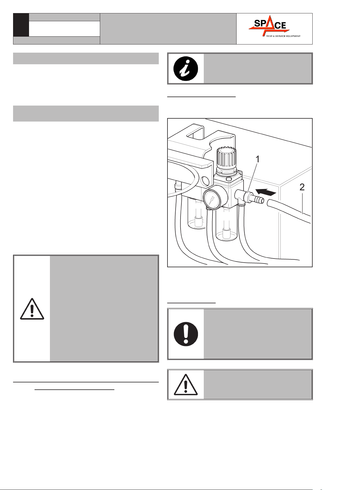
10.7 Air connection
Connect the tyre changer to the workshop compressed
air system by means of plug (Fig. 10 ref. 1).
Fig. 10
The pressurized pipe coming from the mains must
have a section of 1/4x10 (Fig. 10 ref. 2).
The filter unit is already mounted on the machine.
10.8 Controls
BEFORE STARTING UP THE TYRE-
CHANGER, BE SURE TO BECOME
FAMILIAR WITH THE LOCATION
AND OPERATION OF ALL CON-
TROLS AND CHECK THEIR PROP-
ER OPERATION (SEE PAR. “CON-
TROLS”).
CARRY OUT A DAILY CHECK OF
MAINTAINED-TYPE CONTROLS
CORRECT FUNCTIONING, BEFORE
STARTING MACHINE OPERATION.
Space s.r.l.
7300-M009-0_P
GA2645 - GA2645D - GA2645V
Only for 110V - 60Hz monophasic version
• Conformity to Norm IEC 309
• 110V - 60Hz – 32A
• 1P + N + Ground
• Protection degree IP 44 or equivalent
Only for monophasic 110V - 60Hz version with
CSA cable
The machine is supplied with bipolar cable of 2 m,
CSA certified. A plug corresponding to the following
requirements must be connected to the cable:
• Conformity to Norm UL/CSA
• 110V - 60Hz – 32A
• 1P + N + Ground
• Protection degree IP 44 or equivalent
On delivery, the machines are preset to operate at a
voltage of 230/400 V - 50-60 Hz three-phase (for version
GA2645) or at a voltage of 230/400 V - 50 Hz three-
phase (for version GA2645V) and with a monophasic
voltage from 200 to 265 V - 50-60 Hz (for version
GA2645D).
For any other type of power supply, ask the manufac-
turer at the time of purchase: a machine functioning
under the required voltage conditions will be prepared.
FIT A TYPE-APPROVED PLUG
TO THE MACHINE CABLE (THE
GROUND WIRE IS YELLOW/GREEN
AND MUST NEVER BE CONNECT-
ED TO ONE OF THE TWO PHASE
LEADS).
MAKE SURE THAT THE ELECTRI-
CAL SYSTEM IS COMPATIBLE
WITH THE RATED POWER AB-
SORPTION SPECIFIED IN THIS
MANUAL AND APT TO ENSURE
THAT VOLTAGE DROP UNDER
FULL LOAD WILL NOT EXCEED
4% OF RATED VOLTAGE (10%
UPON START-UP).
10.6 Direction of rotation of motor (versions
with three phase motor)
Once all power connections have been made, make
sure that the mandrel is rotating in the right direction
(pedal lowered, clockwise rotation). If the direction of
rotation is wrong, swap two phase wires in the plug.

INSTRUCTION, USE AND
MAINTENANCE MANUAL Page 16 of 45 GB
Fig. 11
11.2 Inflation pedal (on demand)
The pressure on the inflation pedal and the keeping it
pressed, delivers air at controlled pressure (max 4,2
± 0,2 bar).
DO NOT CHANGE THE SET OP-
ERATING PRESSURE VALUE BY
MEANS OF THE MAXIMUM PRES-
SURE VALVES. THE MANUFAC-
TURER SHALL NOT BE RESPON-
SIBLE FOR INJURY OR DAMAGE
ARISING FROM UNAUTHORISED
CHANGES.
11.0 CONTROLS
The pedal control unit comprises 5 (five) pedals.
11.1 5 pedals control unit
“Pedal 1” on this type of pedal control unit activates
the automatic post and has two fixed operative func-
tions:
the first one (with pedal up) overturns the post from
the operator's opposite side; the second one (with pedal
down) brings back the post to working position.
“Pedal 2” opens and closes the locking jaws of the
self-centering device. It has three stable positions:
open – close – approach jaws.
“Pedal 3” controls turntable rotation and has 3 stable
positions:
1. 0 position, turntable stopped;
2. Pressed down, the turntable is rotated clockwise;
3. Raised, the turntable is rotated anti-clockwise.
ONLY FOR VERSIONS WITH THREE-
PHASE 230/400 V - 50 HZ 2 SPEED
“Pedal 3” controls turntable rotation and has 4 stable
positions:
1. 0 position, turntable stopped;
2. Position 1 downwards - clockwise rotation of turn-
table;
3. Position 2 downwards from position 1 - clockwise
rotation of turntable at double speed;
4. Position 1 upwards - counterclockwise rotation of
turntable;
“Pedal 4” has 2 operative positions: when it is pressed
downwards, the cylinder for bead breaking with lateral
arm (A) is operated; when such pedal is released, the
bead breaking arm is moved back to the initial position
(open bead breaker) (B).
The inflation “pedal 5” (only for “I” and “IT” versions)
has three positions:
1. completely lowered “unstable”: to cause air (con-
tained in the reservoir) to be jetted out through air
lances;
2. middle stroke “unstable” position: it lets air out
from inflating head;
3. released “stable” position: it closes air outlets.
DO NOT CHANGE THE SET OP-
ERATING PRESSURE VALUE BY
MEANS OF THE MAXIMUM PRES-
SURE VALVES. THE MANUFAC-
TURER SHALL NOT BE RESPON-
SIBLE FOR INJURY OR DAMAGE
ARISING FROM UNAUTHORISED
CHANGES.
Space s.r.l.
7300-M009-0_P
GA2645 - GA2645D - GA2645V
INSTRUCTION, USE AND
MAINTENANCE MANUAL
Page 17 of 45
GB
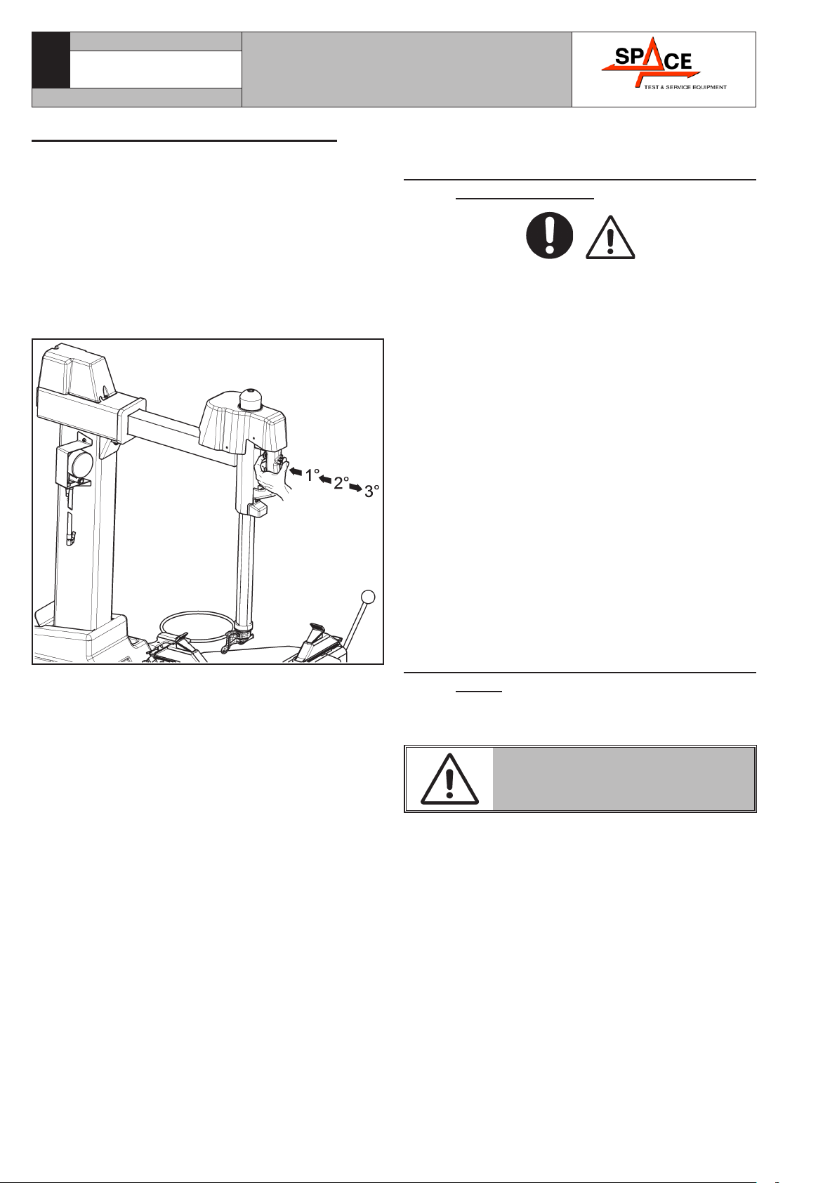
11.3 Post handle manual adjustment
On the post is placed a pneumatically controlled handle
that allows the locking and unlocking of the vertical
and horizontal arm.
Pushing the push-button located on this handle
(Fig. 12) the following operations can be carried out:
1st tripping: locking of the vertical and horizontal arm
in working position;
2nd tripping: unlocking of vertical and horizontal arm
and manual rise of vertical arm in rest position (all
upward).
Fig. 12
12.0 USING THE MACHINE
12.1 Precaution measures during tyre re-
moval and fitting
Before fitting a tyre, observe the following safety rules:
• rim and tyre must be clean, dry and in good condi-
tion; if necessary, remove the balancing weights and
clean the rim. Check that:
- neither the bead nor the tread of the tyre are dam-
aged;
- the rim does not produce dents and/or deformation
(especially for alloy rims, dents can cause internal
micro-fractures, that pass unobserved at visual
inspection, and can compromise the solidity of the
rim and constitute danger even during inflation);
• adequately lubricate the contact surface of rim and
tyre bead, using specific tyre lubricants only;
• replace the inner tube valve with a new valve, if the
tyre tube has a metal valve, replace the grommet;
• make sure that the tyre is the right size for the rim;
on the contrary, never fit a tyre unless you are sure
it is the right size (the rated size of the rim and tyre
is usually printed directly on each of them);
• do not use compressed air or water jets to clean the
wheels on the machine.
12.2 Preliminary operations - Preparing the
wheel
• Remove the wheel balancing weights from both sides
of the wheel.
REMOVE THE VALVE STEM AND
ALLOW THE TYRE TO COMPLETE-
LY DEFLATE.
• Establish from which side the tyre should be de-
mounted, checking the position of the groove.
• Find the rim locking type.
• Try to establish the special types of wheels, such as
“TD” and “AH”, in order to improve locking, bead
breaking, assembly and disassembly performances.
Space s.r.l.
7300-M009-0_P
GA2645 - GA2645D - GA2645V
INSTRUCTION, USE AND
MAINTENANCE MANUAL Page 18 of 45 GB
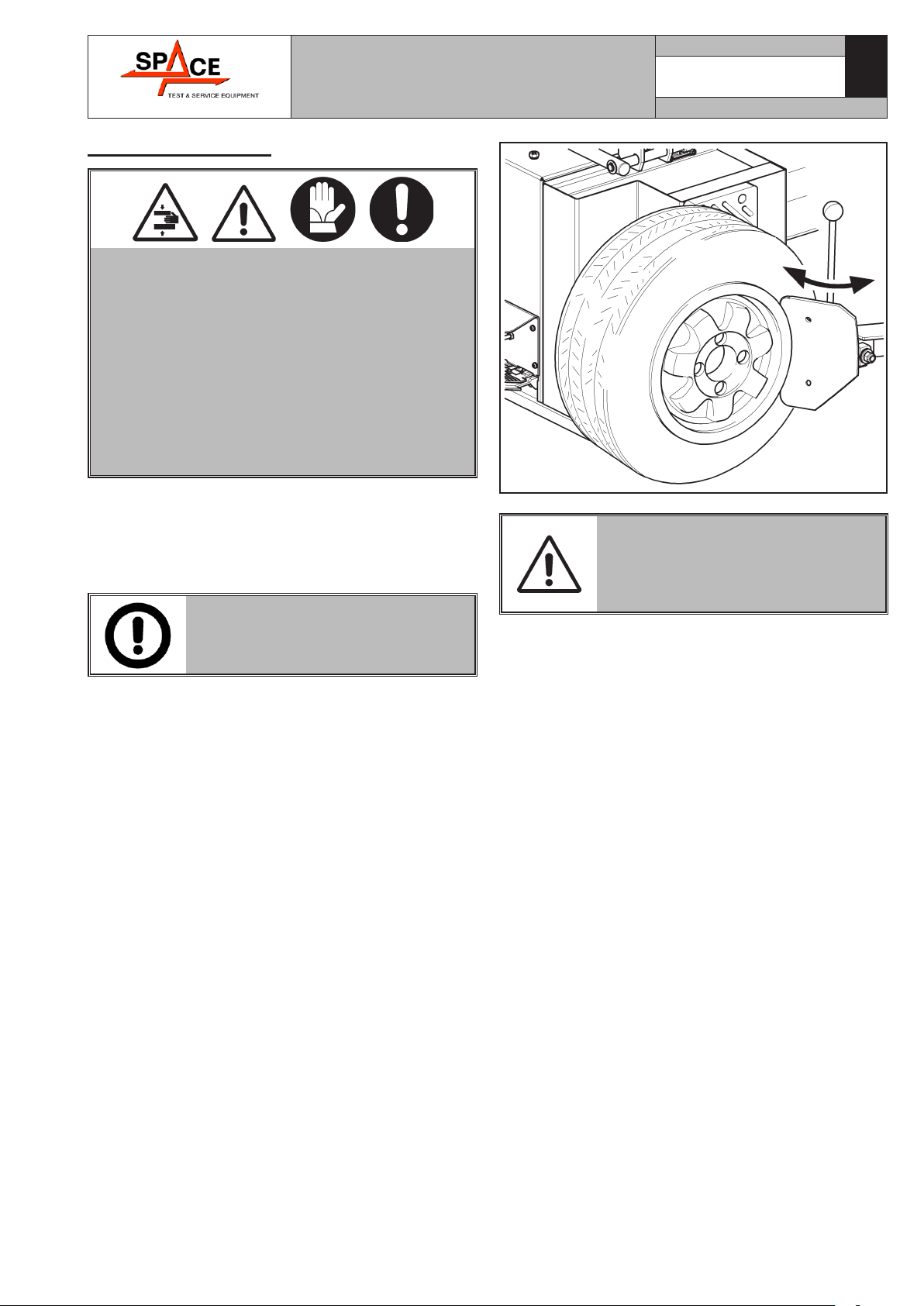
12.3 Bead breaking
TYRE BEADING MUST BE CARRIED OUT AF-
TER THE TYRE HAS BEEN COMPLETELY DE-
FLATED AND OBSERVING ALL SAFETY RULES:
BEADING PEDAL START-UP CAUSE SUDDEN,
STRONG ARM CLAMPING, THUS REPRESENT-
ING POTENTIAL CRUSHING DANGER FOR
ANYTHING WITHIN THE OPERATING AREA.
DURING TYRE BEADING DO NOT LEAN HANDS
ON TYRE SIDES. DURING TYRE BEADING
SUDDEN NOISE LEVEL PEAKS CAN OCCUR:
THEREFORE THE USE OF SAFETY EARCAPS
IS RECOMMENDED.
After preparing the wheel as described in the previous
point, follow the instructions given below to carry out
the bead breaking procedure:
1. Position the wheel as indicated in Fig. 13 and move
the bead breaker tool toward the edge of the rim.
PLACE THE VANE SO THAT IT CAN
OPERATE ON TYRE SIDE AND NOT
ON THE RIM.
2. Operate the bead breaker vane by pressing the rela-
tive pedal until the bead has detached. If the bead
does not detach the first time, repeat the operation,
on different points of the wheel, until it has come
away completely.
3. Reverse the position of the wheel and repeat the
operation on the other side.
4. Lubricate the tyre carefully along the entire cir-
cumference of the bead on both sides. Failure to
lubricate might cause friction between the mounting
tool and the tyre, and would cause damage to the
tyre and/or the bead.
Fig. 13
NEVER INSERT ANY PART OF
YOUR BODY BETWEEN THE BEAD
BREAKER TOOL AND THE TYRE,
OR BETWEEN THE TYRE AND THE
WHEEL SUPPORT.
Space s.r.l.
7300-M009-0_P
GA2645 - GA2645D - GA2645V
INSTRUCTION, USE AND
MAINTENANCE MANUAL
Page 19 of 45
GB
12.4 Wheel clamping on the mandrel
To block the wheel from inside:
1. Grease tyre edges with the grease contained in the
appropriate cup (see operating figure Fig. 14).
2. Release the hexagon shaft (Fig. 14 ref. 2) through
the relevant push-button on handle (Fig. 14 ref. 1)
and take it up, fully home. Control horizontal arm
(Fig. 14 ref. 3) tilting through the pedal.
3. The wheel can be secured to the mandrel by placing
jaws either inside or outside the rim (see Chapter
15 “Technical specifications” for required rim size).
WHEN SECURING THE WHEEL DO
NOT KEEP HANDS UNDER THE
TYRE.
Make sure that the wheel is placed at the centre of
the self-centring table (Fig. 14 ref. 6). Make sure
the wheel is clamped by jaws (Fig. 14 ref. 7) sim-
metrically.
A) WHEEL SECURING (OUTSIDE THE RIM) (for
allowed rim size see Chapter 15. “Technical speci-
fications”)
In order to carry out the clamping of the wheel from
the outside:
1. place the 4 self-centering jaws by using the appro-
priate sub base (Fig. 14 ref. 8) n correspondence
to the required clamping range.
2 pressing pedal (Fig. 14 ref. 9) in intermediate po-
sition, place the 4 fixing jaws (Fig. 14 ref. 7), so
that the reference notch on the mandrel is at about
the same level of the tyre diameter notched on the
sliding element.
3. Place the wheel on the mandrel, press the rim down-
ward and completely lower pedal (Fig. 14 ref. 9)
to secure the wheel.
B) WHEEL SECURING (INSIDE THE RIM) (for al-
lowed rim size, see Chapter 15. “Technical speci-
fications”)
To block the wheel from inside:
1. place the 4 self-centering jaws by using the appro-
priate sub base (Fig. 14 ref. 8) n correspondence
to the required clamping range.
2. close preventively fixing jaws (Fig. 14 ref. 7), by
means of pedal (Fig. 14 ref. 9). Place the wheel on
the mandrel. Push down the rim while completing
lowering the pedal and releasing it. The jaws release,
thus securing the rim.
Fig. 14
Space s.r.l.
7300-M009-0_P
GA2645 - GA2645D - GA2645V
INSTRUCTION, USE AND
MAINTENANCE MANUAL Page 20 of 45 GB
12.5 Demounting
KEEP YOUR HANDS AND BODY
AWAY FROM MOUNTING TOOL
DURING DISASSEMBLY/ASSEM-
BLY OPERATIONS TO AVOID
SQUASHING DANGER.
After clamping the wheel, the tyre is demounted fol-
lowing the instructions given below, with reference to
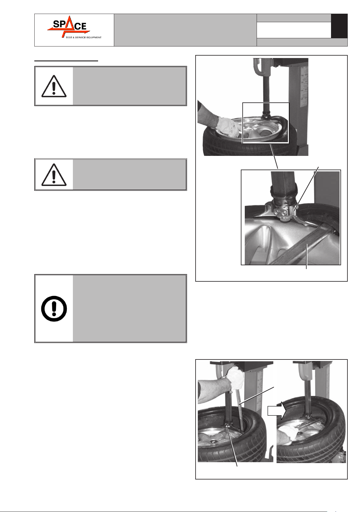
Fig. 15.
1. Press the rotation pedal to rotate the wheel clockwise
until the valve stem reaches “ hour 1” position.
2. Place arm (Fig. 14 ref. 3) in working position.
WHEN PLACING ARM IN WORKING
POSITION, DO NOT LEAN HANDS
ON THE RIM: DANGER OF SQEEZ-
ING BETWEEN HEAD AND RIM.
3. Release the hexagon shaft (Fig. 14 ref. 2) and set
tool (Fig. 14 ref. 5) radially and vertically on rim
and lock it in place using the push-button on handle
(Fig. 14 ref. 1);
4. operate lever (Fig. 15 ref. 1) to place tyre bead on
the head nail (Fig. 15 ref. 2).
5. While keeping the lever in this position, turn the
mandrel clockwise by means of pedal (Fig. 14
ref. 10), until the bead is out of the rim. Operate
the pedal by quickly pressing and releasing it.
WHEN OPERATING ON VERY
“HARD” RIMS, THE TYRE BEAD
TENDS TO SLIP DOWN THE HEAD.
BEFORE TURNING THE MAN-
DREL CLOCKWISE, TURN IT AN-
TICLOCKWISE BY A FEW CENTIM-
ETERS WHILE KEEPING LEVER
(Fig. 15 ref. 1) IN THE SAME
POSITION.
2
1
Fig. 15
6 remove the inner tube (if fitted);
7 place the head as indicated at point 3; then by means
of lever (Fig. 16 ref. 1) place the other tyre bead
on the head nail (Fig. 16 ref. 2);
8. while keeping the lever (Fig. 16 ref. 1) in this posi-
tion, turn the mandrel clockwise until the bead is
out of the rim.
9. place the arm in idle position and remove the tyre
from the rim.
1
2Fig. 16
Space s.r.l.
7300-M009-0_P
GA2645 - GA2645D - GA2645V
This manual suits for next models
35
Table of contents
Popular Tyre Changer manuals by other brands


Hunter
Hunter TCA34R Series Operation instructions

Ranger Products
Ranger Products R30XLT Installation and operation manual

Hofmann Megaplan
Hofmann Megaplan Megamount Twister EVO CP Installation, operation and maintenance guide

Butler
Butler SEIDO.30 instruction manual

Cormach
Cormach PUMA Use and maintenance manual

Fasep
Fasep V585.2.U user manual

Fasep
Fasep RAE.2108 instruction manual

GIULIANO
GIULIANO S 554 Use and maintenance instructions

Ranger
Ranger R745 Installation and operation manual

Black Diamond Equipment
Black Diamond Equipment TC1024DCA instructions

TSI Instruments
TSI Instruments CH-22 manual

Mondolfo Ferro
Mondolfo Ferro TBE160 MATIC Operator's manual