SPALDING NBA Arena User manual

106/12 ID# M7409124
)>;;A44DBC><4A(4AE824#D<14A5>A*(>A0=030
>ADA>?4(F434=>ADBCA0;80
=C4A=4C33A4BBFFFB?0;38=62><FFFB?0;38=62><0D
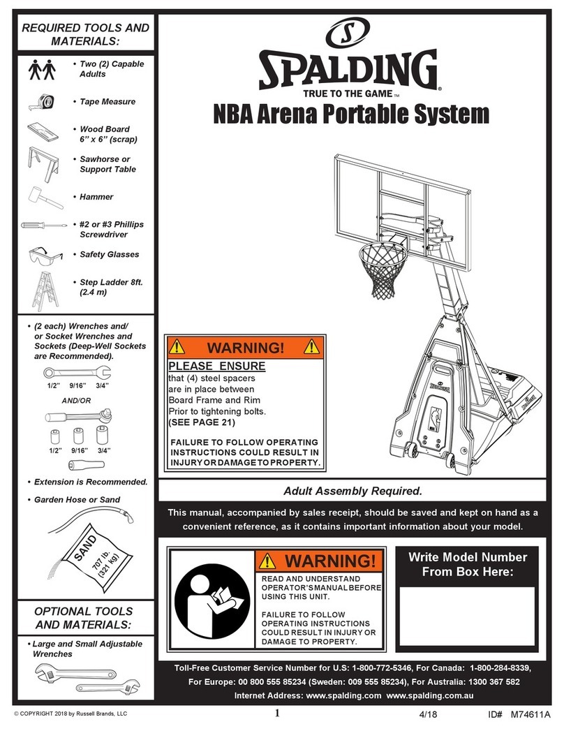
RE UIRED TOOLS AND
MATERIALS:
OPTIONAL TOOLS
AND MATERIALS:
(?0;38=6
'#*#'()#
$%')$'("#*!$'
*(#)(*#)
!*')$$!!$,
$%')##()'*)$#(
$*!'(*!)##*'.$'
")$%'$%').
,'##
• Two (2) Capable
Adults
• Tape Measure
• Wood Board
6” x 6” (scrap)
• Sawhorse or
Support Table
• Hammer
• #2 or #3 Phillips
Screwdriver
• Safety Glasses
• Step Ladder 8ft.
(2.4 m)
(#
(#
;1
;1
:6
:6
,A8C4">34;#D<14A
A><>G4A4
• (2 each) Wrenches and/or
Socket Wrenches and
Sockets (Deep-Well Sockets
are Recommended).
• Extension is Recommended.
• Garden Hose or Sand
• Large and Small Adjustable
Wrenches
© COPYRIGHT 2012 by SPA DING
AND/OR
)78B<0=D0;022><?0=8431HB0;4BA4248?CB7>D;314B0E430=3:4?C>=70=30B0
2>=E4=84=CA454A4=240B8C2>=C08=B8<?>AC0=C8=5>A<0C8>=01>DCH>DA<>34;
Adult Assembly Required.
NBA Arena Portable System

2
574090 12/06
MOVING SYSTEM
HEIGHT
ADJUSTMENT
B
A
Rotate crank
handle to raise
and lower
backboard.
Do not over crank
handle beyond the
manufactured height
indicator range of
7-1/2 - 10 feet.
Damage may be
caused to the screw
jack’s internal
adjustment
mechanism if
adjusted over 10 or
under 7-1/2 feet.
1
32
4
1.
2.
3.
4.
5.
Adjust basketball backboard height to
lowest postion.
Rotate handle forward until wheels
engage ground.
Move basketball system to desired location.
Rotate handle back to original position.
Check system for stability.
53
Owner must ensure that all players know and follow these rules
for safe operation of the system.
WARNING
•
DO NOT HANG on the rim or any part of the system including
backboard, support braces or net.
•
During play, especially when performing dunk type activities,
keep player's face away from the backboard, rim and net.
Serious injury could occur if teeth/face come in contact with
backboard, rim or net.
•
Do not slide, climb, shake or play on base and/or pole.
•
After assembly is complete, fill system completely with water
or sand and stake to the ground. Never leave system in an
upright position without filling base with weight, as system
may tip over causing injuries.
•
When adjusting height or moving system, keep hands and
fingers away from moving parts.
•
Do not allow children to move or adjust system.
•
During play, do not wear jewelry (rings, watches, necklaces,
etc.). Objects may entangle in net.
•
Surface beneath the base must be smooth and free of gravel or
other sharp objects. Punctures cause leakage and could cause
system to tip over.
•
Keep organic material away from pole base. Grass, litter, etc.
could cause corrosion and/or deterioration.
•
Check pole system for signs of corrosion (rust, pitting, chipping)
and repaint with exterior enamel paint. If rust has penetrated
through the steel anywhere, replace pole immediately.
•
Check system before each use for proper ballast, loose
hardware, excessive wear and signs corrosion and repair
before use.
•
Check system before each use for instability.
•
Do not use system during windy and/or severe weather
conditions; system may tip over. Place system in the storage
position and/or in an area protected from the wind and free
from personal property and/or overhead wires.
•
Never play on damaged equipment.
•
See instruction manual for proper installation and
maintenance.
•
When moving system, use caution to keep mechanism from
shifting.
•
Keep pole top covered with cap at all times.
•
Do not allow water in tank to freeze. During sub-freezing
weather add 2 gallons of non-toxic antifreeze, sand or empty
tank completely and store. (Do not use salt.)
•
While moving system, do not allow anyone to stand or sit on
base or have added ballasting on base.
•
Do not leave system unsupervised or play on system when
wheels are engaged for moving.
•
Use Caution when moving system across uneven surfaces.
System may tip over.
•
Use extreme caution if placing system on sloped surface.
System may tip over more easily.
Read and understand warnings listed below
before using this product.
Failure to follow these warnings may result in
serious injury and/or property damage.
ID#: 55679001 02/12
In the U.S.: 1-800-558-5234 In the U.S.: 1-800-558-5234
In Canada: 1-800-284-8339
In the U.S.: 1-800-334-9111
In the U.S.: 1-800-558-5234
In Canada: 1-800-284-8339
In Au s t r a lia: 1-3 0 0 - 3 67-582
Trademarks registered
in the USA and other countries.

3
$'T.$*T()')
To ensure optimal playability of backboard system, a close tolerance
fit between the elevator components and hardware is required. Test-fit
large bolts into large holes of elevator tubes, backboard brackets, and
triangle plates. Carefully rock them in a circular motion to ream out
any excess paint from holes if necessary.
Not all items pictured are included with every model.
().#()'*)$#(
!*')$$!!$,)(().#()'*)$#(".'(*!)#('$*(#*'.$'
%'$%')."#,!!+$,''#).
Owner must ensure that all players know and follow these rules for safe operation of the system.
)> 4=BDA4 B054CH 3> =>C 0CC4<?C C> 0BB4<1;4 C78B BHBC4< F8C7>DC 5>;;>F8=6 C74 8=BCAD2C8>=B
20A45D;;H742:4=C8A41>G0=38=B8340;;?02:8=6<0C4A80;5>A?0ACB0=3>A0338C8>=0;8=BCAD2C8>=
<0C4A80;45>A41468==8=60BB4<1;HA403C748=BCAD2C8>=B0=3834=C85H?0ACBDB8=6C7470A3F0A4
834=C8584A0=3?0ACB;8BC8=C78B3>2D<4=C %A>?4A0=32><?;4C40BB4<1;HDB40=3BD?4AE8B8>=0A4
4BB4=C80;5>A?A>?4A>?4A0C8>=0=3C>A43D24C74A8B:>5022834=C>A8=9DAH7867?A>1018;8CH>5
B4A8>DB8=9DAH4G8BCB85C78BBHBC4<8B=>C8=BC0;;43<08=C08=430=3>?4A0C43?A>?4A;H
Most injuries are caused by misuse and/or not following instructions. Use caution when using this system.
M 5DB8=60;0334A3DA8=60BB4<1;HDB44GCA4<420DC8>=
M )F>20?01;403D;CB0A4A42><<4=3435>AC78B>?4A0C8>=
M 742:10B4A46D;0A;H5>A;40:064(;>F;40:B2>D;320DB4BHBC4<C>C8?>E4AD=4G?42C43;H
M (40CC74?>;4B42C8>=B?A>?4A;H850??;8201;408;DA4C>3>B>2>D;30;;>FC74?>;4B42C8>=BC>
B4?0A0C43DA8=6?;0H0=3>ACA0=B?>AC>5C74BHBC4<
M ;8<0C42>AA>B8>=>A<8BDB42>D;3A4BD;C8=BHBC4<508;DA4
M "8=8<D<>?4A0C8>=0;74867C8B<C>C741>CC><>5102:1>0A3
M )78B4@D8?<4=C8B8=C4=3435>A7><4A42A40C8>=0;DB4>=;H0=3#$)4G24BB8E42><?4C8C8E4?;0H
M '4030=3D=34ABC0=3C74F0A=8=6;014;0558G43C>?>;4
M )74;854>5H>DA10B:4C10;;?>;434?4=3B>=<0=H2>=38C8>=B)742;8<0C4?;024<4=C>5C74?>;4
;>20C8>=>5C74?>;44G?>BDA4C>2>AA>B8E4BBD270B?4BC82834B74A182834B>AB0;CB0A40;;
8<?>AC0=C
M
5C427=820;0BB8BC0=248BA4@D8A432>=C02CDBC><4A(4AE824
M 3D;CBD?4AE8B8>=8BA42><<4=343F74=039DBC8=674867C

4
203299(4pcs) 205593(2pcs)
208342 (3pcs)
206665 (4pcs)
206340 (7pcs)
203474 (14pcs)
201651 (4pcs)
AR00002
208251 (4pcs)
#).',''(
()$%$!',''
'$#),!(("!.
',''
!+)$')$%$!
$##)$#',''
!+)$''"(
',''
!
'
'"))"#)
',''#
()*"#$'%
',''
To make the assembly easier we have separated the hardware per section.
Each hardware card is dedicated to a specific assembly area.
Open each individually as you progress through the steps. Do not open them all at once.

5
"%$')#)
'4<>E40;;2>=C4=CB5A><1>G4B
4BDA4C>2742:8=B834?>;4B42C8>=B
70A3F0A40=30338C8>=0;?0ACB0A4?02:438=B834
,'##
.$*'(.()"(&*%%,)#'.! $'-"# $'$'#.
"))".+$*''*'#(%"#)' (#) $'$*!'(*!)
#(*#' $'("##.,.%'$')$$')'(("!.
!!)$!!'#*"'*(#7CC?FFFB?0;38=62><
NOTICE TO ASSEMBLERS
Adult Assembly Required. Dispose of ALL packaging materials promptly. As with all products,
periodically inspect for loose small parts.
Assembled unit MUST be filled with sand or water at ALL times.
ALL basketball systems, including those used for DISPLAYS, MUST be assembled and installed
according to instructions. Failure to follow instructions could result in SERIOUS INJURY. It is NOT
acceptable to devise a makeshift support system.

6
'$#)+, +,
Get to know the basic parts of your basketball system...
BACKBOARD
RIM
TOP PO E
E EVATOR
ASSEMB Y
STADIUM PAD
TOP
STADIUM PAD
BOTTOM
BOTTOM PO E
STRUTS
TOP BASE
BOTTOM
BASE
WHEE
CARRIAGE
ASSEMB Y
GROUND
RESTRAINT
ROPE

7
()$# BASE AND POLE ASSEMBLY
#B8 (1)
#B3 (2)
#B2 (12)
#B7 (4)
#B4 (2) #B5 (4) #B6 (1)
Item ty. Part No. Description
11600076 Top Base
21FR908622 Bottom Pole Section
31FR908661 Top Pole Section
42908459 Strut, Front, 62.75” ong, with Holes
52908699 Strut, Rear, 62.75” ong
B1 4 265523 Bolt, Hex Head, 3/8-16 x 1” ong
B2 12 203309 Washer, Flat, 3/8 x 1 O.D.
Item ty. Part No. Description
B3 2 203041 Nut, Hex-Flange, 3/8-16
B4 2 203331 Bolt, Hex Head, 3/8-16 x 1.5” ong
B5 4 205593 ock-nut, Nylon Insert, 3/8-16
B6 1 206340 ock-nut, Nylon Insert, 1/2-13
B7 4 202602 ock-washer, 0.375 I.D. x 0.675 O.D.
B8 1 206304 Bolt, Hex Head, 1/2-13 x 6-5/16” ong
HARDWARE LIST AND IDENTIFIER
#B1 (4)
()$T%$!',''
,A4=274B
#$'
(>2:4C,A4=274B0=3(>2:4CB
)$$!('&*'$')(()$#
O O GC4=B8>=
O O

8
202900
202900
203041
207585
207692
203309
203331
208253
203309
600200 908624
600074
206340
%'(("!
$"%$##)(
203331
208253
203309
600200
,'##
The components in steps 1 - 3
are factory pre-assembled.
)%'(("!
'($'))#((
If any parts are missing or
damaged please contact our
customer service department to
receive replacement parts (see
page 1 for customer service
information).

9
B4
B2 B2
B4
B3
ASSEMBLY RE UIRED
265523
265523
208253 208253
203309 203309
600075
203309
203309
203309
203309
1
Attach top base (1) to bottom base using bolts (B4),
washers (B2) and nuts (B3).
B2
B2

*)$#
WHEN PROPER Y ASSEMB ED,
THE PO E SECTIONS SHOU D
HAVE A 4" "#"*" OVER AP.
ASSEMB E TOP PO E TO INE
MARKED 4” FROM TOP OF
BOTTOM PO E
10
,>>3(2A0?OGO<8=8<D<
#$)T(*%%!
2
3
)$% $))$"
32
Correctly identify each pole section (TOP and BOTTOM). (!!*()')$#!$,
#$)%;40B438BA460A3?>;4834=C85820C8>=;014;B
"%$')#)
Use pencil or tape and mark a line 4” from top of bottom pole. (("!)$%%$!)$)("'
!# While maintaining alignment, bounce bottom pole section (2) into top section (3) using a wood scrap
as shown until the top pole has a 4” "#"*"overlap of the bottom pole. See *)$# diagram below.
#$)$'#))$#
$%$!()$#
%>B8C8>=4027?>;4B42C8>=B>C70CC74
'$#)T0=3''5024B<0C27C74
8;;DBCA0C8>=F74=0BB4<1;43
()!+,(!$,
,'##
),$%!*!)('&*'
$')(%'$*'!*')$
$!!$,)(,'##$*!
'(*!)#('$*(#*'.
#$'%'$%')."
Bottom
Top
Bottom
Top
2
4"
3
''
$))$"
%$!
''
)$%
%$!
'$#)T
)$% %$!T()$#
'$#)T
$))$" %$!()$#
''
)$%
%$!
''
$))$"
%$!
#$)
' )
!$)$#
#$)
$!
!$)$#
"'
!#
4" (10 cm)

11
,'##
),$%!*!)('&*'
$')(%'$*'!*')$
$!!$,)(,'##$*!
'(*!)#('$*(#*'.
#$'%'$%')."
The flange of the bottom
pole will rest on the nut and
washer of frame plate.
#$)
DC0F0H+84FB
BB4<1;4?>;4C>10B40BB7>F=
Place 4 washers (B2) onto the 4 pre-installed bolts so
they rest on the nuts.
Rest pole on the 4 washers (B2).
Allow 4 pre-attached bolts to pass through the 4 holes in
bottom pole flange.
Secure pole assembly to plate with washers (B2) and nuts (B5)
as shown.
B2
B2
B2
B5
2
B2
B5

12
B6
45
4
5
B8
2
Attach struts (4 and 5) to base frame using
bolts (B1) and lock washers (B7).
Attach struts (4 and 5) to bottom pole (2)
using bolt (B8) and nut (B6).
"%$')#)
#$)$'#))$#$
()'*)(
%82CDA4B7>F=8B0B85
H>D0A45028=6C745A>=C
>5C74BHBC4<
A>=CBCADCB70E4
7>;4B8=C74<C>0CC027
C74BC038D<?03)74
A40ABCADCB$#$)
70E4C747>;4B
,'##
),$%!*!)('&*'
$')(%'$*'!*')$
$!!$,)(,'##$*!
'(*!)#('$*(#*'.
#$'%'$%')."
B1
B7
4
4
4
4
5
5
5
5
DO NOT fully tighten
at this time.
#$)
D;;HC867C4= all
hardware in step 8
and 9 at this time.
#$)
"%$')#)
#$)%$()$#$()'*)(
A>=CBCADCBF8C77>;4B
64C?;02432;>B4BCC>C74?>;4
B1
B7

13
Item ty. Part No. Description
10 2 600074 Wheel, 6”
11 1 600079 Transport Handle, Plastic
12 1 800373 U-Bracket, Pivot
13 1 908466 Bracket, Wheel
14 1 206948 Bracket, Pivot, ower
15 1 206956 Disk, Pivot, Plastic
16 1 908513 Cross Member
17 1 206082 Axle, Rod, 20.5” ong
18 2 908460 Tube, Hinged
W1 2 200514 Bolt, Hex Head, 3/8-16 x 3” ong
Item ty. Part No. Description
W2 12 203041 Nut, Hex-Flange, 3/8-16
W3 4 203299 Washer, 3/8 Flat
W4 2 265563 Bolt, Hex Head, 3/8-16 x 2.5” ong
W5 1 203330 Bolt, Hex Head, 3/8-16 x 4.5” ong
W6 2 205593 ock-Nut, 3/8-16
W7 1 206252 Bolt, Hex Head, 3/8-16 x 1” ong
W8 8 203277 Bolt, Carriage, 3/8-16 x 2”
W9 2 207550 Push Caps, Metal, Wheel Assembly
W10 1 202274 Spacer, 0.379 I.D. x 0.50 O.D. x 3.5” ong
#W1 (2)
#W7 (1)
#W10 (1)
#W4 (2)
#W9 (2)
2
#W8 (8)
#W5 (1)
#W2 (12) #W6 (2)
#W3 (4)
)$$!('&*'$')(()$#
()$# WHEEL CARRIAGE ASSEMBLY
O
O
,A4=274B
#$'
(>2:4C,A4=274B0=3(>2:4CB
GC4=B8>=
HARDWARE LIST AND IDENTIFIER
203299(4pcs) 205593(2pcs)
'$#),!(("!.',''

14
W1
W1
W2
W2
W2
W4
W2
W3
W4
W3
W3
12
4
W3
4
16
Attach u-bracket (12) to cross member (16) using bolts (W4), washers (W3) and nuts (W2).
Secure cross member (16) to front struts (4) using bolts (W1), washer (W3) and nuts (W2)
"%$')#)
#$)$'#))$#
$' )
"%$')#)
#$)$'#))$#
$()'*)'
16
12
"%$')#)
#$)$'#))$#
$()'*)'
$"%!)(("!.

15
18
W8
18
W2 W2
W2
W2
W8
13
)$#()!!($#
%*(#*)
M BB4<1;4%DB7=DC
,744;BG;4=3
,744;A02:4CB
(7>F=
M (D??>AC
%DB7=DCG;4A><
)74=3,8C7;>2:
$5,>>3)>=BC0;;
)74(42>=3%DB7=DC
$=C>)74G;4
#$)
Wood Block
10
10
13
17
W9
W9
Insert axle (17) through wheel bracket (13). Secure wheels (10) to axle using pushnuts (W9). Carefully
tap pushnuts (W9) onto axle with hammer or mallet.
Secure hinge tubes (18) to wheel bracket (13) using bolts (W8), and nuts (W2).
W8
"%$')#)
#$)$'#))$#$
#)*(
)($')#$)
#)*($
*#'),!
' )
18
10

16
W8
W2
W2
16
11
Attach transport handle (11) to wheel
assembly using carriage bolts (W8)
and nuts (W2).
Secure lower pivot bracket (14) to
wheel assembly using bolt (W7),
pivot disk (15) and nut (W6).
Secure wheel assembly to u-
bracket (12) using bolt (W5),
spacer (W10), and nut (W6).
"%$')#)
$#$)$+'))#
$!),
W6
12
W10
15
14
W6
W7
W5

17
Item ty. Part No. Description
20 1 700009 Handle, Screw-Jack
21 1 800972 Screw Jack
22 1 600199 Sleeve, Screw Jack
23 1 600165 Cap, Screw Jack
Item ty. Part No. Description
24 1 202528 Pin, Handle
E1 1 201518 Bolt, Hex-Head, 5/16-18 x 2.75” ong
E2 1 203099 ock-Nut, Nylon Insert, 5/16-18
#E2 (1)
#E1 (1)
HARDWARE LIST AND IDENTIFIER
!
)$$!('&*'$')(()$#
0<<4A>A"0;;4C
!+)$')$%$!$##)$#',''
O
O
,A4=274B
#$'
(>2:4C,A4=274B0=3(>2:4CB
GC4=B8>=
()$# ELEVATOR ASSEMBLY PART 1

18
E2
E1
22
21
23
24
20
Securely rest the assembly on sawhorse.
Slide screw-jack sleeve (22) over screw jack and attach cap (23) to top end.
Attach screw-jack (21, 22, 23) to pole bracket with bolt (E1) and nut (E2) as shown.
Attach handle (20) to screw jack with pin (24).

19
Item ty. Part No. Description
30 1 908508 Elevator Tube, Upper
31 1 908509 Elevator Tube, ower
32 1 Backboard
33 2 700012 Plug Cap
A1 4 206665 Bolt, Hex-Head, 1/2-13 x 2.0” ong
A2 7 206340 Nut, Nylock, 1/2-13
Item ty. Part No. Description
A3 14 203474 Washer, Flat, 1.08” O.D.
A4 4 201651 Bushing, Plastic, 0.50” I.D. x 0.25”
ong
A5 3 208342 Bolt, Hex-Head, 1/2-13 x 7.25” ong
A6 4 208251 Bushing, Plastic, 0.50” I.D. x 0.13”
ong
A7 1 208008 Spacer, Metal, 0.53” I.D. x 0.75
O.D.x 5.125” ong
#A2 (7)
#A3 (14) #A4 (4) #A6 (4)
BOL
#A1 (4)
)$$!('&*'$')(
()$#
O
O
,A4=274B
#$'
(>2:4C,A4=274B0=3(>2:4CB
GC4=B8>=
HARDWARE LIST AND IDENTIFIER
208342 (3pcs)
206665 (4pcs)
206340 (7pcs)
203474 (14pcs)
201651 (4pcs)
AR00002
208251 (4pcs)
'
()$# ELEVATOR ASSEMBLY PART 2
#A5 (3)
#A7 (1)
!+)$''"(
',''

20
),$%!*!)(
'&*'$')(
%'$*'!*')$
$!!$,)(,'##$*!
'(*!)#('$*(#*'.
#$'%'$%')."
,'##
))#$!)#
!$ #*)*#)!
!*(+#,)!$
#*)P($*)'
,'##
31
31
30
30
31
31
30
30
$"%!)(("!.
A5
A5
A2
A3
A2
A4
A4
A4
A4
A3 A3
A3
While system is still resting on sawhorse,
Identify elevator tubes (30 and 31).
While the system is securely resting on the
sawhorse. Install elevator tubes (30 and 31)
to top pole section (3) as shown.
3
Other manuals for NBA Arena
1
Table of contents
Other SPALDING Accessories manuals
