sparkfun micro:bot Kit User manual

micro:bot Kit Experiment Guide
Introducing the micro:bot Kit
The micro:bit is a great platform for learning how to build and program robots! Combining the micro:bit with the
SparkFun moto:bit - micro:bit Carrier Board (Qwiic) creates a flexible, low-cost robotics platform for anyone from
students getting started with the micro:bit to the engineer looking to quickly prototype or build a proof of concept.
The micro:bot kit v2.0 is the extension of that idea: build simple robots quickly that leverage the capabilities of the
micro:bit while implementing peripheral sensors and motor functions with simple programming in the Microsoft
MakeCode environment as a gateway into robotics.
What's Included in the Kit?
Product Showcase: SparkFun micro:bot kit v2.0Product Showcase: SparkFun micro:bot kit v2.0

The kit includes the following parts:
1x SparkFun moto:bit (Qwiic) - Carrier board multiple I/O pins capable of hooking up servos, sensors and
other circuits.
1x Shadow Chassis - Our go to robotics chassis for tabletop robotics.
3x SparkFun Line Following Sensor - Three sensors for detecting lines and nearby objects.
2x Hobby Servo Motors - Program position with these motors.
2x Wheel — 65mm (Rubber Tire, Pair) - Wheels to attach to the Hobby Motors.
3x Jumper Wire — 3-pin, 6" - Wires to connect the line sensors to the moto:bit.
2x Hobby Gearmotor - Motors for driving the robots wheels.
1x 4xAA Battery Holder - Battery pack for powering the micro:bit and the motors.
Note: The kit does not include the following and they will need to be purchased these separately:
1x micro:bit
1x Micro-B USB Cable
4x AA Batteries
SparkFun micro:bot kit for micro:bit - v2.0
KIT-16275
USB micro-B Cable - 6 Foot
CAB-10215
micro:bit Board
DEV-14208

How to Use This Guide?
This guide is designed to get you started with the moto:bit board and the SparkFun micro:bot kit in a straight
forward and simple way. We demonstrate each component's functionality and the corresponding code to make it
work.
While you explore this guide, we urge you to take your time and tinker with the sensors, code, and the ideas
shared to build something tailored to your application and creativity. Our goal is to get you enough information and
know-how to make you dangerous and then release you into the wild to do whatever you do with your robot.
Be sure to share your projects with us over Twitter or Facebook! We are excited to see you Start Something!
Suggested Reading
Before continuing with this guide, we recommend you be somewhat familiar with the concepts in the following
tutorials:
Panasonic Alkaline Battery - AA
PRT-15201
Accelerometer Basics
A quick introduction to accelerometers, how they work,
and why they're used.
Hobby Servo Tutorial
Servos are motors that allow you to accurately control
the rotation of the output shaft, opening up all kinds of
possibilities for robotics and other projects.

Open Source
All of our experiments and guides are licensed under the Creative Commons Attribution Share-Alike 4.0 Unported
License. Feel free to remix and reuse our work. But please, share the love and give us attribution for our hard
work!
To view a copy of this license visit this link, or write: Creative Commons, 171 Second Street, Suite 300, San
Francisco, CA 94105, USA.
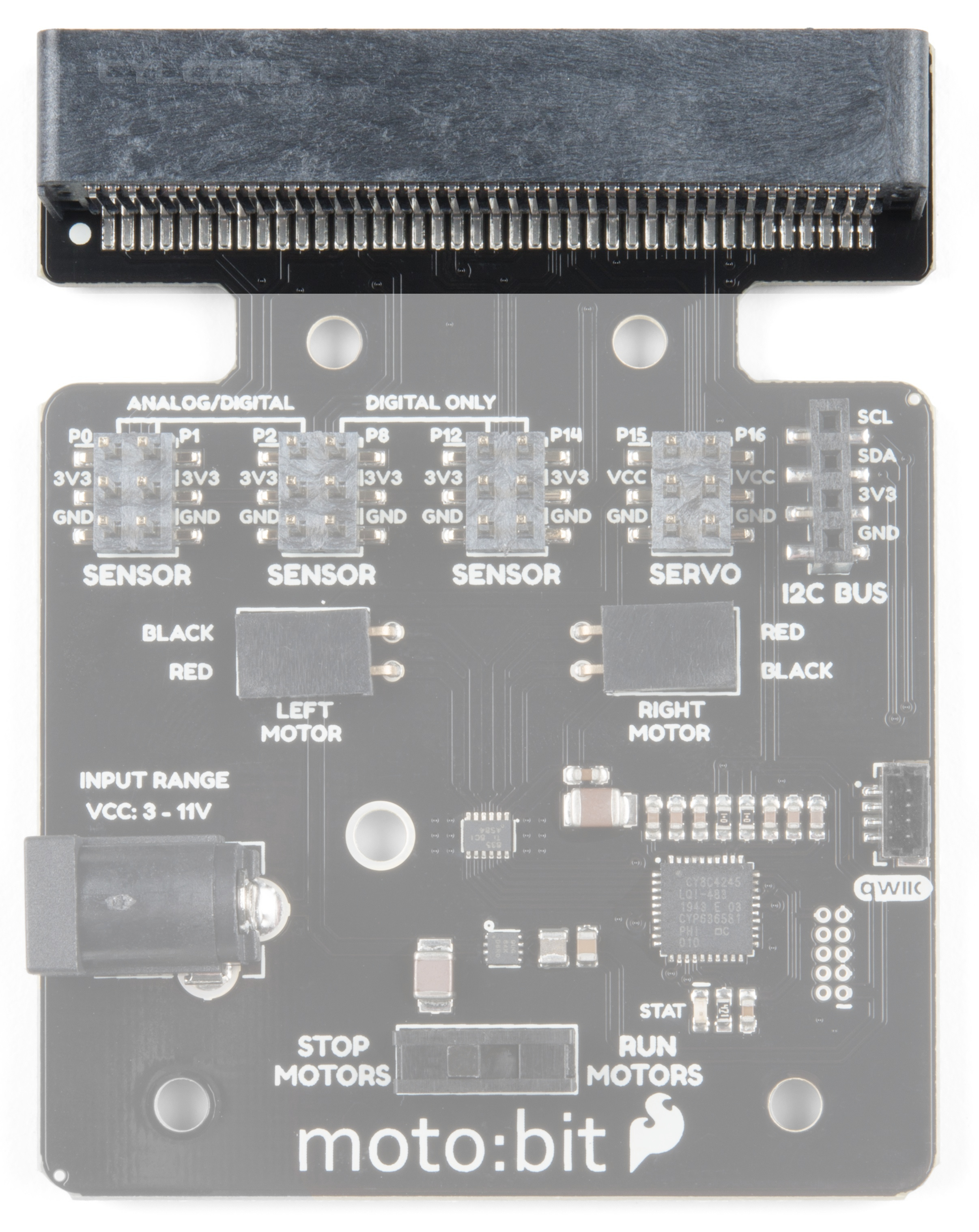
About the moto:bit Board
The moto:bit is a carrier board for the micro:bit. Similar to an Arudino shield, it is designed to add functionality to
the micro:bit without the hassle of a number of other boards, soldering, and all of those jumper wires.
In this case, the moto:bit takes a micro:bit and turns it into a full blown robotics platform. Wondering what you can
do with it? Well here are a few things...
Control motors through an onboard H-Bridge
Read digital sensors such as line and bump sensors
Read analog sensors like light sensors, temperature sensors, etc
Getting Started with the micro:bit
The BBC micro:bit is a compact, powerful programming
tool that requires no software installation. Read on to
learn how to use it YOUR way!
SparkFun moto:bit - micro:bit Carrier Board (Qwiic)
DEV-15713

Control servo motors
I C port for extending functionality
That is a lot of options in terms of bells and whistles! Let's take a closer look at the board and go over each
section.
Note: If you have the previous version of this board (DEV-14213), note that the functionality is, for all
intents and purposes, the same. Version 2.0 just has an upgraded micro:bit connector and a Qwiic connector
to bring this board into our Qwiic eco-system. You should be able to use the original moto:bit board in the
same manner as the revised board is used in the rest of this experiment guide!
Qwiic moto:bit [ DEV-15713 ] moto:bit [ DEV-14213 ]
Edge Connector
The moto:bit connects to the micro:bit via an edge pin connector. This makes it handy to swap out micro:bits for
programming, and it creates reliable connections to all of the different pins on the micro:bit.
2

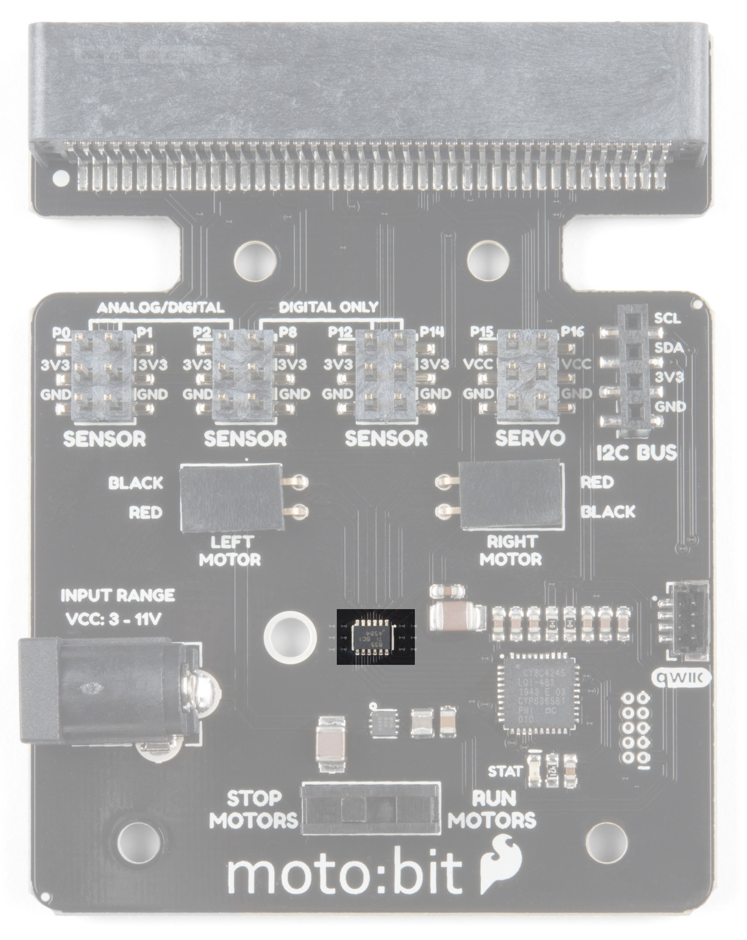
H-Bridge and Motor Pins
An H-Bridge is a chip that is the heart of a robot when it comes to driving motors and more specifically driving
motors in both directions. Depending on the electrical state of specific pins on the H-Bridge, a motor drives
forwards, backwards, and at different speeds. The good thing about this board is that if you are using Microsoft
MakeCode, you actually don't really need to know a whole lot about the H-Bridge itself.
To connect the hobby motors that are included in the kit, you can insert them into the 2-pin female connectors just
above the motor pins. The connectors are highlighted in the image below. Keep in mind that direction the hobby
motors will move depends on the code to control the H-bridge motor driver, how the motors are attached to a

chassis, and the way the motors are wired to the input pins.
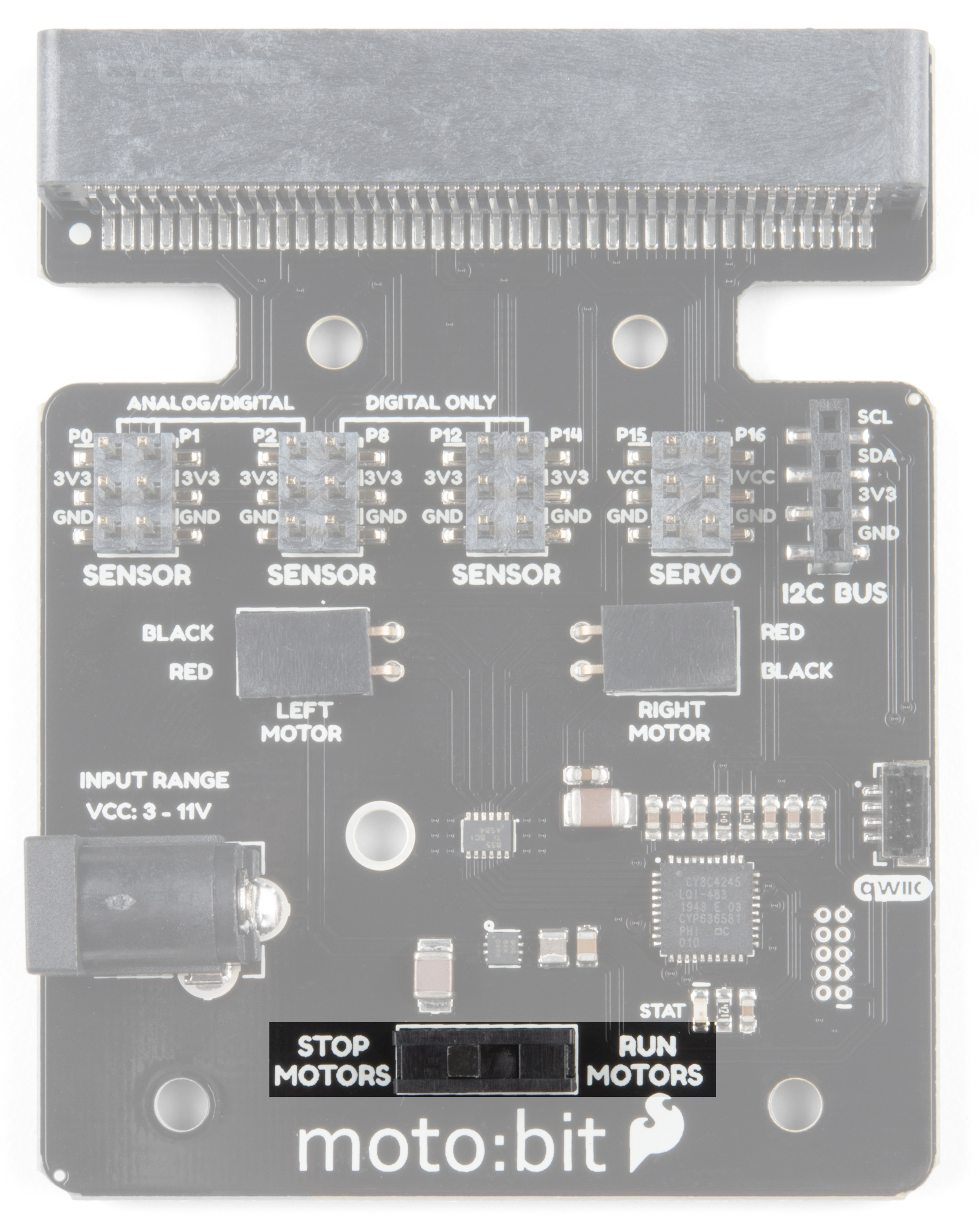
Motor Control Switch
The moto:bit has a switch that controls the power supply to the motors. That way you can have the robot powered
while working on it or programming it and know that the robot is not going to start moving and drive off of the table.
Believe us... that happens all the time!
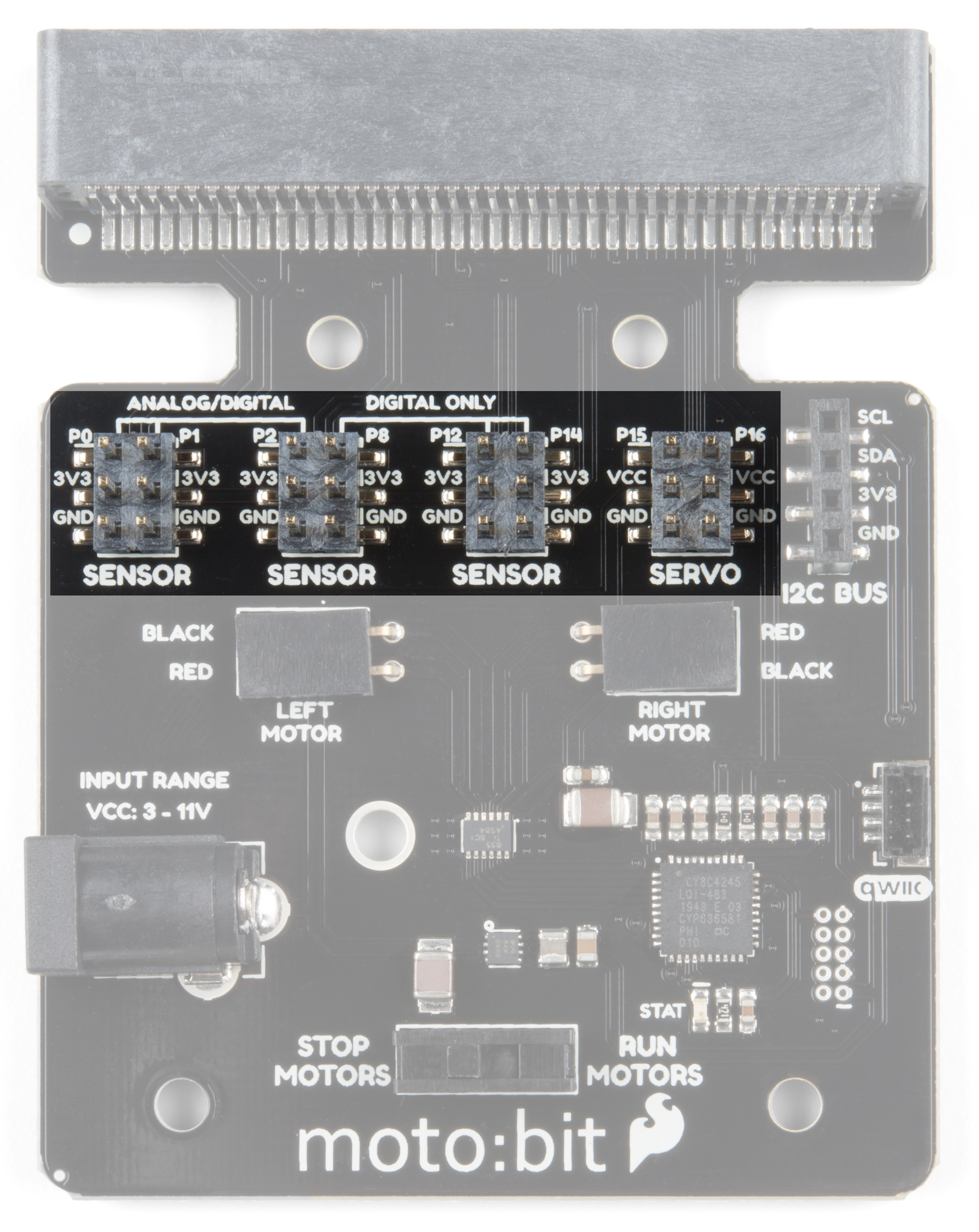
Input and Output Pins

The male pins on the moto:bit are for hooking up various inputs and outputs on your robot without using a
breadboard to build elaborate circuits.
We have a number of sensors and actuators that are built in this pin formation and will work with this board.
SparkFun Line Follower Array
SEN-13582
Wheel Encoder Kit
ROB-12629
SparkFun RedBot Sensor - Mechanical Bumper
SEN-11999
SparkFun RedBot Buzzer
ROB-12567

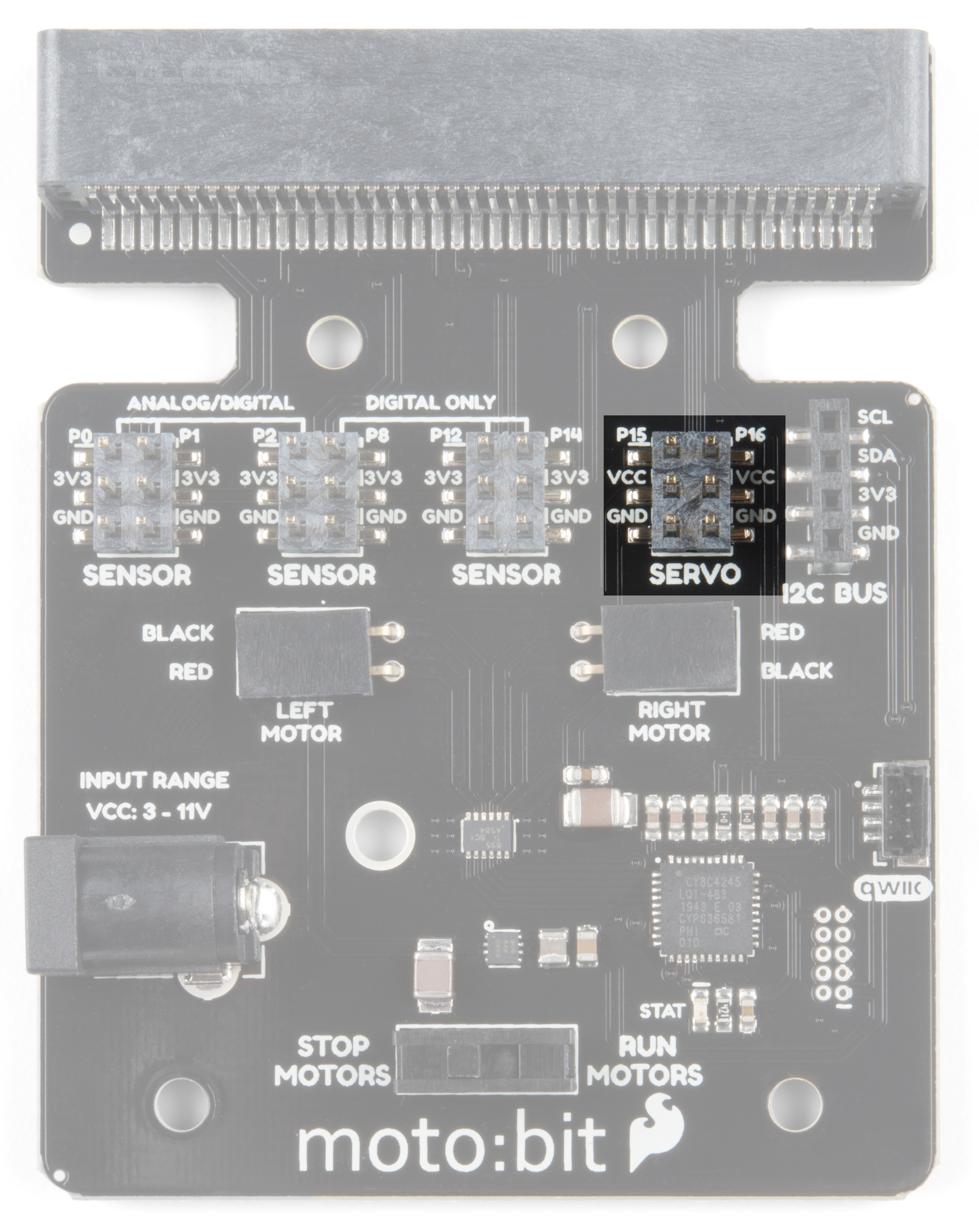
Servo Ports
No robot is complete without an arm, a swiveling "head," or some other type of movement other than wheels.
Notice that a couple of the pin groups are designated as "Servo". You can connect servo motors directly to these
pins and use them right out of the box with Microsoft MakeCode.
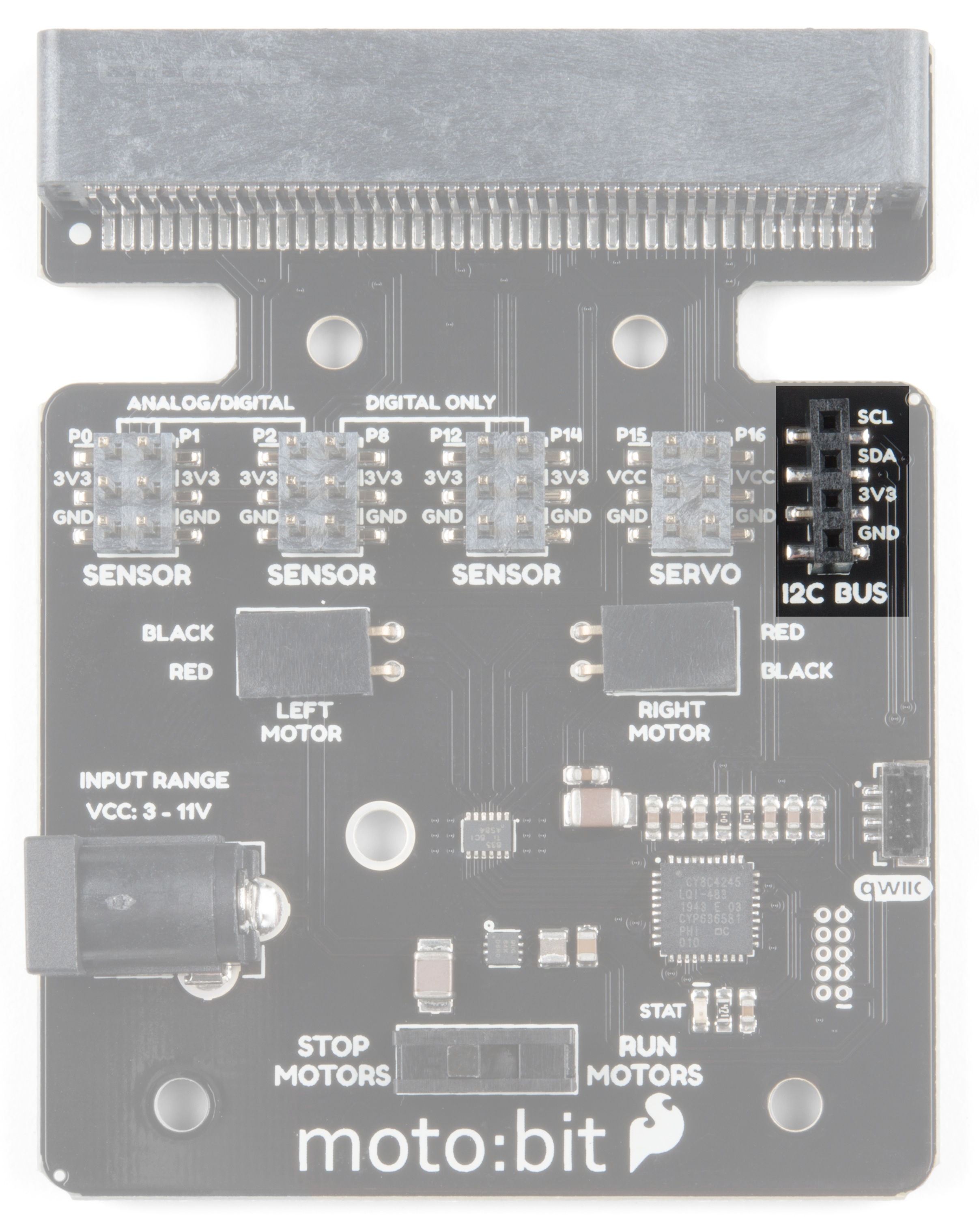
I C Port
We broke out the I C port of the micro:bit to an external port so that you can add any I C capable sensor or
actuator you can think of. It is standard pin arrangement to many of our I C sensor breakout boards.
SparkFun RedBot Sensor - Accelerometer
SEN-12589
2
2 2
2

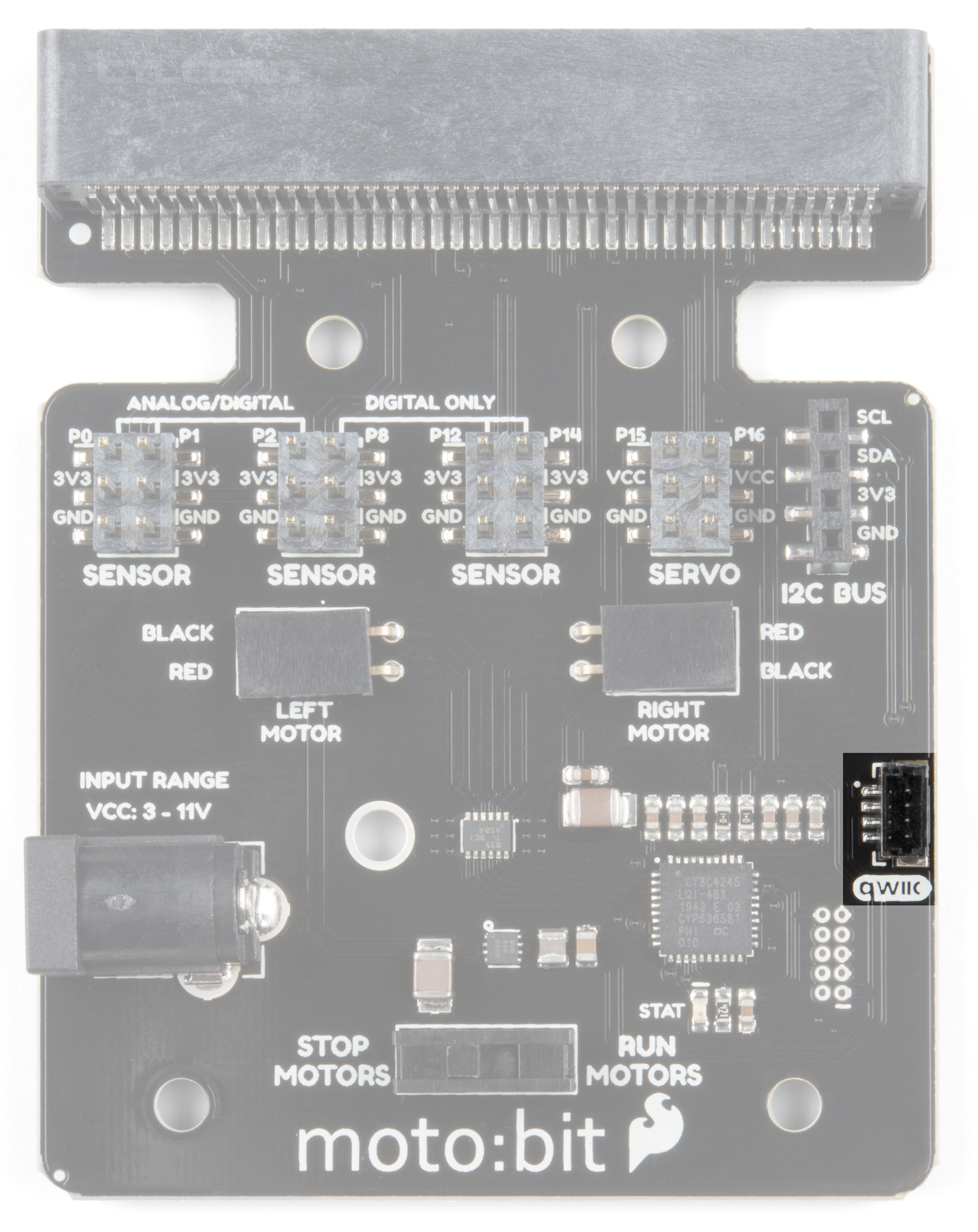
Qwiic Connector
With the updated moto:bit board, we've added a Qwiic connector so that our Qwiic line of products can be
incorporated more easily.
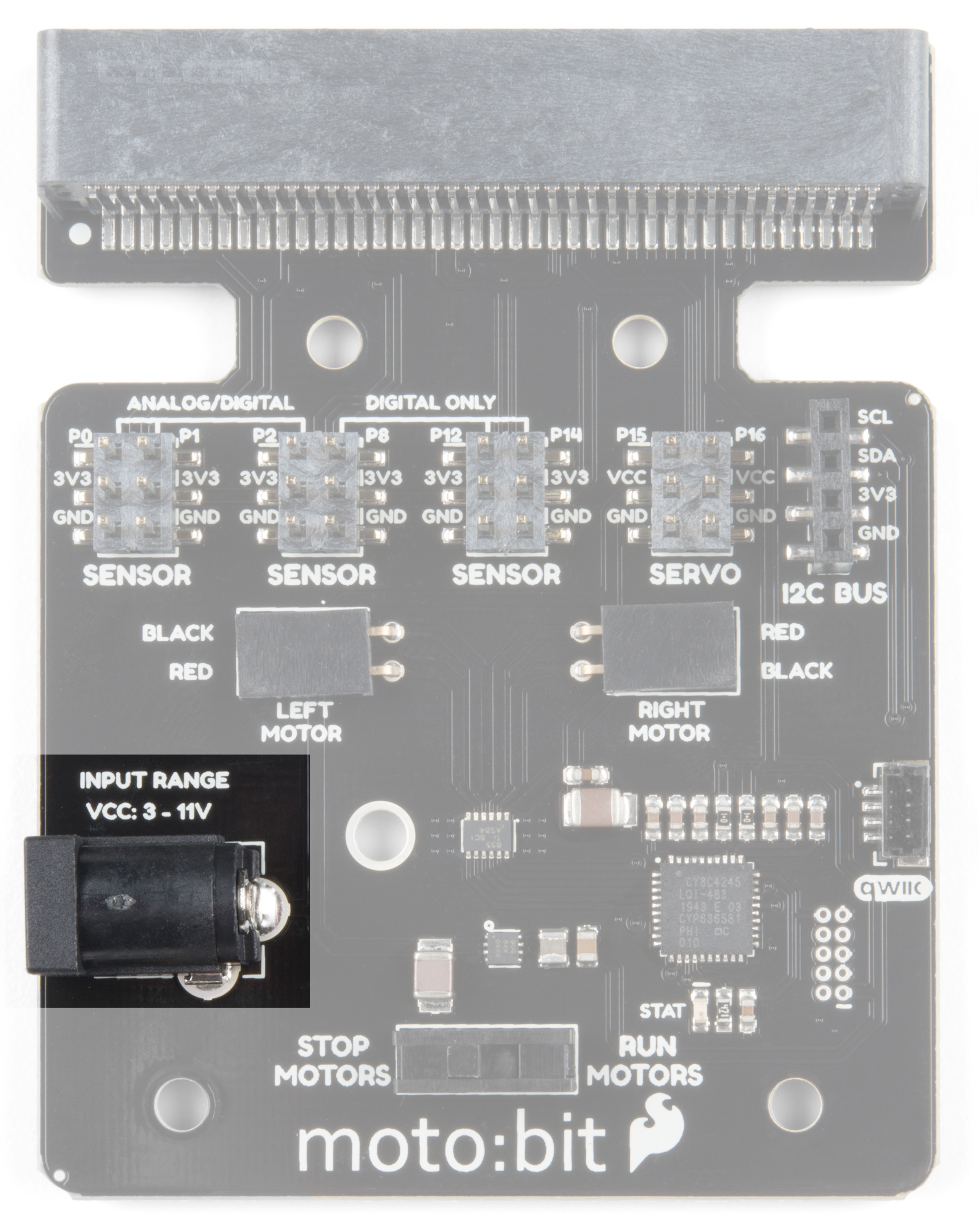
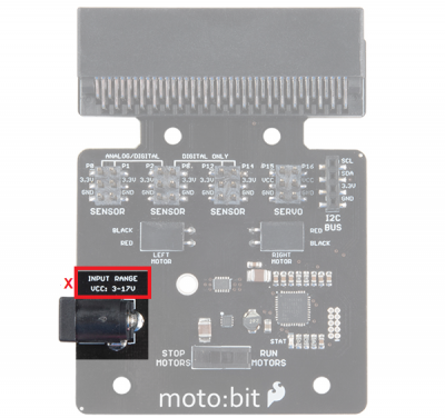
Power
A standard barrel jack connector is used for easily powering your robot. We find that a 4xAA battery pack works
great, but it will accept between 3V-11V at the barrel jack. That's a whole lot of robo-power!

Maximum Input Voltage Range for Vcc: If you have the previous version of this board, the silkscreen
indicates that the maximum input voltage range is between 3V to 17V. However, the actual voltage range that
the board can support through the barrel jack is between 3V to 11V. Please do not apply more than 11V to
the power jack on the moto:bit. The updated version of this board lists the maximum input voltage correctly.
Assembling Your Robot
This section will cover how to assemble your robot chassis. Assembly time: 30-60 minutes
The robot chassis requires the following pieces to build. You'll find most of them in your SparkFun micro:bot kit.
Note: Several of the parts need to be snapped out of the main chassis panels.

Click on the image for a closer look.
Letter Part Qty
A Bottom Chassis Plate 1
B Top Chassis Plate 1
C Front Motor Mount 2
D Rear Motor Mount 2
E Side Strut 4
F Encoder Mount (Not Used in this Guide) 2
G moto:bit Mount 2
H Battery Pack Clip 1
I Line Follower Mount 1
J Line Follower Mount Plate 1
K Jumper Wire — 3-pin, 6" 3
L Wheels 2
M Nub Caster 1
N DC Motors 2
O Line Follower Boards 3
P 4xAA Battery Holder 1
Q 4xAA Batteries (Not Included) 3
No Tools Necessary
The robot chassis does not require any additional tools.

WARNING: Do not attempt to remove chassis parts by squeezing them with pliers. If you try to muscle it too
much you risk breaking them and compromising the structure of your robot. Handle with care. ;)
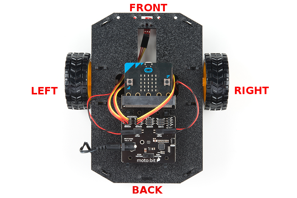
A Note About Orientation
When we talk about the "front," "left," "right," and "back" of the Shadow Chassis, we are referring to specific sides
of the robot when viewed from above.
Notice that we consider the SparkFun moto:bit to be on the "back" of the bot and the Bumper Whiskers and Line
Follower Boards to be in the "front."
Assembly
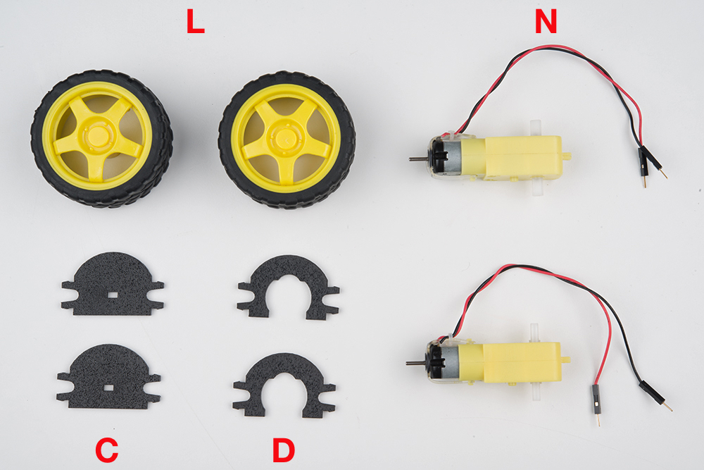
Installing Motors
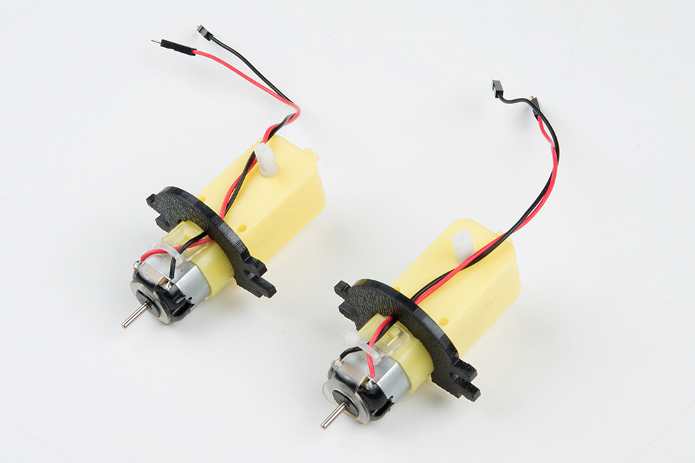
Let's begin by installing the motors that will control the wheels. Locate the following:

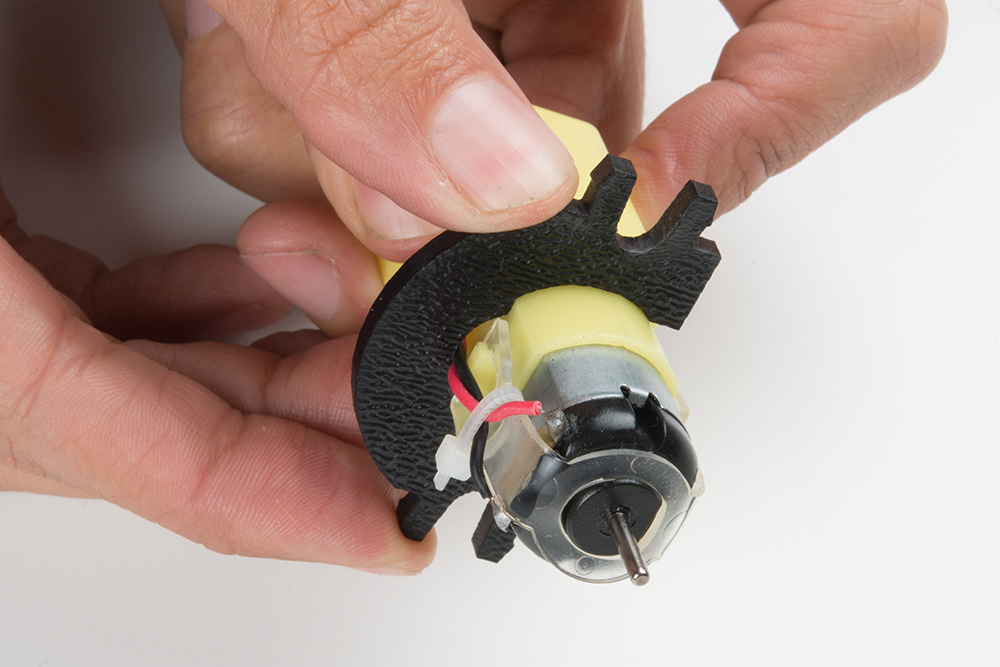
Attach Rear Motor Mounts
Hold the wires near the middle of the Motor (N), and carefully slide a Rear Motor Mount (D) in from the side and
over the two motor wires. Be careful not to snag the wires, the cable tie, or the clear plastic strap.
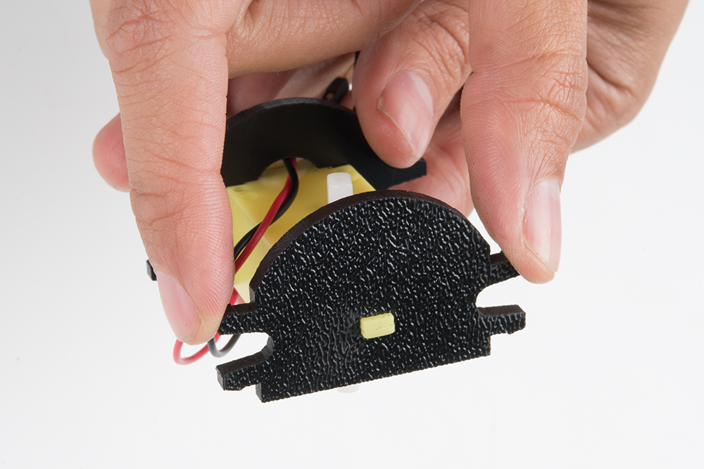
Holding the motor wires, gently twist the Rear Motor Mount counter clockwise so that it snaps in place on the
motor and the wires are centered in the gap of the motor mount. Again, be sure not to snag the wires under the
motor mount.
Repeat the process for the second motor, ensuring that it is a mirror image of the first.
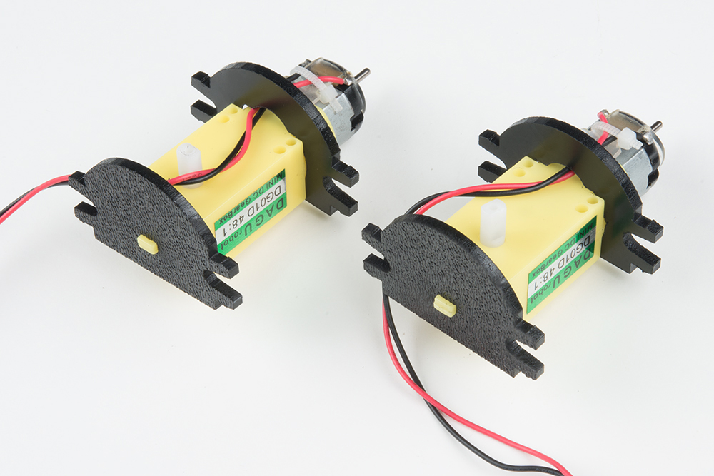
Attach the Front Motor Mounts
Slide a Front Motor Mount (C) onto the protruding eyelet on the front of a Motor (N). Ensure the rounded sides of
the motor mounts are facing the same way.

Repeat the process for the second motor.
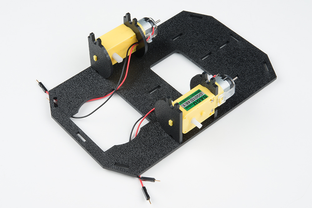
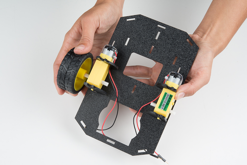
Attach the Motor Assemblies to the Chassis
Snap one of the motor assemblies into the left two horizontal slots of the Bottom Chassis Plate (A). Make sure that
the rounded edges of the motor mounts and the wires are facing toward the center of the chassis. Repeat for the
opposite motor.
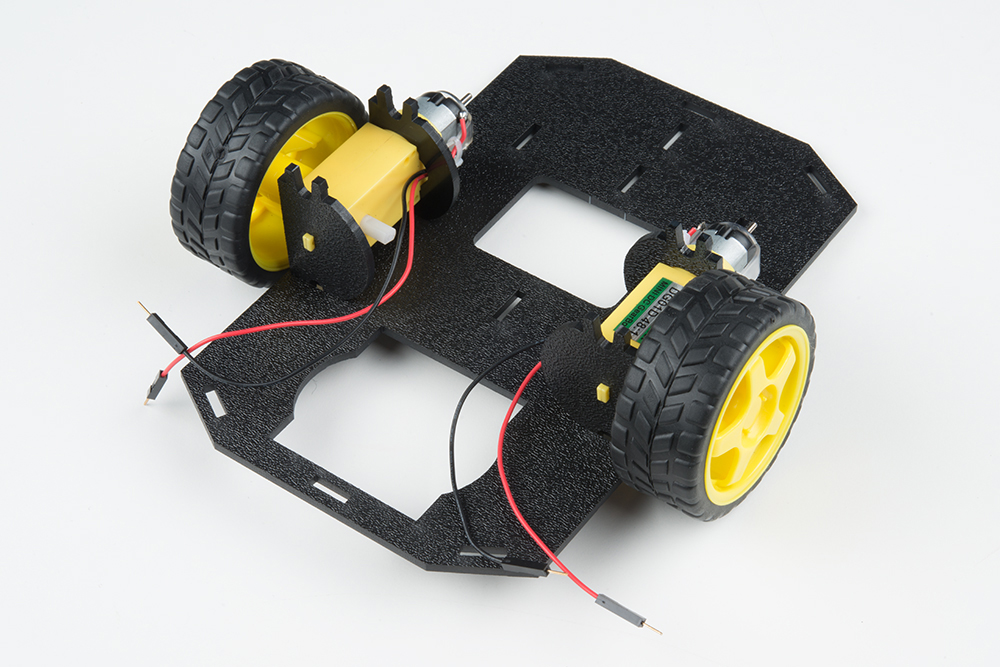
Attach the Wheels
Slide one Wheel (L) onto the plastic shaft of a Motor (N). Look at the motor shaft. Notice it has two flat edges.
Make sure to line up the flat edges of the motor shaft with the flat edges of the wheel.

Repeat with the other wheel.
Installing the Line Sensors
This section will cover the Line Following Sensors array assembly. You'll first build the Line Following array and
then attach it to the chassis. Locate the following:
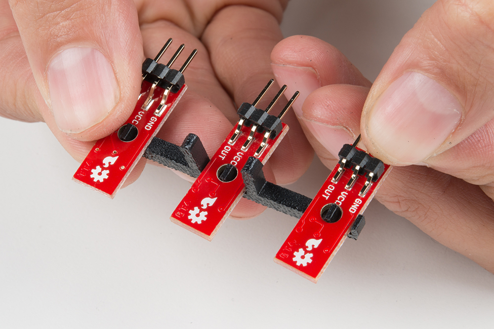
Construct the Line Follower Assembly
Attach the three Line Follower Boards (O) to the Line Follower Mount (I) such that the rectangular pegs in the Line
Follower Mount poke through the mounting holes in the Line Follower Boards. Make sure the sensors are facing
away/down from the clip of the mount.

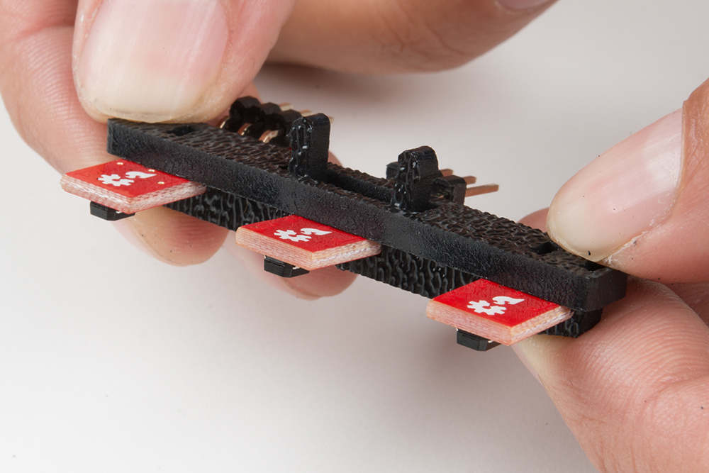
Place the Line Follower Mount Plate (J) on top of the Line Follower Mount (I) so that the center clip of the mount is
poking through the center slot of the plate.
Attach the Cables
You will need to connect a 3-Wire Jumper Cable (K) to each of the Line Follower Boards (O). Note the color of the
wire attached to each pin.
Line Follower Connections:
Jumper Wire Color RedBot Sensor - Line Follower
Red GND
Orange VCC
Yellow OUT
Attach all 3 cables to the 3 Line Follower Boards. Notice that the yellow wire should be on the right (out) and the
red wire should be on the left (ground).

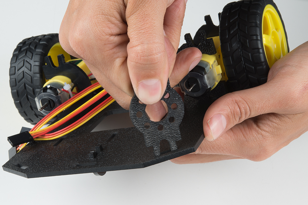
Attach the Line Follower Assembly to the Chassis
Locate the wide, rectangular slot near the front of the chassis and snap the line follower assembly in from the
bottom side of the chassis. Route the cables through the large hole in the bottom plate.
The bottom of your chassis should look like the following image allowing the line sensors to be facing down.
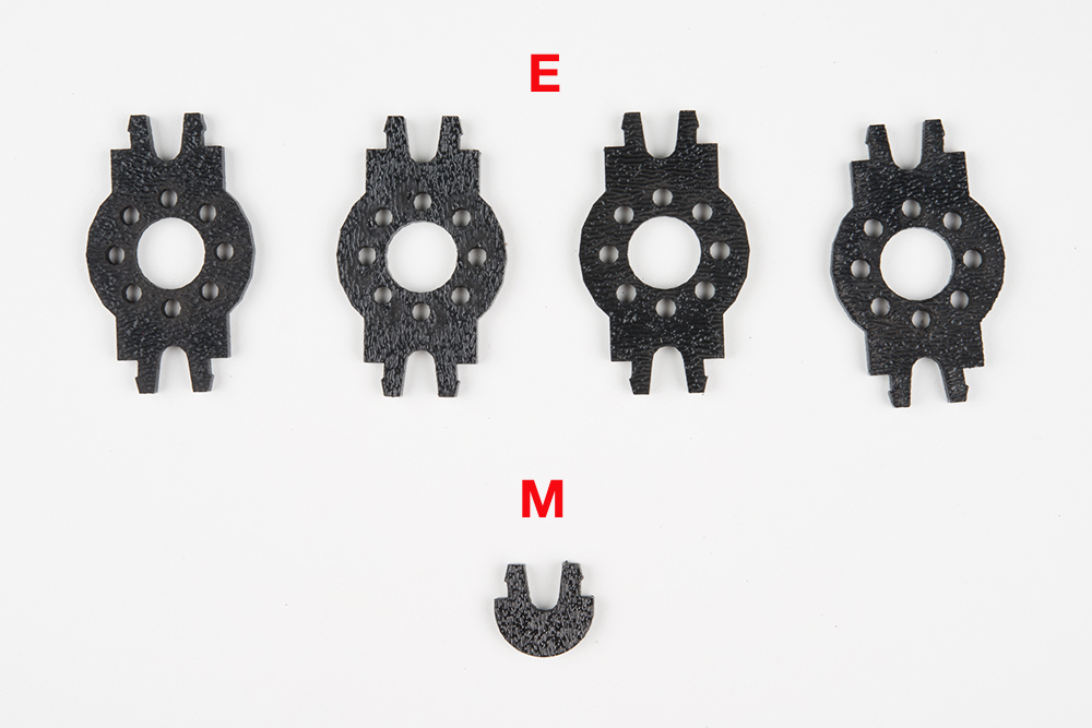
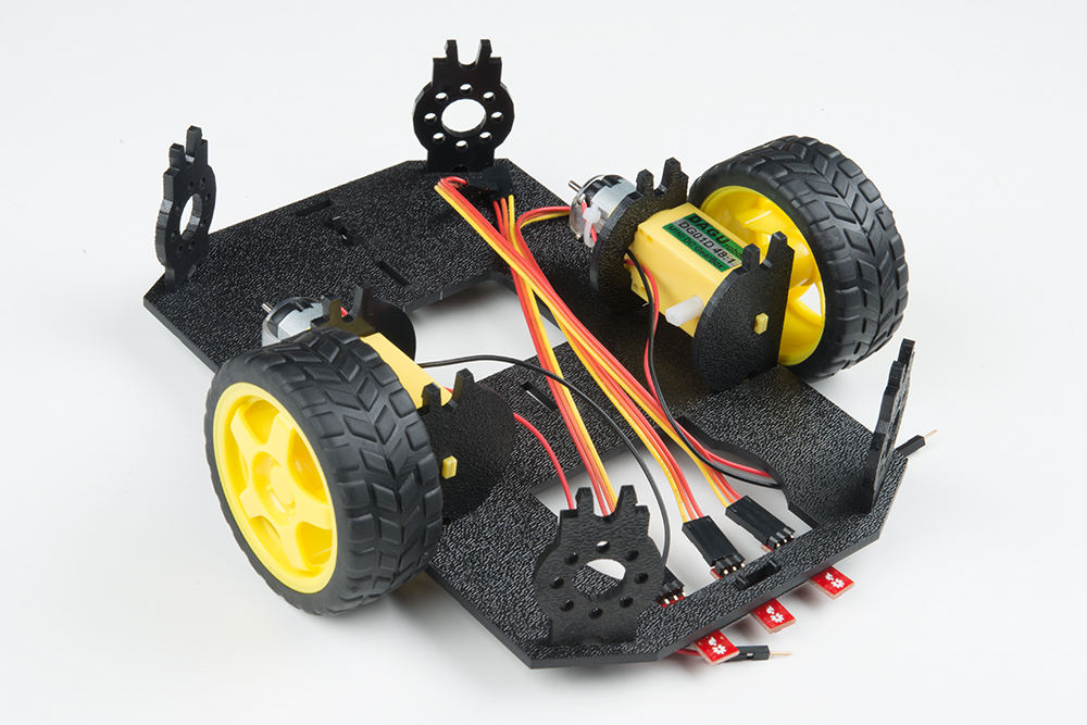
Final Assembly
With the motors and a few sensors attached, we can assemble the main body of the robot. Locate the following:

You will also need the Top Chassis Plate and Bottom Chassis Plate assemblies, which have any additional
parts and sensors you attached in previous steps.
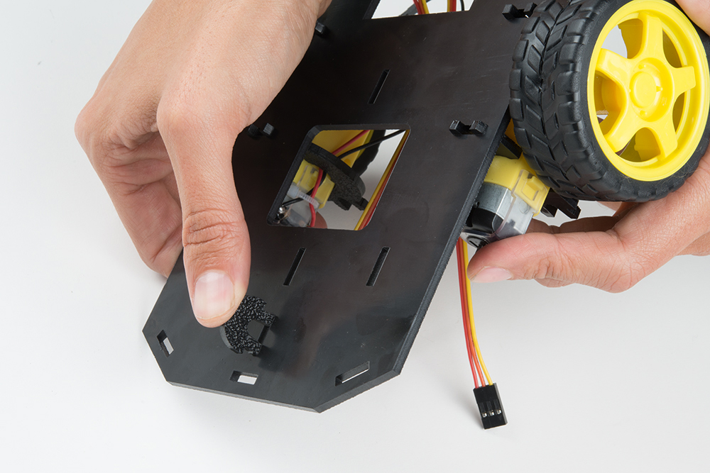
Attach the Nub Caster
Snap the Nub Caster (M) into the slot on the back of the Bottom Chassis Plate assembly. Make sure the Nub
Caster is on the side opposite the motors (the bottom side).
Add the Side Struts
Snap the four Side Struts (E) into the diagonal slots on the four corners of the Bottom Chassis Plate assembly.
Pull the cables through the cutouts on the chassis.

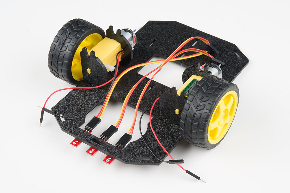
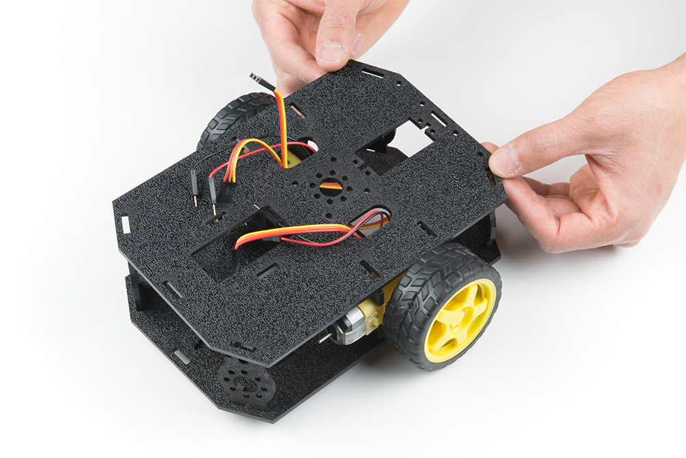
Route the Cables
Position the Top Chassis Plate over the Bottom Chassis Plate -- but do not snap the two plates together yet. Make
sure that the front sides of each plate line up.
Route the wires and cables through the left and right oval slots in the Top Chassis Plate assembly as shown. For
the center line follower sensor, route this cable through the left oval slot.
NOTE: It might be a good idea to use some pieces of masking tape to mark which cables go to which
component. It's not necessary, but it might help keep things organized.
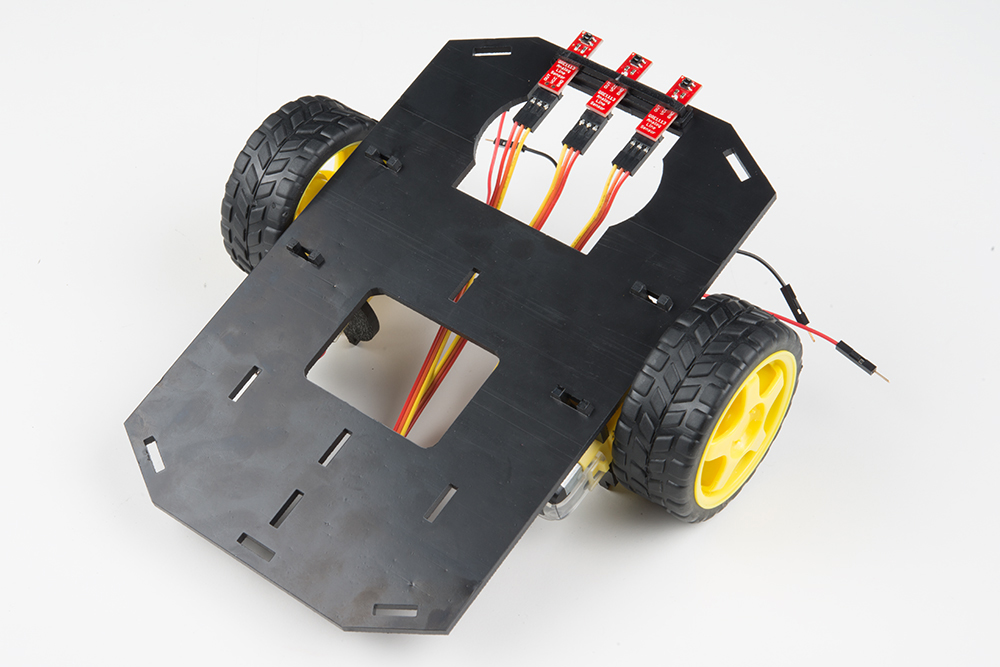
Cable Routing:
Cable Connection Oval Side
Left Line Follower Left
Center Line Follower Left
Right Line Follower Right
Left Motor Wires (red and black) Left
Right Motor Wires (red and black) Right
Attach Top Chassis Plate Assembly
Table of contents
Other sparkfun Carrier Board manuals


