TQ MB-COME6-4 User manual

User's Manual l MB-COME6-4 UM 0100 l © 2022, TQ-Systems GmbH Page i
MB-COME6-4
User's Manual
MB-COME6-4 UM 0100
15.03.2022

User's Manual l MB-COME6-4 UM 0100 l © 2022, TQ-Systems GmbH Page i
TABLE OF CONTENTS
1. ABOUT THIS MANUAL.................................................................................................................................................................1
1.1 Copyright and Licence Expenses.............................................................................................................................................1
1.2 Registered Trademarks...............................................................................................................................................................1
1.3 Disclaimer .......................................................................................................................................................................................1
1.4 Imprint .............................................................................................................................................................................................1
1.5 Service and Support ....................................................................................................................................................................1
1.6 Tips on Safety.................................................................................................................................................................................2
1.7 Symbols and Typographic Conventions ...............................................................................................................................2
1.8 Handling and ESD Tips................................................................................................................................................................2
1.9 Naming of Signals ........................................................................................................................................................................3
1.10 Further Applicable Documents / Presumed Knowledge .................................................................................................3
2. INTRODUCTION.............................................................................................................................................................................4
2.1 Functional Overview ...................................................................................................................................................................4
2.2 Specification Compliance ..........................................................................................................................................................5
2.3 Carrier Board Standard Configurations .................................................................................................................................5
2.4 Accessories .....................................................................................................................................................................................5
3. FUNCTION.......................................................................................................................................................................................6
3.1 Block Diagram ...............................................................................................................................................................................6
3.2 Electrical Specification................................................................................................................................................................7
3.2.1 Supply Voltage Characteristics.................................................................................................................................................7
3.2.2 Power Consumption Specification .........................................................................................................................................7
3.3 Environmental Specification.....................................................................................................................................................7
3.4 System Components...................................................................................................................................................................7
3.4.1 Gigabit Ethernet Controller.......................................................................................................................................................7
3.4.2 HD-Audio Controller....................................................................................................................................................................7
3.5 Connectors and Interfaces.........................................................................................................................................................8
3.5.1 Power Supply.............................................................................................................................................................................. 10
3.5.2 DisplayPort .................................................................................................................................................................................. 10
3.5.3 USB Host Interfaces................................................................................................................................................................... 11
3.5.4 Gigabit Ethernet......................................................................................................................................................................... 11
3.5.5 Serial Interface (RS-232)........................................................................................................................................................... 12
3.5.6 Embedded Display Port........................................................................................................................................................... 13
3.5.7 LVDS .............................................................................................................................................................................................. 14
3.5.8 M.2 socket with M Key (for PCIe SSD devices) .................................................................................................................. 15
3.5.9 M.2 socket with M Key (for PCIe SSD devices) .................................................................................................................. 15
3.5.10 M.2 socket with B Key (for WWAN modules or SATA SSD devices)............................................................................ 15
3.5.11 M.2 socket with E Key (for I/O devices)............................................................................................................................... 15
3.5.12 SATA Interfaces .......................................................................................................................................................................... 16
3.5.13 Audio............................................................................................................................................................................................. 16
3.5.14 Fan Connector............................................................................................................................................................................ 16
3.5.15 PCI Express Connector............................................................................................................................................................. 16
3.5.16 Feature Connector .................................................................................................................................................................... 17
3.5.17 Debug LEDs................................................................................................................................................................................. 18
3.5.18 SPI Flash Socket.......................................................................................................................................................................... 18
3.5.19 COM Express™ Connector....................................................................................................................................................... 18
3.6 Buttons ......................................................................................................................................................................................... 18
3.6.1 Reset Button................................................................................................................................................................................ 18
3.6.2 Power Button.............................................................................................................................................................................. 18
4. MECHANICS................................................................................................................................................................................. 19
4.1 Dimensions.................................................................................................................................................................................. 19
4.2 Protection Against External Effects...................................................................................................................................... 19
4.3 Labeling........................................................................................................................................................................................ 20
5. SOFTWARE................................................................................................................................................................................... 21
5.1 System Resources...................................................................................................................................................................... 21
5.1.1 I2C Bus ........................................................................................................................................................................................... 21
5.1.2 SMBus............................................................................................................................................................................................ 21
5.2 Driver Download........................................................................................................................................................................ 21
6. SAFETY REQUIREMENTS AND PROTECTIVE REGULATIONS .......................................................................................... 22
6.1 EMC................................................................................................................................................................................................ 22
6.2 ESD................................................................................................................................................................................................. 22
6.3 Operational Safety and Personal Security ......................................................................................................................... 22
6.4 Reliability and Service Life ...................................................................................................................................................... 22
6.4.1 RoHS .............................................................................................................................................................................................. 22

User's Manual l MB-COME6-4 UM 0100 l © 2022, TQ-Systems GmbH Page ii
6.5 WEEE®............................................................................................................................................................................................ 22
6.6 REACH®......................................................................................................................................................................................... 22
6.7 EuP ................................................................................................................................................................................................. 22
6.8 Battery........................................................................................................................................................................................... 22
6.9 Packaging .................................................................................................................................................................................... 22
6.10 Other Entries ............................................................................................................................................................................... 23
7. APPENDIX..................................................................................................................................................................................... 24
7.1 Acronyms and Definitions ...................................................................................................................................................... 24
7.2 References ................................................................................................................................................................................... 26
TABLE DIRECTORY
Table 1: Terms and Conventions .............................................................................................................................................................2
Table 2: Power-In Connector.................................................................................................................................................................. 10
Table 3: USB 2.0 Host Extension Connectors .................................................................................................................................... 11
Table 4: Ethernet LEDs ............................................................................................................................................................................. 11
Table 5: Serial Port COM Express™ Port Mapping............................................................................................................................ 12
Table 6: Serial Port RS-232 pinout via cable to 9-pin D-Sub......................................................................................................... 12
Table 7: eDP Connector ........................................................................................................................................................................... 13
Table 8: LVDS Connector......................................................................................................................................................................... 14
Table 9: Backlight Connector................................................................................................................................................................. 15
Table 10: Fan Connector............................................................................................................................................................................ 16
Table 11: GPIO and COME Signal Connector X20 .............................................................................................................................. 17
Table 12: I2C and COME Signal Connector X21................................................................................................................................... 17
Table 13: Debug LEDs................................................................................................................................................................................. 18
Table 14: Labels on MB-COME6-4 ........................................................................................................................................................... 20
Table 15: I2C Address Mapping................................................................................................................................................................ 21
Table 16: Acronyms..................................................................................................................................................................................... 24
Table 17: Further Applicable Documents and Links ......................................................................................................................... 26
FIGURE DIRECTORY
Figure 1: MB-COME6-4 Block Diagram ....................................................................................................................................................6
Figure 2:MB-COME6-4 Top view...............................................................................................................................................................8
Figure 3:MB-COME6-4 Bottom view.......................................................................................................................................................9
Figure 4:RJ45 Connectors ........................................................................................................................................................................ 11
Figure 5:10-pin RS232 Connector ......................................................................................................................................................... 12
Figure 6:eDP Connector ........................................................................................................................................................................... 13
Figure 7:Config Switch: eDP / LVDS...................................................................................................................................................... 13
Figure 8:LVDS Connector......................................................................................................................................................................... 14
Figure 9: Backlight Connector................................................................................................................................................................. 15
Figure 10:Audio Connectors X12, X13, X14 .......................................................................................................................................... 16
Figure 11:Fan Connector............................................................................................................................................................................ 16
Figure 12:Feature Connectors .................................................................................................................................................................. 17
Figure 13:SPI socket and BIOS_DIS1# Jumper..................................................................................................................................... 18
Figure 14:MB-COME6-4 Dimensions....................................................................................................................................................... 19
Figure 15: Position of labels........................................................................................................................................................................ 20
REVISION HISTORY
Rev. Date Name Pos. Modification
0100 15.03.2022 Probst First edition

User's Manual l MB-COME6-4 UM 0100 l © 2022, TQ-Systems GmbH Page 1
1.
ABOUT THIS MANUAL
1.1
Copyright and Licence Expenses
Copyright protected © 2022 by TQ-Systems GmbH.
This User's Manual may not be copied, reproduced, translated, changed or distributed, completely or partially
in electronic, machine readable, or in any other form without the written consent of TQ-Systems GmbH.
The drivers and utilities for the components used as well as the BIOS are subject to the copyrights of the respective
manufacturers. The licence conditions of the respective manufacturer are to be adhered to.
BIOS-licence expenses are paid by TQ-Systems GmbH and are included in the price.
Licence expenses for the operating system and applications are not taken into consideration and must be calculated / declared
separately.
1.2
Registered Trademarks
TQ-Systems GmbH aims to adhere to copyrights of all graphics and texts used in all publications, and strives to use original
or license-free graphics and texts.
All brand names and trademarks mentioned in this User's Manual, including those protected by a third party, unless specified
otherwise in writing, are subjected to the specifications of the current copyright laws and the proprietary laws of the present
registered proprietor without any limitation. One should conclude that brand and trademarks are rightly protected by a third
party.
1.3
Disclaimer
TQ-Systems GmbH does not guarantee that the information in this User's Manual is up-to-date, correct, complete or of good
quality. Nor does TQ-Systems GmbH assume guarantee for further usage of the information. Liability claims against TQ-Systems
GmbH, referring to material or non-material related damages caused, due to usage or non-usage of the information given in this
User's Manual, or due to usage of erroneous or incomplete information, are exempted, as long as there is no proven intentional
or negligent fault of TQ-Systems GmbH.
TQ-Systems GmbH explicitly reserves the rights to change or add to the contents of this User's Manual or parts of it without
special notification.
1.4
Imprint
TQ-Systems GmbH
Gut Delling, Mühlstraße 2
D-82229 Seefeld
Tel: +49 8153 9308–0
Fax: +49 8153 9308–4223
E-Mail: Info@TQ-Group
Web: TQ-Group
1.5
Service and Support
Please visit our website www.tq-group.com for latest product documentation, drivers, utilities and technical support.
You can register on our website www.tq-group.com to have access to restricted information and automatic update services.
For direct technical support you can contact our FAE team by email: support@tq-group.com.
Our FAE team can also support you with additional information like 3D-STEP files and confidential information, which is not
provided on our public website.
For service/RMA, please contact our service team by email (service@tq-group.com) or your sales team at TQ.

User's Manual l MB-COME6-4 UM 0100 l © 2022, TQ-Systems GmbH Page 2
1.6
Tips on Safety
Improper or incorrect handling of the product can substantially reduce its life span.
1.7
Symbols and Typographic Conventions
Table 1: Terms and Conventions
Symbol Meaning
This symbol represents the handling of electrostatic-sensitive modules and / or components. These
components are often damaged / destroyed by the transmission of a voltage higher than about 50 V.
A human body usually only experiences electrostatic discharges above approximately 3,000 V.
This symbol indicates the possible use of voltages higher than 24 V.
Please note the relevant statutory regulations in this regard.
Non-compliance with these regulations can lead to serious damage to your health and also cause
damage / destruction of the component.
This symbol indicates a possible source of danger. Acting against the procedure described can lead to
possible damage to your health and / or cause damage / destruction of the material used.
This symbol represents important details or aspects for working with TQ-products.
Command
A font with fixed width denotes commands, contents, file names, or menu items.
1.8
Handling and ESD Tips
General handling of your TQ-products
The TQ-product may only be used and serviced by certified personnel who have taken note of the
information, the safety regulations in this document and all related rules and regulations.
A general rule is: do not touch the TQ-product during operation. This is especially important when
switching on, changing jumper settings or connecting other devices without ensuring beforehand
that the power supply of the system has been switched off.
Violation of this guideline may result in damage / destruction of the MB-COME6-4 module and be
dangerous to your health.
Improper handling of your TQ-product would render the guarantee invalid.
Proper ESD handling
The electronic components of your TQ-product are sensitive to electrostatic discharge (ESD).
Always wear antistatic clothing, use ESD-safe tools, packing materials etc., and operate your TQ-
product in an ESD-safe environment. Especially when you switch modules on, change jumper settings,
or connect other devices.

User's Manual l MB-COME6-4 UM 0100 l © 2022, TQ-Systems GmbH Page 3
1.9
Naming of Signals
A hash mark (#) at the end of the signal name indicates a low-active signal.
Example: RESET#
If a signal can switch between two functions and if this is noted in the name of the signal, the low-active function is marked with
a hash mark and shown at the end.
Example: C / D#
If a signal has multiple functions, the individual functions are separated by slashes when they are important for the wiring.
The identification of the individual functions follows the above conventions.
Example: WE2# / OE#
1.10
Further Applicable Documents / Presumed Knowledge
•
Specifications and manual of the modules used:
These documents describe the service, functionality and special characteristics of the module used.
•
Specifications of the components used:
The manufacturer's specifications of the components used, for example CompactFlash cards, are to be taken note of.
They contain, if applicable, additional information that must be taken note of for safe and reliable operation.
These documents are stored at TQ-Systems GmbH.
•
Chip errata:
It is the user's responsibility to make sure all errata published by the manufacturer of each component are taken note of.
The manufacturer’s advice should be followed.
•
Software behaviour:
No warranty can be given, nor responsibility taken for any unexpected software behaviour due to deficient components.
•
General expertise:
Expertise in electrical engineering / computer engineering is required for the installation and the use of the device.
Implementation information for the carrier board design is provided in the COM Express™ Design Guide (2) maintained by the
PICMG®. This Carrier Design Guide includes a very good guideline to design a COM Express™ carrier board.
It includes detailed information with schematics and detailed layout guidelines.
Please refer to the official PICMG®documentation for additional information (1), (2).

User's Manual l MB-COME6-4 UM 0100 l © 2022, TQ-Systems GmbH Page 4
2.
INTRODUCTION
The COM Express™ mainboard MB-COME6-4 is a carrier board for COM Express™ modules with Type 6 pinout.
It can be used for panel PCs, embedded computers or as an evaluation platform for COM Express™ modules.
In combination with a standard COM Express™ module it forms a very compact hardware kit that can be used for a freely scalable
embedded PC platform. Because of this – with uniform interfaces and dimensions – the PC system can be easily adapted to suit
the requirements of the application. The wide range of extension options and storage media, which can be added, offer a high
level of flexibility and allow functionalities and performance to be extended easily, quickly and inexpensively.
Typical usage is in embedded server applications, PC systems for automation, visualisation and monitoring and all applications
that place high demands on quality, durability and long-term availability.
2.1
Functional Overview
The following key functions are implemented on the MB-COME6-4:
Supported Modules:
•COM Express™ Compact / Basic Modules with Type 6 pinout (COM.0 R3.0)
External Interfaces:
•2 x 2.5 Gigabit Ethernet
•2 x USB 3.2 Gen 2 Type A connector with USB 3.0 compatibility
•1 x USB 3.2 Gen 2 Type C connector with USB 3.0 compatibility
•3 x DisplayPort (DP++) connectors
•3 x Audio (headphone out, microphone in and line in)
•Power Button / Reset
Internal Interfaces:
•1 x LVDS and eDP connector
•1 x Backlight power connector
•3 x USB 2.0 on board header
•1 x M.2 socket with B Key USB 2.0 and SATA (with micro SIM Card support e.g. for WWAN/LTE or SATA SSDs)
•1 x M.2 socket with E Key USB 2.0 and PCIe x1 ( for WLAN / Bluetooth cards)
•1 x M.2 socket with M Key PCIe x4 (for SSDs)
•1 x M.2 socket with M Key PCIe x2 (for SSDs)
•1 x SATA connector
•2 x Serial ports with RS-232 transceivers
•1 x PEG Port to support standard PCIe add in cards with up to 16 lanes
•2 x GPIO / I2C / MISC connectors
Power supply:
•Voltage: 12 V DC ±5 %
Environment:
•Extended temperature: –20 °C to +85 °C
Form factor / dimensions:
•170 mm × 170 mm (Mini ITX)
User's Manual l MB-COME6-4 UM 0100 l © 2022, TQ-Systems GmbH Page 5
2.2
Specification Compliance
The MB-COME6-4 supports Compact or Basic modules compliant to the PICMG®COM Express™ Module Base Specification
(COM.0 R3.0) with Type 6 pinout.
2.3
Carrier Board Standard Configurations
•
MB-COME6-4-AA
COM Express™ Type 6 pinout Carrier full-featured
Other configurations are available on request.
2.4
Accessories
•
DK-USB-TYPA-MOL5
Adapter cable from internal USB connector to A-Type receptacle, 150 mm long
•
DK-RS232-9POL-DSUB-PICOBLADE
Adapter cable from internal connector to 9-pin D-Sub male connector, 150 mm long
•
Battery CR2032 lithium coin cell
•
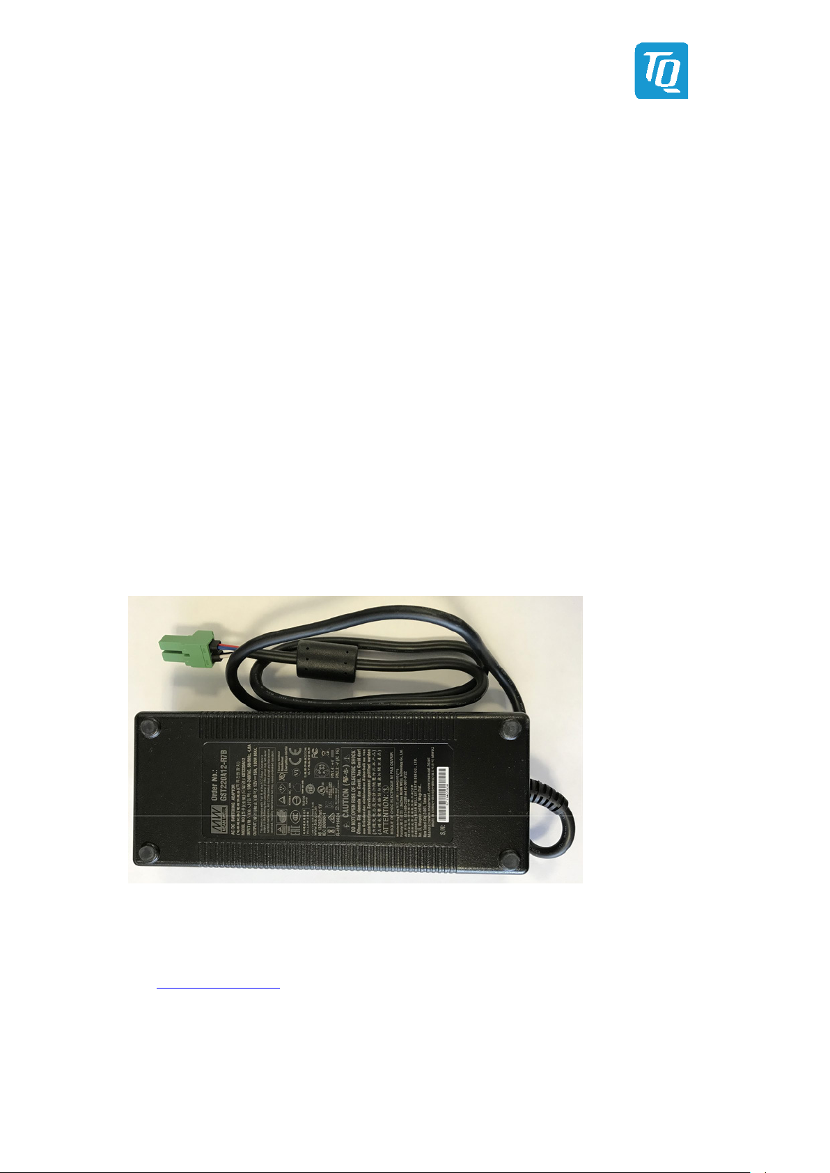
Meanwell 180W 12V Power Supply GST220A12-R7B
Please contact support@tq-group.com for details about Display Port cables and Display Port to DVI/HDMI adapters.

User's Manual l MB-COME6-4 UM 0100 l © 2022, TQ-Systems GmbH Page 6
3.
FUNCTION
3.1
Block Diagram
The following illustration shows the block diagram of the MB-COME6-4:
Figure 1: MB-COME6-4 Block Diagram
User's Manual l MB-COME6-4 UM 0100 l © 2022, TQ-Systems GmbH Page 7
3.2
Electrical Specification
3.2.1 Supply Voltage Characteristics
The MB-COME6-4 requires an input voltage of 12 V DC ±5 %.
The input voltages shall rise from 10 % of nominal to 90 % of nominal within 0.1 ms to 20 ms (0.1 ms ≤ Rise Time ≤ 20 ms).
There must be a smooth and continuous increase of each DC output voltage from 10 % to 90 % of its final set point within
the regulation range.
3.2.2 Power Consumption Specification
The power consumption of the system significantly depends on the connected devices; e.g. COM Express™ module, mass storage
devices, USB devices, display backlight, etc.
The power consumption of the MB-COME6-4 itself is approximately 2 W (COM Express™ module supplied externally);
UEFI-shell active; no keyboard, no mouse, no mass storage device, no Ethernet cable etc. connected).
Note: Power requirement
The MB-COME6-4 input current is not fused. The user has to ensure that the input current does not exceed the
maximum current of 25 A (300 W)
.
Additionally the power supply must be configured with enough reserve. It should be calculated with the
maximum power consumption of all connected components.
3.3
Environmental Specification
•Operating temperature, extended: –20 °C to +85 °C
•Storage temperature: –40 °C to +85 °C
•Relative humidity (operating / storage): 10 % to 90 % (not condensing)
3.4
System Components
3.4.1 Gigabit Ethernet Controller
The MB-COME6-4 provides an Intel®i225IT Ethernet controller with 10/100/1000/2500 Mbps speed (802.3 specification) and
IEEE1588 support.
Please contact support@tq-group.com for further information about the IEEE1588 support.
3.4.2 HD-Audio Controller
The MB-COME6-4 provides a Cirrus Logic CS4207 High Definition Audio Codec with a headphone output a line in input a
microphone input.

User's Manual l MB-COME6-4 UM 0100 l © 2022, TQ-Systems GmbH Page 8
3.5
Connectors and Interfaces
Figure 2: MB-COME6-4 Top view
X8/X9:
2 x 2.5 Gigabit
Ethernet
S2:
Power
Button
X10: Power In
12 V DC
S1:
Dip Switch for
LVDS/eDP or
ESPI/LPC
X3 / X4 / X5:
Display Port
X7:
2 × USB 3.0
X26: 12 V Fan
X18: SPI flash
socket
X22: SATA
socket
X1: COM Express™
connector (Row A/B)
Debug
LEDs
X23/X24: RS232
connector
X2: COM Express™
connector (Row C/D)
X12 (blue):
Line in
X13 (green):
Headphone out
X14 (pink): Mic in
S1:
Reset
Button
X20 / X21:
Debug socket
X19:
PCIe Card slot /
PEG port
X6:
USB Type C
X11:
SIM Card
socket for
WWAN cards
on M.2 B-Key

User's Manual l MB-COME6-4 UM 0100 l © 2022, TQ-Systems GmbH Page 9
Figure 3: MB-COME6-4 Bottom view
X45/X46/X47:
USB 2.0
X42:
M.2 socket
(E-Key)
X44:
M.2 socket
(M-Key for SSDs)
X40:
M.2 socket
(B-Key for
WWAN or SSD)
X38:
Embedded
DisplayPort
X27:
LVDS
X39:
Display Backlight
X43:
RTC battery
X41:
M.2 socket
(M-Key for SSDs)

User's Manual l MB-COME6-4 UM 0100 l © 2022, TQ-Systems GmbH Page 10
3.5.1 Power Supply
The MB-COME6-4 requires a single 12 V DC power supply. The supply voltage should not vary more than ±5 %.
X10: Power-In Connector
−Connector type: Phoenix PC4/2-G-7,62
−Mating connector: Phoenix PC4/2-ST-7,62 (up to 20 A)
Phoenix PC5/2-ST-7,62 (up to 25 A)
Table 2: Power-In Connector
Pin Signal Remark
1 12 V max. 25 A, current limit has to be supported from power supply
2 GND –
Note: Power requirement
The MB-COME6-4 input current is not fused. The user has to ensure that the input current does not exceed the
maximum current of 25 A (300 W)
.
Additionally the cable diameter has to be selected in correlation to the maximum current.
The mainboard power design is optimized for the new high performance TQMx110EB COM Express™ module.
This module can draw up to 200 W power for 10 seconds at power up.
3.5.2 DisplayPort
The MB-COME6-4 supports three DisplayPort interfaces.
Reference Naming Possible Resolution and Datarate
X3 DP2 8k (HBR3)
X4 DP3 8k (HBR3)
X5 DP1 4k (HBR2)

User's Manual l MB-COME6-4 UM 0100 l © 2022, TQ-Systems GmbH Page 11
3.5.3 USB Host Interfaces
The MB-COME6-4 supports several USB Host interfaces.
X7: USB 3.2 Gen 2 (up to 10 Gb/s) double Type A connector with USB 3.0 compatibility
Power: up to 1.5 A @ 5 V
X6: USB 3.2 Gen 2 (up to 10 Gb/s) Type C connector with USB 3.0 compatibility
Power: up to 3 A @ 5 V
X45 / X46 / X47: USB 2.0 host extension connector for usage of a USB 2.0 host port with an adapter cable
−Connector type: Molex 53398-0571
−Mating connector: Molex 51021-0500 crimp housing
Table 3: USB 2.0 Host Extension Connectors
Pin Signal Cable Colour
1 +5 V Red
2 D– White
3 D+ Green
4 GND Black
5 GND –
3.5.4 Gigabit Ethernet
The MB-COME6-4 supports two 2.5 Gigabit Ethernet ports.
The Ethernet signals of the COM Express™ connector are routed to the X8 (left) connector.
The MB-COME6-4 provides an Intel®i225 Ethernet controller with 10/100/1000/2500 Mbps speed, connected to the X9 (right)
connector.
Table 4: Ethernet LEDs
Figure 4: RJ45 Connectors
LED Status
Left, green (Link) Off: No link
Shines: Link established
Right, yellow (ACT) Off: No activity
Shines: Activity
Module Port
Carrier Port
(I225)

User's Manual l MB-COME6-4 UM 0100 l © 2022, TQ-Systems GmbH Page 12
3.5.5 Serial Interface (RS-232)
The MB-COME6-4 supports two RS232 serial ports at the on board connector
−Connector type: Molex 53398-1071
−Mating connector: Molex 51021-1000 crimp housing
The COM Express™ Specification does only provide signal definitions for RX and TX lines for the serial interface. Due to the TQ-
flexiCFG feature, the serial ports can be configured to route the handshake signals to free pins on the COM Express connector.
Table 5: Serial Port COM Express™ Port Mapping
COM Express Signal COM Express Pin MB-COME6-4 Remark
SER0_TX A98 SER0_TX 3.3 V input
SER0_RX A99 SER0_RX 3.3 V output
SER1_TX A101 SER1_TX 3.3 V input (not available)
SER1_RX A102 SER1_RX 3.3 V output (not available)
SER0_RTS# 1 B98 SER0_RTS# 3.3 V input
SER0_CTS# 1B99 SER0_CTS# 3.3 V output
SER1_RTS# 1D24 SER1_RTS# 3.3 V input (not available)
SER1_CTS# 1D25 SER1_CTS# 3.3 V output (not available)
The four COM Express™ serial signals (RX/TX) are specified to provide a protection and level shifter circuit.
The implementation of this circuit would result in a lower transfer speed on the two serial ports of the COM Express™ module.
On the MB-COME6-4 the protection circuit is removed and the serial ports provide a transfer rate of up to 115 kbaud.
The MB-COME6-4 can only be used in combination with Type 6 pinout COM Express™ modules.
Table 6: Serial Port RS-232 pinout via cable to 9-pin D-Sub
Figure 5: 10-pin RS232 Connector
1: These signals are not specified in COM Express™ specification.
These signals are only available when the TQ flexiCFG feature is available on the COM Express™ module. TQ modules support this feature.
2: Not available since signal is not defined in COM Express™ specification.
3: Only available when the TQ flexiCFG feature is available on the COM Express™ module.
Pin RS-232 Signal
(all signals) MB-COME6-4 D-Sub connector
(with DSUB-Adaptor)
1 DCD NC 2–
2 DSR NC 2RXD
3 RXD RXD TXD
4 RTS RTS 3–
5 TXD TXD 3 GND
6 CTS CTS –
7 DTR NC 2RTS
8 RI NC 2CTS
9 GND GND –
10 – NC –

User's Manual l MB-COME6-4 UM 0100 l © 2022, TQ-Systems GmbH Page 13
3.5.6 Embedded Display Port
The MB-COME6-4 provides an embedded DisplayPort (eDP where suitable displays can be directly connected.
To select the eDP interface on the MB-COME6-4 the DIP switch on the carrier has to be set to the “eDP” position.
This functionality is only available if the COM Express™ module provides the eDP interface.
Please contact support@tq-group.com for further information about eDP or LVDS support.
X38: eDP connector
−Connector type: JAE HD1S040HA1
−Mating connector: JAE HD1P040MA1
Table 7: eDP Connector
Figure 6: eDP Connector
Figure 7: Config Switch: eDP / LVDS
Pin Signal Remark
1 NC –
2 GND –
3 TX3– Lane 3 differential pair
4 TX3+
5 GND –
6 TX2– Lane 2 differential pair
7 TX2+
8 GND –
9 TX1– Lane 1 differential pair
10 TX1+
11 GND –
12 TX0– Lane 0 differential pair
13 TX0+
14 GND –
15 AUX+ AUX - channel
16 AUX–
17 GND –
18 3V3
3.3 V supply voltage
19
3V3
20 3V3
21 3V3
22
NC
–
23 GND
–
24 GND
25
GND
26 GND
27 HPD Hot Plug Detect
28 GND
–
29
GND
30 GND
31 GND
32 BLKT_EN Backlight enable
33 BLKT_CTRL Backlight (brightness) control
34 VDD_EN Panel power enable
35 AUX_SEL Low AUX; High I2C
36 V_BLKT
12 V Backlight supply voltage
37 V_BLKT
38
V_BLKT
39 V_BLKT
40 NC –

User's Manual l MB-COME6-4 UM 0100 l © 2022, TQ-Systems GmbH Page 14
3.5.7 LVDS
The MB-COME6-4 provides a LVDS interface where suitable displays can be directly connected.
To select the LVDS interface on the MB-COME6-4 the DIP switch on the carrier has to be set to the “LVDS” position.
This functionality is only available if the COM Express™ module provides the LVDS interface.
There are also connectors to power the backlight of the connected display.
The MB-COME6-4 has an on board EDID EEPROM to store display specific timing information. The EEPROM can be programmed
with an external I2C programmer. If the programmer supports 3.3 V output voltage, the MB-COME6-4 can be programmed
without any additional power supply. In this case no COM Express™ module should be connected to the carrier board.
X27: LVDS connector
−Connector type: Hirose DF19G-30P-1H
−Mating connector: Hirose DF19-30S-1C
Table 8: LVDS Connector
Figure 8: LVDS Connector
Pin Signal Remark
1 A0– Odd bus
2 A0+ Odd bus
3 A1– Odd bus
4 A1+ Odd bus
5 A2– Odd bus
6 A2+ Odd bus
7 GND –
8 ACLK– Odd bus
9 ACLK+ Odd bus
10 A3– Odd bus
11 A3+ Odd bus
12 B0– Even bus
13 B0+ Even bus
14 GND –
15 B1– Even bus
16 B1+ Even bus
17 GND –
18 B2– Even bus
19 B2+ Even bus
20 BCLK– Even bus
21 BCLK+ Even bus
22 B3– Even bus
23 B3+ Even bus
24 GND –
25 5V_PANEL
5 V Panel supply voltage26 5V_PANEL
27 5V_PANEL
28 3V3_PANEL
3.3 V Panel supply voltage
29 3V3_PANEL
30 3V3_PANEL

User's Manual l MB-COME6-4 UM 0100 l © 2022, TQ-Systems GmbH Page 15
X39: Backlight connector,
−Connector type: Molex 53398-1271
−Mating connector:Molex 51021-1200
Table 9: Backlight Connector
Figure 9: Backlight Connector
4: The EEPROM can be powered by the 3V3_PROG pin.
5: These pins can be used to program the on-board EDID EEPROM.
3.5.8 M.2 socket with M Key (for PCIe SSD devices)
The MB-COME6-4 provides one socket to support PCIe based M.2 SSD with 22 mm width and 80 mm length.
A PCIe ×4 interface is routed to this socket.
M.2 2280 single and double sided modules with M key (PCIe only) can be inserted.
The transfer rate of this interface mainly depends on the COM Express™ module and the connected device.
Please contact support@tq-group.com for further information about suitable M.2 SSDs.
3.5.9 M.2 socket with M Key (for PCIe SSD devices)
The MB-COME6-4 provides one socket to support PCIe based M.2 SSD with 22 mm width and 42 mm length.
A PCIe ×2 interface is routed to this socket.
M.2 2242 single and double sided modules with M key (PCIe only) can be inserted.
The transfer rate of this interface mainly depends on the COM Express™ module and the connected device.
Please contact support@tq-group.com for further information about suitable M.2 SSDs.
3.5.10 M.2 socket with B Key (for WWAN modules or SATA SSD devices)
The MB-COME6-4 provides a socket to support SATA based M.2 SSDs with 22 mm width and 80 mm length or modules with 22
mm width and 42 mm length.
1x USB 2.0 and SATA signals are routed to this socket.
For mounting the short module a distance cap from Würth 9779807025 is needed.
M.2 2280 / 2242 / 3042 single and double sided modules with B Key (SATA and USB 2.0 only) can be inserted.
The reachable transfer rate of this interface depends mainly on the module used and the connected device.
3.5.11 M.2 socket with E Key (for I/O devices)
The MB-COME6-4 provides a socket for an M.2 module with 22 mm width and 30 mm length.
1x USB 2.0 and PCIe ×1 signals are routed to this socket.
M.2 2230 single and double sided modules with E or A+E key can be inserted.
The transfer rate of this interface mainly depends on the COM Express™ module and the connected device.
Pin Signal Remark
1
VCC_BKLT_OUT Backlight voltage output
2
3
4
GND –
5
6
7 NC –
8 LCD0_BKLT_EN Display 0 Backlight Enable output
9 LCD0_BKLT_CTRL Display 0 Backlight (brightness) control
10 3V3_PROG 43.3 V input (programming)
11 EDID_CLK 5EDID I2C clock
12 EDID_DAT 5EDID I2C data

User's Manual l MB-COME6-4 UM 0100 l © 2022, TQ-Systems GmbH Page 16
3.5.12 SATA Interfaces
The MB-COME6-4 supports to two SATA interfaces:
•M.2 socket for M.2 B Key SSDs modules
•one standard 7-pin SATA connector
The transfer rates of these interfaces mainly depend on the COM Express™ module and the connected devices.
3.5.13 Audio
The MB-COME6-4 provides an audio codec to support following audio features:
•Microphone in (pink) 1
•Headphone out (green)
•Line in (blue)
Figure 10: Audio Connectors X12, X13, X14
3.5.14 Fan Connector
The MB-COME6-4 provides a connector for 12 V fans.
X26: 12 V fan connector
−Connector type: Tyco 640456-3
−Mating connector: 3-pin fan connector (2.54 mm pitch)
Table 10: Fan Connector
Figure 11: Fan Connector
3.5.15 PCI Express Connector
The MB-COME6-4 provides a standard PCI Express x16 slot connector.
The PCI Express port can be used for PCI Express graphics devices or high speed non-graphic PCI Express devices
(e.g. quad Gigabit Ethernet or 10/40/100 Gigabit Ethernet controller).
X19: Standard x16 PCI Express connector
The reachable transfer rate of this interface depends mainly on the COM Express module used and the connected device.
1Only microphones with external bias supply can be used.
Pin Signal Remark
1 GND –
2 Fan Voltage Output voltage (0 to 12 V PWM)
3 SENSE Sense input for fan speed

User's Manual l MB-COME6-4 UM 0100 l © 2022, TQ-Systems GmbH Page 17
3.5.16 Feature Connector
The MB-COME6-4 provides two pin header, where few COM Express™ signals are available.
This connector is for debug and software development purposes. The user can access to SMBus, I2C bus and a few other signals.
−Connector type: Male Pin header with 2-rows and 2,54 mm pitch
−Mating connector: Female Pin header with 2-rows and 2,54 mm pitch
Table 11: GPIO and COME Signal Connector X20
Figure 12: Feature Connectors
Table 12: I2C and COME Signal Connector X21
Pin Signal Remark
1 V_3V3_STBY 3.3 V supply
2 GND -
3 V_3V3_STBY 3.3 V supply
4 GND -
5 GPI0 Input
6 GPO0 Output
7 GPI1 Input
8
GPO1
Output
9 GPI2 Input
10 GPO2 Output
11 GPI3 Input
12 GPO3 Output
13 SMB_CK SM bus clock
14 SUS_S3# Suspend to RAM
15 SMB_DAT SM bus data
16
SUS_S4#
Suspend to disk
17
SMB_ALERT#
SM bus alert
18 SUS_S5# Soft off
19 BATLOW# Battery low signal
20 COME_WDT Come Watchdog Timer
Pin Signal Remark
1 V_5V_STBY 5 V supply
2 GND -
3 V_5V_STBY 5 V supply
4 GND -
5 PWR_BTN# Power Button
6 GND -
7 RST_BTN# Power Button
8 GND -
9 I2C_CK COM Express™ I2C bus clock
10 BIOS_DIS0# COM Express™ Boot from carrier SPI
socket.
11 I2C_CK COM Express™ I2C bus clock
12 Wake1# COM Express™ wake up signal
13 THRMTRIP# Thermal shutdown signal from module
14 LID# COM Express™ LID switch
15 SLEEP# Sleep button signal to module
16 THRM# COM Express™ input from off-Module
temp sensor
17 SATA_ACT# COM Express™ Serial ATA (activity
indicator)
18 RAPID_SHUTDOWN
COM Express™ trigger for Rapid
Shutdown
19 - -
20 - -
Table of contents
Other TQ Carrier Board manuals


