Specac GS03940 User manual

Mini-Pellet Press
User Manual
2I-03940-6


Mini-Pellet Press
User Manual
2I-03940-6

User Manual
2
Mini-Pellet Press P/N GS03940
CONTENTS
1. INTRODUCTION ................................................................................. 3
2. CHECKLIST OF CONTENTS ................................................................. 4
3. OPERATION OF THE MINI-PELLET PRESS ........................................... 5
PREPARATION OF THE 7MM PELLET DIE ASSEMBLY ............................ 6
PRESSING THE 7MM PELLET DIE IN THE MINI-PELLET PRESS .............. 8
REMOVING THE 7MM PELLET DIE ASSEMBLY FROM THE MINI-PELLET
PRESS ........................................................................................... 10
POSITIONING THE KBR PELLET DIE RING HOLDER IN THE
SPECTROMETER ............................................................................. 11
CLEANING OF PELLET DIE PARTS AND KBR PELLET REMOVAL INTACT
FROM THE PELLET RING HOLDER ................................................... 12
4. SPARE PARTS FOR THE MINI-PELLET PRESS .................................... 14
5. LEGEND FOR THE MINI-PELLET PRESS ............................................. 15
© April 2016 Specac Ltd. All rights reserved.
Brilliant Spectroscopy™ is a trademark of Specac Ltd.
Other product names mentioned herein may be trademarks
of their respective owners.

Mini-Pellet Press
3
1. Introduction
Thank you for buying a product from Specac.
The Specac Mini-Pellet Press P/N GS03940 has been designed to
produce a maximum 2 tons load and when used with the 7mm Pellet
Die assembly P/N GS03950, provides a sufficient load for the
formation of excellent quality KBr pellets with a 7mm diameter, prior to
solid sample analysis by FTIR spectroscopy. The Mini-Pellet press and
7mm Pellet Die assembly items are an alternative to the use of,
typically, a 13mm diameter pellet die assembly within a 15 ton manual
hydraulic press to produce 13mm diameter KBr pellets/discs.
When the 7mm pellet die assembly with a KBr sample has been
placed in the Mini-Pellet Press, a 2 tons load can be easily and quickly
applied by turning of a pressure screw hand knob. This action
compresses a hydraulic fluid (oil) to raise a pressing piston and
compress a sample held in the pressing area. To assist in the turning
of the pressure screw knob an M8 (6mm A/F) size short handled Allen
key is included to fit the central socket screw for greater leverage if
required. To help in knowledge of the load being applied there is a
small pressure indicator gauge on the press body which shows the
actual pressure being applied and when to stop turning the hand knob.
The Mini-Pellet Press is small and relatively light enough in weight that
it could be held in the hand to turn the pressure screw knob if desired,
but for more secure use the press has been designed to sit and work
on a bench surface.
Warning: If you use the Mini-Pellet Press near the edge of a bench
surface to turn the pressure screw knob, be careful that as
much of the weight of the press as possible is on the bench
surface itself, to prevent the press from falling to the floor.
There is no requirement to permanently bolt the press to a work
surface to apply a load safely to a sample, thus enabling easy storage
of the press if needed.

User Manual
4
2. Checklist of Contents
Check that the following items have been supplied against P/N
GS03940:
Mini-Pellet Press
- P/N GS03940.
If a 7mm Pellet Die assembly P/N GS03950 has been ordered too
check that the following items have been included.
7mm Pellet Die assembly P/N GS03950
(including its own Pellet Ring Holder, Top
Anvil, Bottom Anvil and Perspex Extractor
Cap).
M8 Allen key for leadscrew and pressure knob handles.
Unpack the Mini-Pellet Press and die parts carefully (if ordered) and
prepare the items for use.
Mini-Pellet Press
5
3. Operation of the Mini-Pellet Press
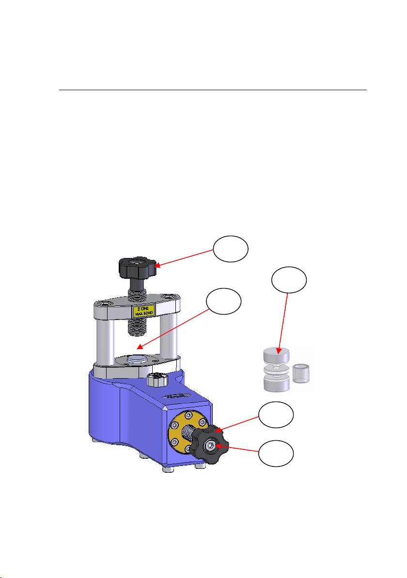
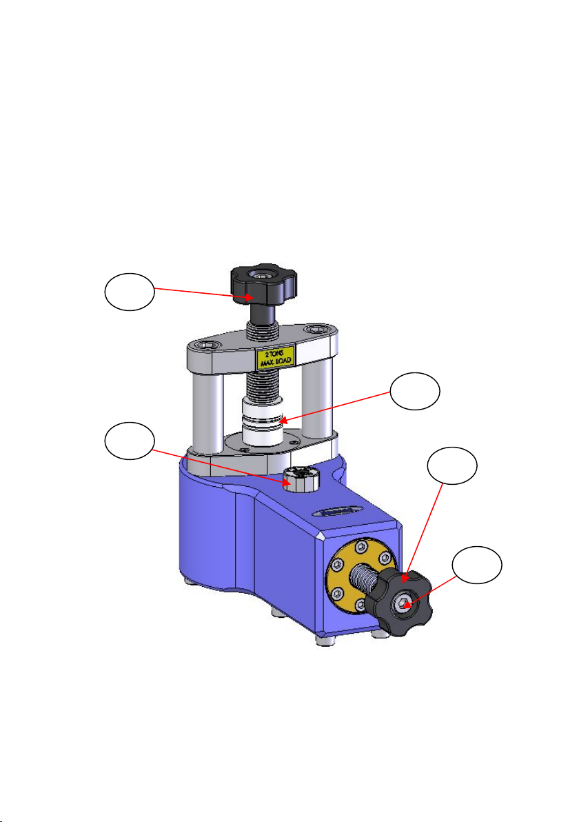
Pressing a sample in the Mini-Pellet Press is simple and quick. Taking
the 7mm pellet die assembly (P/N GS03950) (1) as an example die to
use, it is easily located within the pressing area of the Mini-Pellet Press
(2). The lead screw assembly (3) is turned until hand tight to secure
the 7mm pellet die assembly (1) in position in readiness to turn the
pressure screw hand knob assembly (4). Only a light force is needed
to turn the pressure hand knob (4) to provide a sufficient tonnage load,
but the M8 Allen key provided can be used to turn the central socket
screw (5) for greater leverage if desired. The produced 7mm KBr pellet
is retained within the pellet die ring holder body (6) and this is
transferred to a 3” x 2” slide mount (7) to fit in the spectrometer. (See
Fig 1.)
Fig 1. Mini-Pellet Press and 7mm Pellet Die Assembly
1
2
3
4
5
User Manual
6
Preparation of the 7mm Pellet Die Assembly
Prior to placing the 7mm pellet die assembly (1) into the Mini-Pellet
Press pressing area (2), a potassium bromide (KBr) powder mixture
with a solid sample is prepared. A suitable quantity of the solid sample
with an amount of KBr powder (P/N GS03610) in the usual ratio of 1
part sample to 300 parts KBr can be ground together using the agate
pestle and mortar (P/N GS03600) or an automatic grinding mill such as
the Specamill (P/N GS06000) with an agate capsule set (P/N
GS06200).
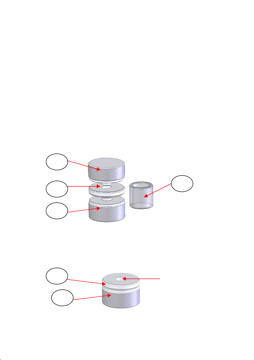
The 7mm pellet die assembly complete (1) consists of a central pellet
ring holder (6), top anvil (8), a bottom anvil (9) and a clear Perspex
extractor ring cap (10). (See Fig 2.) The top anvil (8) has a longer
central “plunger” section than the bottom anvil (9).
Fig 2. 7mm Pellet Die Assembly Complete
When the sample has been ground sufficiently, place some of the KBr
mixture into the central hole of the 7mm pellet die ring holder (6) as it
rests on the bottom anvil (9). (see Fig 3.)
Fig 3. 7mm Pellet Die Ring Holder (Body) on Bottom Anvil
10
8
6
9
6
9
KBr powder sample
mixture placed here
Mini-Pellet Press
7
Fill the aperture hole of the 7mm pellet die ring holder (6) with sufficient
KBr powder mixture to reach the top. Using a flat blade or the edge of
the spatula, level off the powder mixture such the top of the powder
mixture in the hole is flush with the 7mm pellet die ring holder’s (6) top
surface.
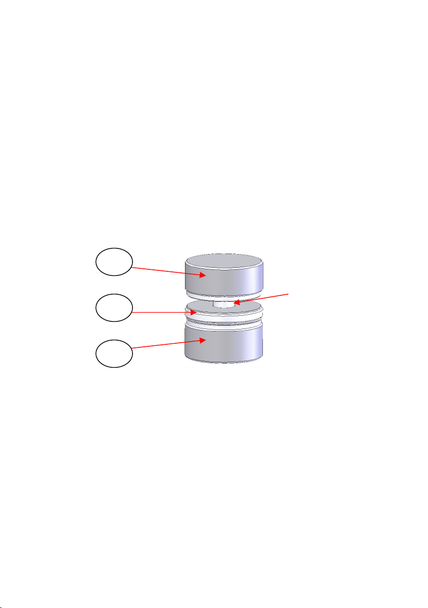
Now, take the top anvil (8) and place it carefully (plunger face
downwards) over the powder/7mm pellet die ring holder (6)/bottom
anvil (9) assembly. Locate the central plunger section of the top anvil
(8) over the powder sample within the aperture hole and use light
pressure from your hand to compact the powder mixture into the hole.
The mixture is sufficiently soft to allow the plunger part of the top anvil
(8) to fit and locate loosely into place in the aperture hole of the 7mm
pellet die ring holder (6).. (See Fig 4.)
Fig 4. 7mm Pellet Die Assembly with Sample Prior to Pressing
When this stage has been reached you can carefully transfer this
complete 7mm pellet die assembly (with sample) into the Mini-Pellet
Press for full pressing of the KBr powder sample.
Note: The bottom anvil (9) has a recessed underside surface with a
metal rim around its circumference. The recess allows for central
and correct positioning of the 7mm pellet die assembly (1) over
the piston (11) of the Mini-Pellet Press prior to any pressing.
8
6
9
KBr powder mixture is
now partially compacted
within this assembly
User Manual
8
Pressing the 7mm Pellet Die in the Mini-Pellet Press
Prepare the Mini Pellet Press to accept the 7mm pellet assembly (1) as
formed at the stage shown to Fig 4.
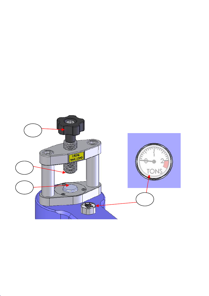
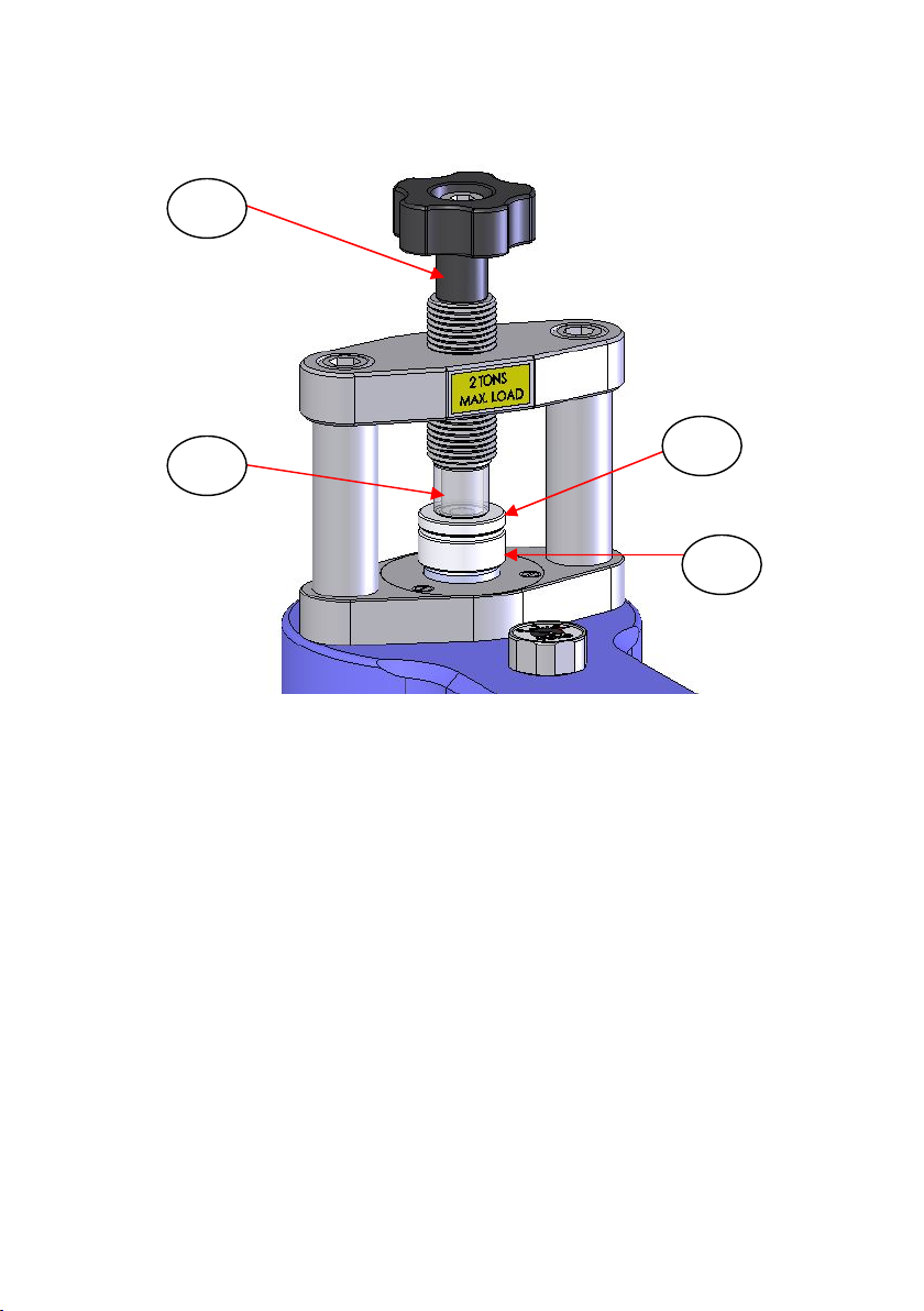
The lead screw (3) on the Mini-Pellet Press is retracted (turned
anticlockwise) so there is sufficient “daylight” between the pressing
face of the leadscrew (12) and the piston (11) of the Mini-Pellet Press.
The piston (11) will be at its rest position for the start of its travel. This
will be when there is no applied pressure on the system from the
pressure hand knob (4) or shown at the pressure/load gauge (13).
(See Fig 5.)
Fig 5. Mini-Pellet Press Piston Area and Pressure Gauge Reading
Before Applying a Load
Before applying any pressure (load), to the die assembly (1) when it is
placed into the press, the pressure screw hand knob assembly (4)
13
3
12
11
Mini-Pellet Press
9
should be fully unwound to its start position. Turn the pressure knob (4)
anticlockwise until it will turn no further such that the screw assembly
has reached its end stop. When the pressure screw hand knob
assembly (4) is fully retracted, the pressing piston (11) will be at its
correct start position for pressing.
When the Mini-Pellet Press pressing area has been set to accept the
7mm pellet die assembly (1), place the die assembly carefully and
centrally into the press and loosely clamp the die assembly into
position by turning the lead screw assembly (3) clockwise. (See Fig 6.)
Fig 6. Mini-Pellet Press with 7mm Die Assembly in Position
3
1
4
13
5
User Manual
10
Before turning the pressure screw knob assembly (4) to apply a load,
tighten the lead screw handle assembly (3) a little further clockwise to
continue the initial compaction of the KBr powder mixture contained
within the die. When the lead screw (3) can no longer be hand
tightened, the KBr powder mixture is ready to be fully compressed by
application of a load provided by turning of the pressure knob screw
assembly (4). Begin applying a load by turning the pressure knob (4)
clockwise. It will be easy to turn at the start, but gets progressively
harder to turn as the pressure (a tonnage load) increases and is being
applied to the die assembly (1). (Use the M8 Allen Key supplied if
required in screw (5).) The increase in pressure will be indicated by the
pressure gauge (13) on the Mini-Pellet Press body.
Continue turning the pressure knob (4) until the pressure gauge (13)
needle is pointing at the 1.75 tons division indicator. At this tonnage
reading stop turning the pressure screw knob assembly (4). This will
be a sufficient tonnage load to have compacted the KBr powder
together to form a suitable pellet.
Note: On the pressure gauge (13) there is a red colour warning area
beyond the maximum 2 ton load reading. NEVER over-
pressurise the Mini-Pellet Press such that the indicator needle
has entered this red colour section of the pressure gauge.
Removing the 7mm Pellet Die Assembly from the Mini-
Pellet Press
When the 7mm pellet die assembly (1) has been compressed to a
sufficient tonnage load to form a solid KBr pellet within the pellet die
ring holder (6), the die assembly (1) can be removed from the Mini-
Pellet Press.
Remove the pressure (tonnage load) from the pellet die assembly (1)
by anticlockwise rotation of the pressure knob screw assembly (4).
When the pressure gauge (13) indicator needle drops to zero tons the
7mm pellet die assembly (1) should be free to be removed from the
pressing area (2). However, it is always best to fully retract the
pressure screw knob assembly (4) to its end stop, to ensure that the
piston (11) returns to its correct start/rest position for a new pressing.
Mini-Pellet Press
11
Positioning the KBr Pellet Die Ring Holder in the
Spectrometer
Having removed the compressed 7mm pellet die assembly (1) from the
Mini-Pellet Press, the top anvil (8) and bottom anvil (9) are
separated/removed from the die ring holder (6). Hold the knurled outer
edge of the die ring holder (6) with one hand and twist/turn the anvils
(8 and 9) by holding their knurled edges with the other hand. The
KBr/sample powder material will have been compacted into a 7mm
diameter pellet contained in the die ring holder (6) central aperture
hole.
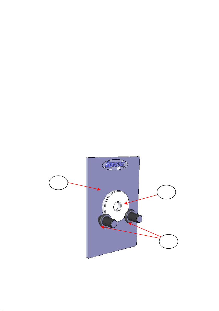
The complete die ring holder (6) with KBr pellet is now placed into an
infra red spectrometer system by use of the 3” x 2” slide mount holder
(P/N GS03960) (6). The die ring holder (6) rests simply on the two
support rods of the 3” x 2” slide mount holder (7) and is held tight
against the 3” x 2” slide plate by compression of the two O-rings (14)
supplied having been slid over the support rods as shown. (See Fig 7.)
Fig 7. 7mm Pellet Die Ring Holder on 3” x 2” Slide Mount
7
6
14

User Manual
12
Cleaning of Pellet Die Parts and KBr Pellet Removal
Intact from the Pellet Ring Holder
When the KBr pellet sample being held in the die ring holder (6) has
been analysed, the KBr sample must be removed from the die ring
holder (6) for pressing of a new sample into the same die ring holder.
To remove the KBr pellet, the entire KBr pellet and die ring holder (6)
assembly can be rinsed with cold or warm water to gradually dissolve
the KBr sample. When the KBr sample has been washed away from
inside the holder, the die ring holder (6) part can be further
washed/rinsed with methanol and then dried with tissues. Specac
would also then recommend that this part could be stored in dry
environment or placed on a heated surface (circa 30°C to 35°C) prior
to use for the next time.
After initial pressing of the pellet into the die ring holder (6) (from
sample preparation stage), the top anvil (8) and bottom anvil (9) should
also be rinsed with water, then methanol, dried with tissues and stored
on a heated top plate surface ready for next use.
However, if you would wish to save the 7mm KBr pellet that has been
formed within the die ring holder (6) after it spectroscopic analysis,
then this KBr pellet can be removed intact from the die ring holder (6)
part, by use of the top anvil (8) with the longer plunger and the Perspex
die extractor cap piece (10).
Take the die ring holder (6) with KBr pellet and place the plunger of the
top anvil (8) into the aperture hole on one side of the die ring holder
(6). Place this combined assembly with the Perspex extractor cap (10)
in contact with other side of the die ring holder (6) into the Mini-Pellet
Press pressing area (2) as shown in Fig 8. Make sure that this
assembly of parts is placed centrally between the lead screw pressing
face (12) and the piston surface (11).
Mini-Pellet Press
13
Fig 8. 7mm Pellet Die Ring Holder, Top Anvil and Extractor Cap
Assembly in Position for KBr Pellet Extraction
Loosely hold the components together by turning the lead screw
assembly (3) clockwise and then continue turning the lead screw
assembly (3) to allow the top anvil (8) to push the KBr pellet out of the
die ring holder (6) and into the space created by the Perspex extractor
cap (10).When the KBr pellet has been pushed out of the die ring
holder (6), retract the lead screw assembly (3) by a couple of
anticlockwise turns and carefully remove the assembly of parts from
the Mini-Pellet Press pressing area (2) to gain access to the KBr pellet.
The intact KBr pellet can now be saved or used for any further purpose
and the die ring holder (6) and top anvil (8) parts can be cleaned
(water and then methanol rinses, then drying and placed on a hot
surface) as described previously, ready to be used again for the next
KBr sample pressing.
3
10 6
8

User Manual
14
4. Spare Parts for the Mini-Pellet Press
P/N GS03940 – Mini-Pellet Press.
P/N GS03950 - 7mm Pellet die assembly complete.
P/N GS03951 - 7mm Pellet die ring holder (body).
P/N GS03952 - 7mm Pellet die top anvil (long plunger).
P/N GS03953 - 7mm Pellet die bottom anvil (short plunger).
P/N GS03954 - 7mm Pellet die Perspex extractor cap.
P/N GS03600 - Pestle and Mortar.
P/N GS03610 - KBr powder (50g).
P/N GS03960 - 3” x 2” slide mount for 7mm pellet die ring holder.

Mini-Pellet Press
15
5. Legend for the Mini-Pellet Press
(1) 7mm Pellet die assembly.
(2) Pressing area of Mini-Pellet Press.
(3) Lead screw assembly.
(4) Pressure screw knob assembly.
(5) Pressure screw knob assembly.
(6) Pellet die ring holder (body).
(7) 3” x 2” slide mount.
(8) Top anvil (long plunger).
(9) Bottom anvil (short plunger).
(10) Perspex extractor cap.
(11) Lead screw pressing face.
(12) Piston.
(13) Pressure gauge.
(14) O-rings for ring holder fixing when fitted on 3” x 2” slide mount.
Specifications of the Mini-Pellet Press
Maximum load - 2 tons.
Pellet Die diameter 7mm.
Maximum space between pressing faces - 45mm.
Minimum space between pressing faces - 15mm.
Piston stroke - 0.5mm.
Upper pressing face area (lead screw diameter) - 17.0mm.
Lower pressing face area (piston diameter) - 21.6mm.
Dimensions (excluding leadscrew assemblies) - 110mm wide x 200mm
long x 155mm high.
Dimensions (including leadscrew assemblies) - 110mm wide x 265mm
long x 215mm high.
Weight - 4.2Kg.

User Manual
16
Blank Page - Notes for Use of Mini-Pellet Press

Worldwide Distribution
France
Eurolabo - Paris.
Tel.01 42 08 01 28
Fax 01 42 08 13 65
email: contact@eurolabo.fr
Germany
L.O.T. - Oriel GmbH & Co,
KG - Darmstadt
Tel: 06151 88060
Fax: 06151 880689
email:info@LOT-Oriel.de
Website: www.LOT-Oriel.com/de
Japan
Systems Engineering Inc. -Tokyo
Tel: 03 3946 4993
Fax: 03 3946 4983
email:systems-eng@systems-eng.co.jp
Website: www.systems-eng.co.jp
Spain
Teknokroma S.Coop C. Ltda
Barcelona
Tel: 93 674 8800
Fax: 93 675 2405
email: comercial@teknokroma.es
Switzerland
Portmann InstrumentsAG
Biel-Benken
Tel: 061 726 6555
Fax: 061 726 6550
email: info@portmann-instruments.ch
Website:www.portmann-instruments.ch
USA
SPECAC INC.
414 Commerce Drive
Suite 175,
Fort Washington,
PA 19034, USA
Tel: 215 793 4044
Fax: 215 793 4011
United Kingdom
Specac Ltd. - London
Unit 12, Science & Innovation Centre
Halo Business Park
Orpington
Kent BR5 3FQ
Tel:+44 (0) 1689 873134
Registered No. 1008689 England

Brilliant Spectroscopy™
www.specac.com
SPECAC INC.
414 Commerce Drive
Suite 175,
Fort Washington,
PA 19034, USA
Tel: 215 793 4044
Fax: 215 793 4011
SPECAC LTD.
Unit 12, Science & Innovation Centre
Halo Business Park
Orpington
Kent BR5 3FQ
Tel: +44 (0) 1689 873134
Registered No. 1008689 England
Other Specac Power Tools manuals

Specac
Specac Atlas Power 8Ton User manual

Specac
Specac Atlas Autotouch 40T User manual

Specac
Specac Atlas GS15800 User manual

Specac
Specac Apex 400 User manual

Specac
Specac Atlas 15T User manual

Specac
Specac Atlas Power 8Ton User manual

Specac
Specac Apex 400 Press User manual

Specac
Specac Atlas Lightweight Evacuable Pellet Die User manual

Specac
Specac Atlas Automatic 40 Ton User manual


