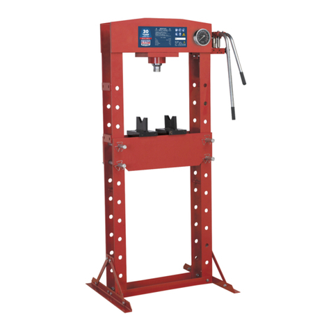
Specac Atlas Autotouch 40T User manual

Atlas™ Autotouch 40Ton (40T)
Hydraulic Presses
User Manual
2I-25830-3


Atlas™ Autotouch 40Ton (40T)
Hydraulic Presses
User Manual
2I-25830-3

User Manual
2
Specac manufactures and stocks a full range of IR sampling
accessories for solids, liquids and gases and optical components.
We design and manufacture full integrated sampling solutions for
the laborator , at line and in-line process measurement, to cope
with extremes of temperature from –190ºC to +800ºC, pressures
from vacuum to 5000psi and corrosive conditions.
♦ Single and multiple reflection ATR systems
Golden Gate ATR (-150ºC to +300ºC)
Quest ATR
Gatewa ATR (up to +200ºC)
25 Reflection ATR
♦ Transmission – Fixed/Variable pathlength gas cells up to 0m
C clone (up to +200ºC)
Tornado
Storm (up to +250ºC)
♦ Diffuse Reflectance
Selector
Minidiff Plus
♦ Specular Reflectance
Monola er
Fixed Angle
♦ Transmission – Liquids and Solids
Omni-Cell
Pearl
Liquid Flow Cells
Variable Temperature Cell Holder (-190ºC to +250ºC)
Heating Jacket (up to +250ºC)
♦ Extreme Conditions
Environmental Chamber (up to +800ºC, 500psi)
High Temperature High Pressure Cell (up to +800ºC, 1000psi)
♦ Sample Preparation
Presses and Dies (up to 40 tons)
Film Maker (up to +400ºC)
♦ Polarizers
www.specac.com

Atlas™ Autotouch 40T Hydraulic Presses
3
Atlas™ Autotouch 40Ton (40T) Hydraulic
Presses P/N GS2 830 Series
CONTENTS
1
I
NTRODUCTION
................................................................................. 5
2.
U
NPACKING
C
HECKING
A
ND
I
NSTALLATION
....................................... 7
3.
G
ENERAL SAFETY
........................................................................... 11
4.
D
IAGRAMS
O
F
T
HE
A
TLAS
™
A
UTOTOUCH
40T
P
RESS
..................... 15
5.
O
PERATION
O
F
T
HE
A
TLAS
™
AUTOTOUCH
40T
P
RESS
.................... 18
G
ENERAL
P
ROCEDURE
................................................................... 18
D
ISPLAY
S
CREENS
......................................................................... 19
F
UNCTION
B
UTTONS
....................................................................... 19
O
PERATION
S
YMBOLS
.................................................................... 20
O
PERATION
S
TEPS TO
P
RESS A
S
AMPLE
......................................... 24
C
HANGING
L
ANGUAGE
D
ISPLAY AND
U
NITS OF
L
OAD
....................... 26
P
LACING
W
ORK IN THE
A
TLAS
™
A
UTOTOUCH
40T
P
RESS
............... 26
A
PPLYING A
L
OAD WITH THE
A
TLAS
™
A
UTOTOUCH
P
RESS
.............. 27
R
ELEASE OF THE
A
PPLIED
L
OAD
..................................................... 31
O
PERATION
-
F
URTHER
F
EATURES OF THE
P
RESS
.......................... 35
T
HE
S
AFETY
G
UARDS
..................................................................... 35
T
HE
P
RESSING
A
REA
...................................................................... 36
P
ISTON
T
RAVEL
............................................................................. 38
T
WO
-S
TAGE
P
RESSING
P
ROCESS FOR
H
IGHLY
C
OMPRESSIBLE
S
AMPLES
....................................................................................... 39
U
SE OF THE
S
TOP
B
UTTON
............................................................. 40
6.
D
ISPLAY
S
CREENS
-
O
PERATION
,
O
PTIONS
,
P
ROGRAMMING
,
D
IRECTORY AND
E
DITING
................................................................ 42
1)
M
AIN
O
PERATION
S
CREEN
(MOS) .............................................. 42
2)
O
PTIONS
S
CREEN
(O
PT
) ............................................................ 49
3)
P
ROGRAMMING
S
CREEN
(P
GM
) .................................................. 51
4)
D
IRECTORY
S
CREEN
(D
IR
) ......................................................... 54
5)
E
DITING
S
CREEN
(E
DIT
)............................................................. 56

User Manual
4
7.
N
ON
-R
OUTINE
P
ROCEDURES
F
OR
T
HE
A
TLAS
™
A
UTOTOUCH
40T
P
RESS
.................................................................................... 67
A
BORTING A
P
RESSING
P
ROCEDURE
.............................................. 67
W
ORK
B
ECOMES
"T
RAPPED
"
IN THE
P
RESSING
A
REA
....................... 67
N
O
S
AMPLE IN THE
P
RESSING
A
REA
................................................ 68
8.
F
AULT
F
INDING
,
C
AUSES AND
R
EMEDY FOR
A
TLAS
™
A
UTOTOUCH
40T
P
RESSES
............................................................................... 69
9.
G
ENERAL
P
REVENTATIVE
M
AINTENANCE OF
A
TLAS
™
A
UTOTOUCH
P
RESSES
....................................................................................... 74
C
HECKING THE
O
IL
L
EVEL AND
C
HANGING THE
O
IL
.......................... 74
C
HECKING OF
P
RESS
P
ERFORMANCE
.............................................. 75
L
EAD
S
CREW
A
SSEMBLY
L
UBRICATION
............................................ 76
10.
A
UTOMATIC
C
ONTROL
O
F THE
A
TLAS
™
AUTOTOUCH
40T
P
RESS
B
Y
USB
C
ONNECTIVITY
................................................................ 77
11.
A
CCESSORIES FOR
A
TLAS
™
A
UTOTOUCH
P
RESSES
....................... 77
12.
S
PECIFICATIONS OF
A
TLAS
™
A
UTOTOUCH
P
RESSES
..................... 78
13.
EC
D
ECLARTION OF
C
ONFORMITY
................................................. 79
© November 2016 Specac Ltd. All rights reserved.
Brilliant Spectroscop is a trademark of Specac Ltd.
Other product names mentioned herein ma be
trademarks of their respective owners.

Atlas™ Autotouch 40T Hydraulic Presses
5
1. Introduction
Thank ou for purchasing a Specac product.
The Atlas™ Autotouch 40Ton (40T) H draulic Presses are automatic
and programmable h draulic presses which have been designed for a
wide variet of pressing applications within the laborator or heav
industrial environments, to appl a load at a minimum of 4 tons up to a
maximum of 40 tons. These presses are specificall suited to the
preparation of solid sample discs, particularl for pellets at 40mm
diameter using Specac Atlas™ evacuable pellet die assemblies, from
the higher tonnage loads offered b the pressing s stem that ma be
needed to appl across larger surface areas of a sample for
compaction.
The Atlas™ Autotouch 40T presses enable the controlled application
and release of an applied load via push button or programmable timed
functionalit and can accommodate large samples up to 240mm wide,
220mm deep and 155mm tall. The operations to set a specific load to
appl or create a program for a load application sequence for its
duration of hold are carried out via a touch sensitive displa screen.
There are two ph sical buttons on the front panel to push for actual
operation of the press – a start button to appl a load and a stop button
to release the load.
The press works b automatic motorised pumping of a h draulic fluid
(oil) to raise a piston and compress a sample held in the pressing area.
The press consists of a motor, pump and oil reservoir assembl from
where the oil is transferred across to the base of the pressing area and
forced under the piston assembl . As the oil pressure builds up in the
press s stem the load being applied to the sample will be registered on
the electronic displa . The application of a load will continue until the
required load is reached and then held until released b the operator.
Alternativel , the load can be applied in a series of load stages via a
specific program and automaticall released from a programmed time
hold function and controlled release rate. The power unit is extremel
quiet and operates below 62 dB(A) making the presses ideal for use in
all environments.

User Manual
6
The sample is held in the pressing area prior to compression b use of
a lead screw and top anvil pressing face mechanism. Incorporated into
this mechanism are compression disc springs that allow for a slow
release of an load to the sample pressing procedure. In the
compression process the disc springs will be initiall compressed
before full resistance is met to stop the travel of the piston. When an
stored load is released the disc springs will relax to their non-
compressed state and hence provide for a slow release of a full load.
An important part of the press is the safet guard mechanism. For an
operation of the press the safet guard must be in its closed (down)
position. Accidental raising of the guard, even if the press is under
load, will automaticall abort the pressing operation and reduce the
load from the s stem to render it safe. Please read section 3 on
pages 11 to 14 regarding safe operation before using the press
for the first time.
The Atlas™ Autotouch 40T press is provided with USB connectivit if it
is a requirement to operate the press remotel from a computer
s stem. For remote operation, please see Section 10 in this manual.
The Atlas™ Autotouch 40T press is full CE marked to compl with
strict European regulations.
WEEE Directive For Equipment Disposal
The s mbol (above) on the back of the press indicates that this product
complies with the Waste Electrical and Electronic Equipment Directive
(WEEE). If this product is in use and was purchased within the
European Union, please contact our local sales agent or Specac to
make arrangements for disposal of this equipment.

Atlas™ Autotouch 40T Hydraulic Presses
7
2. Unpacking, Checking and Installation
Beware! The Atlas™ Autotouch 40T press is very heavy and care
must be taken to transport it correctly. lease keep the
press packing materials for future transportation by
reversing the following procedure. This will protect you
and the press from accident or injury.
The Atlas™ Autotouch 40T press is shipped in a timber packing case
with a special pallet base. The press is packed with a lifting “e e bolt”
assembl alread fitted, read for lifting with the customer’s crane.
Having alread removed the screws around the top perimeter of the
timber packing case and lifted off the top lid to allow access to the
instruction manual (as advised from the external warning label on the
packing case), proceed as follows.
50mm x 50mm Timber
Coach Bolts
and Blocks (x4)
Ribs
Lead Screw
Assembl
Lift E e Bolt
Assembl

User Manual
8
Remove the 8 coach bolt (nuts & washers) and blocks securing the 2
retaining timber ribs. Take out the 2 ribs. Remove the 4 screws
securing the 50mm x 50mm timber on the inside. Remove the 50mm x
50mm timber b “knocking” upwards if necessar .
The press is now read to be lifted out of the wooden pallet.
NOTE: The press MUST be lifted into its working position using a
suitable hoist (or crane) with a lifting hook to pass through
the eye bolt. DO NOT ATTEM T TO LIFT THE RESS BY
ANY OTHER METHOD. When the press has been installed
and the lead screw assembly has been fitted, for any
subsequent possible repositioning, the press should
NEVER be lifted via the lead screw handle. Always use the
lifting eye bolt assembly pieces for a re-siting operation.
The press can now be lifted upwards and out of the pallet/box using a
crane, after attaching the crane hook to the press lifting ring on the top.
The leadscrew assembl and mains power cable will also be located in
the box. Cut the straps that hold these items in place.
Place the press in its working position. The bench worktop should be of
a minimum thickness of 25mm. The press needs to be sited near to an
electrical power suppl to connect to the press for operation.
Removing the Lifting “Eye Bolt” Assembly
You will need to dismantle the lifting e e bolt pieces from the Atlas™
Autotouch 40T press and fit the lead screw assembl before the press
can be used.
Before the lead screw assembl can be put in place the internal
packing in the press has to be removed. Cut the tape at the top of the
plastic bag and around the base of the bag and lift clear of the press.
You will see that there is further protective packing within the pressing
area of the press behind the safet guard. The safet guard is in the
down position and held in place b stick tape to the base of the press
on the outside. Remove the stick tape and lift up the safet guard via

Atlas™ Autotouch 40T Hydraulic Presses
9
the handle to gain access to the internal pressing area. Remove the
packing inside.
Using a suitable bar and appropriate spanner undo the e e bolt from
the e e bolt assembl of parts. Some force ma be needed initiall to
overcome the thread-locking sealant that is used to ensure the parts
do not undo in transit.
Now remove the lifting e e bolt pieces awa from the press. The screw
bolt and lower spread washer are removed from inside the pressing
area b opening of the front safet guard.
Fit the lead screw assembl as shown in the diagram on page 15. For
operation ensure the bolster pressing anvil face (10) is securel fixed
Lift E e Bolt
Components
Separated

User Manual
10
in the lead screw. The anvil (10) is held in the hollow end of the lead
screw using an O-ring from a compression push fit.
The press is supplied filled with h draulic oil (VG68, P/N GS25900)
and is read to use.
Specac would strongl advise that the Atlas™ Autotouch 40T press
packing materials are retained and not destro ed (if at all possible), for
future transportation should it be required. Using the purpose built
packaging is the safest wa of moving and containing the press to
minimize for an possible damage in transit. Replacing an Atlas™
Autotouch 40T press in its packaging is the reverse of the procedure
described previousl .
For an inquiries to Specac regarding the Atlas™ Autotouch 40T
press, the serial number must be quoted. The serial number is a five
digit number preceded b a letter and it is found on the electrical
appliance label placed on the electrical/motor housing assembl panel
at the rear of the press.

Atlas™ Autotouch 40T Hydraulic Presses
11
3. General Safety
Specac recommends that certain safet precautions should be
followed for an operational procedure of the Atlas™ Autotouch 40T
press. The press is ver heav and it should onl be lifted using
suitable equipment and moved in a safe manner.
Safety Regulations
The Atlas™ Autotouch 40T press has been designed with reference to
the following Standards:
EN-953 :98. + A1:2009.
EN-954 – 1 :1997., EN ISO 13849-1:2006
EN-999 :1999.+ A1:2008.
EN-1050 :1997.replaced b EN ISO 14121:2007.
EN-1088 :1996.+ A2:2008.
Testing has been performed b the application of the following
Regulations and Standards:
Suppl of Machiner Safet Regulations. 1992.
EN-61010 – 1 :2010.
EN-61010 – 2 –010 :2003.
EN-61326-1 :2013 EMC requirements.
CE Marking
This product bears the “CE” mark and complies with Machiner
Directive 2006/42/EC, EMC Directive 2004/108/EC, Low Voltage
Directive 2006/95/EC and ROHS2 Directive.

User Manual
12
Electrical Safety
• Check that the input voltage (230v, 220v, 110v or 100v) and
frequenc 50Hz or 60Hz) printed on the appliance label at the back of
our press is compatible with our AC mains voltage.
• The electrical suppl connection to the power plug must be earthed.
The protective action earth contact must not be negated b use of an
extension cable without a protective conductor.
• An interruption of the protective conductor inside or outside the
press or disconnection of the protective earth terminal is likel to make
the apparatus dangerous. Intentional interruption is prohibited.
• If the press is to be energised via an external autotransformer for
voltage reduction, make sure its common terminal is connected to the
neutral (earth pole) of the power suppl .
• ONLY suitabl rated mains leads (power cables) should be used with
this product.
• When the press is connected to the mains power suppl , terminals
ma be live and opening of covers or removal of parts (except those to
which access can be gained b hand) is likel to expose live parts. To
avoid the risk of electrocution, disconnect the mains power suppl
BEFORE removing an covers to the electrical components or motor
assembl .
• Make sure that onl fuses with the required current rating and
specified t pe are used for replacement. The use of make-shift fuses
and short-circuiting of fuse holders are prohibited.
• When the power is switched off from the mains suppl , wait one
minute before disconnecting the mains input cable, as capacitors can
store charge and give severe shock.

Atlas™ Autotouch 40T Hydraulic Presses
13
• Whenever it is likel that electrical protection has been impaired, the
press should be made inoperative and be secured against unintended
operation.
Operational Safety
The Atlas™ Autotouch 40T press is safe to use provided that it is
operated as recommended and directed from this instruction manual.
The Front Safet Guard (see page 35) is a ver important component
and its mechanism is linked to the operation of the press. When the
guard is closed (down), in its safe position, the press is enabled to
appl a load to a sample. When the guard is open (up) the press
operation is disabled. (No power to the motor is allowed). Therefore,
there is no risk of accidental harm due to operation of the press whilst
handling samples within the pressing area.
The safety guard is operated mechanically and is raised and
lowered by hand. If the safety guard shows any visible signs of
damage (marks, scratches etc), these may impair its effective
performance for safe containment. Specac recommends that the
safety guard is replaced if damaged to conform to the correct
safety standards.
If power is cut to the press whilst a load is being applied DO NOT
RAISE the safety guard. Should this occur please refer to the
section on the Safety Guard (see page 35) for the correct
procedure under these circumstances
.
Other possible operational risks ma be due to the specific samples,
work or accessories (e.g. Atlas™ Evacuable Pellet Dies) that are being
used with the Atlas™ Autotouch 40T press. You should take note of
the specific safet considerations involved with these items if the are
being used.

User Manual
14
• Do not exceed a load limit of 40 tons for the Atlas™ Autotouch 40T
Press.
• Do not attempt to press potentiall combustible materials or materials
with a low flash point temperature.
• Do not operate the press in ver hot or ver cold environments.
Ambient temperature range allowable is 5°C to 40°C.
• Do not operate the press in WET, DAMP or HUMID environments.
(Allow time for condensation to evaporate before operation – if the
press has been stored in cold conditions).
• Do not operate the press if it shows an visible damage. The press
ma have been dropped in transit or damaged in use. Seek advice.
• Do not continue operating the press if it fails to perform the intended
measurement. Seek advice.
Repair or Maintenance Safety
The Atlas™ Autotouch 40T press shall be disconnected from all
voltage sources before it is opened for an adjustment, replacement of
parts, maintenance or repair.
An adjustment, maintenance or repair of the opened apparatus under
voltage should be avoided as far as possible and if inevitable, should
be carried out only by a skilled person who is aware of the hazards
involved. Capacitors inside the apparatus ma still be charged even if
the press has been disconnected from all voltage sources.

Atlas™ Autotouch 40T Hydraulic Presses
15
4. Diagrams - Atlas™ Autotouch 40T Press
Front View (Front Safety Guard Closed)
8
9
4
1
5

User Manual
16
Back View (Front Safet Guard Closed)
9
13
3 15
8

Atlas™ Autotouch 40T Hydraulic Presses
17
Detail of Electronic Front Control Panel
4
11
1
1

User Manual
18
. Operation - Atlas™ Autotouch 40T Press
General Procedure
The Atlas™ Autotouch 40T press is used to appl a constant load to a
sample contained within the pressing area. The sample will usuall
take the form of a particular size evacuable pellet die loaded with a
sample powder for compaction.
The Autotouch 40T press can appl a load from use of a standard
“simple program” (PZ – program zero), or from the loading and running
of one of six programs (P1 to P6), which can be custom created and
stored in the presses Directory register.
When using the (PZ) program, the load (tonnage) to be applied can be
selected from the presses own allowable load range limits b touching
the Increase Load s mbol from the main Operation Screen menu of
the Displa Screen (4) and then applied when the start button (11) is
pressed. A load that can be set for the Autotouch 40T press is from 4.0
Tons to 40.0 Tons in the range in 0.5 Ton steps.
For the (PZ) program, the load is held from a Maintain Load function
step with an automatic “top up” of the load if the tonnage load value set
reduces, until the stop (release) button (1 ) is pressed. Alternativel ,
the load can be applied for a particular time with use of either the
Maintain Load or a Hold Load function b running a particular
program sequence (P1 to P6) that has been created and stored into
the memor of the Auto press. Programming and Editing for the
press operation are explained in their own sections of this instruction
manual. (Please see Section 6.)
For the procedural description of operation in how to install, press and
remove a sample from an Atlas™ Autotouch 40T press, please refer to
the diagrams of the press for the part identification where mentioned. If
an evacuable pellet die with a powder sample is to be placed in the
Atlas™ Autotouch 40T press, then prior preparation of the die and its
sample loading is required. Please follow the instructions for use
supplied with the evacuable pellet die.
Table of contents
Other Specac Power Tools manuals
Specac
Specac Apex 400 User manual
Specac
Specac Atlas GS15800 User manual
Specac
Specac GS03940 User manual
Specac
Specac Apex 400 Press User manual
Specac
Specac Atlas Lightweight Evacuable Pellet Die User manual
Specac
Specac Atlas Automatic 40 Ton User manual
Specac
Specac Atlas Power 8Ton User manual
Specac
Specac Atlas 15T User manual
Specac
Specac Atlas Power 8Ton User manual
