manuals.online logo
Brands
  1. Home
  2. •
  3. Brands
  4. •
  5. luminii
  6. •
  7. Lighting Equipment
  8. •
  9. luminii TOVE-G Series User manual

luminii TOVE-G Series User manual

*LUMINII RESERVES THE RIGHTS TO CHANGE SPECIFICATION & INSTRUCTION WITHOUT NOTICE
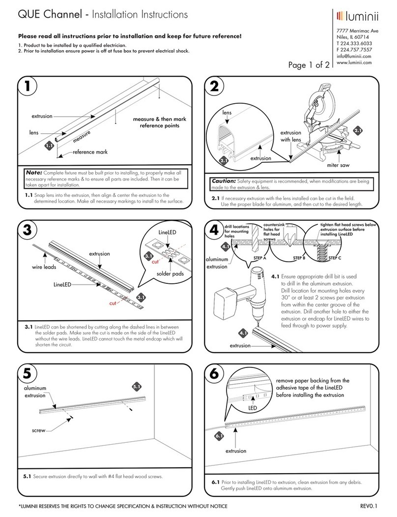
NOTE: When laying out the t-grid configuration on the ceiling, each
fixture requires 4-3/8" x length for the fixture to fit properly.
1
tile
width
4-3/8"
grid width for fixture
fixture
length
tile
width
4-3/8"
t-grid
1.1
Please read all instructions prior to installation and keep for future reference!
1. PRODUCT TO BE INSTALLED BY A QUALIFIED
ELECTRICIAN.
2. MORE THAN ONE PERSON IS RECOMMENDED FOR THIS
INSTALLATION.
3. SUITABLE FOR DRY LOCATIONS
4. TYPE IC
5. INHERENTLY PROTECTED
Page 1 of 4
7777 N. Merrimac Ave
Niles, IL 60714
T 224.333.6033
F 224.757.7557
[email protected]
www.luminii.com
Models TOVE-G-XX
Tove T-Grid - Installation Instructions
2
2.1 Install hanger wire (not provided) to
the fixture. Carefully bring the fixture to the
back of the t-grid area, followed by placing
the fixture on the t-grid. Additional
information below.
2.1
t-grid
fixture
suspension
cable
4
suspension cable
4.1 Use page 4 wiring diagram as reference, and make all the nessary wiring.
fixture 1
power
j-box
joining
j-box
fixture 2
conduit
T-grid
4.1
3
CAUTION: Make sure the hanger wire is secure to each endcap. Make sure to tie the end of the wire back through the first loop, bend the end of the wire up
to prevent the wire from untwisting.
(2X) Ø 0.20 hole
Ø 0.15 hole
#12 guage wire hanger
T-grid endcap
REV0.2 04132018
Please read all instructions prior to installation and keep for future reference!
1. PRODUCT TO BE INSTALLED BY A QUALIFIED
ELECTRICIAN.
2. MORE THAN ONE PERSON IS RECOMMENDED FOR THIS
INSTALLATION.
3. SUITABLE FOR DRY LOCATIONS
4. TYPE IC
5. INHERENTLY PROTECTED
Page 2 of 4
7777 N. Merrimac Ave
Niles, IL 60714
T 224.333.6033
F 224.757.7557
[email protected]
www.luminii.com
Models TOVE-G-XX
Tove T-Grid - Installation Instructions
6
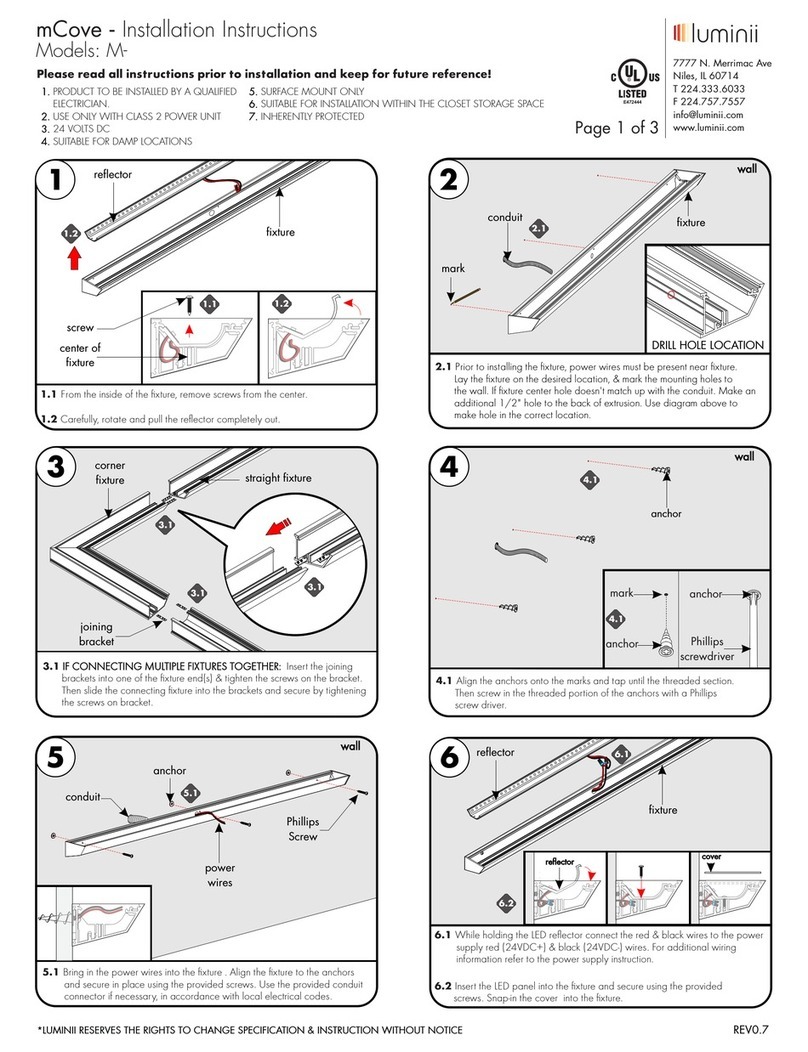
6.1 Prior to joining the sections together, connect electrical connections together. Join to the corresponding connector with the same colored wires.
6.2 Align male section to the female section, if necessary loosen nuts on the bolt brackets. Then insert all brackets into the female section, make sure there is
no gap in between sections, followed by tightening the outer bolts on bolt bracket first. Then tighten the 2 other bolts. Refer to bracket detail above,
washer must be behind bracket to work properly. Finally tighten the set screws on the plate bracket using the provided Allen wrench.
6.3 Secure LED board back into housing and secure the 4 screws back into place. Repeat for all remaining sections.
Bolt Bracket detail
Quick connects
not shown for clarity
6.3
LED module
male
female
plate bracket
bolt bracket
alignment
bracket
set screw
6.1
24VDC
bolt
bracket
nut
washer
secure
end bolts
1st
secure
inner bolts
2nd
low
voltage
ground
line
voltage
dimming
6.1
5
screw
LED module
5.1 Once all sections are installed & set to the proper hanging height from the ceiling. Loosen and remove the 4 screws from the fixture female
section LED module & carefully lower . Remove from only the sections that will get connected to (will be secured in the air, due to the safety wire)
the fixture male sections.
LED module
5.1
5.1
electrical quick connects
not shown for clarity
fixture
male section
Joining Continuous Rows together!
fixture
female section
*LUMINII RESERVES THE RIGHTS TO CHANGE SPECIFICATION & INSTRUCTION WITHOUT NOTICE REV0.2 04132018
*LUMINII RESERVES THE RIGHTS TO CHANGE SPECIFICATION & INSTRUCTION WITHOUT NOTICE
Please read all instructions prior to installation and keep for future reference!
4. TYPE IC
5. INHERENTLY PROTECTED
Page 3 of 4
7777 N. Merrimac Ave
Niles, IL 60714
T 224.333.6033
F 224.757.7557
[email protected]
www.luminii.com
Models TOVE-G-XX
Tove T-Grid - Installation Instructions
A
screw
A.2
A.1
fixture
lens
LED
module
fixture
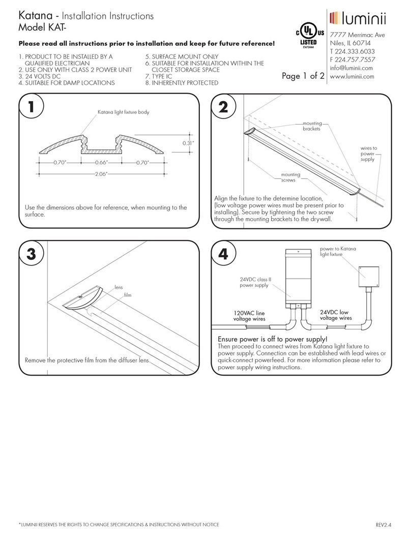
A.1 Carefully remove the lens from the inside of fixture. By pushing the
provided lens tool to the edge of the fixture. Then slowly pry the lens
down to take out completely.
A.2 Locate the dead module and remove screws. Release the wire clips from
the module, and remove security wire to completely remove the module.
A.3 Snap the new modules clips into the fixture followed by tightening screws
on the sides.
lens
tool mount
access module
6.1
B
B .1 Re-connect all quick connects for module.
B .2 Push all the wires & connectors into the housing and then align the LED
module into the housing and secure using the provided screws.
B .3 Snap lens back into the housing.
B .1
quick
connect
6.1
B .2
Replacing LED Module
1. PRODUCT TO BE INSTALLED BY A QUALIFIED
ELECTRICIAN.
2. MORE THAN ONE PERSON IS RECOMMENDED FOR THIS
INSTALLATION.
3. SUITABLE FOR DRY LOCATIONS
REV0.2 04132018
Please read all instructions prior to installation and keep for future reference!
4. TYPE IC
5. INHERENTLY PROTECTED
Page 4 of 4
7777 N. Merrimac Ave
Niles, IL 60714
T 224.333.6033
F 224.757.7557
[email protected]
www.luminii.com
Models TOVE-G-XX
Tove T-Grid - Installation Instructions
1. PRODUCT TO BE INSTALLED BY A QUALIFIED
ELECTRICIAN.
2. MORE THAN ONE PERSON IS RECOMMENDED FOR THIS
INSTALLATION.
3. SUITABLE FOR DRY LOCATIONS
*LUMINII RESERVES THE RIGHTS TO CHANGE SPECIFICATION & INSTRUCTION WITHOUT NOTICE REV0.2 04132018
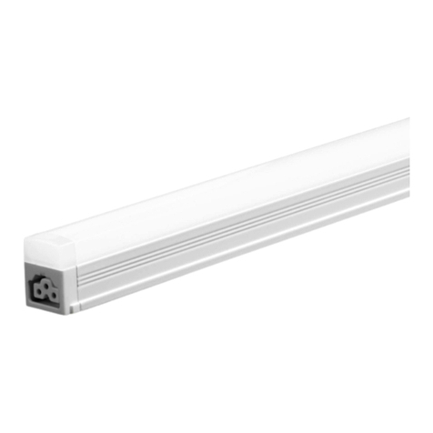
Wiring Diagrams
Lutron Ecosystem H-series wire power supply wiring
Lutron Ecosystem 3 wire power supply wiring
driver
3 way
dimming control
hot (blk)
dim hot (org)
neutral (wh)
ground (gr)
rd (+V)
blk (-V)
to line voltage
to LED module
eldoLED 0-10V Dimming power supply wiring
driver to LED module
to 0-10V
to line voltage
rd (+V)
blk (-V)
line (blk)
neutral (wh)
ground (gr)
0-10V (-)
0-10V (+)
eldoLED Dali power supply wiring
driver to LED module
to dali
to line voltage
rd (+V)
blk (-V)
line (blk)
neutral (wh)
ground (gr)
DALI (-)
DALI (+)
DALI (-)
DALI (+)
driver
to ecosystem bus
E1 (per)
E2 (per)
hot (blk)
neutral (wh)
ground (gr)
rd (+V)
blk (-V)
to line voltage
to LED module
driver / emergency battery pack
to constant line voltage
unswitched line (blk)
switched line (striped blk)
neutral (wh)
ground (gr)
test point (tp)
test switch/pilot light
test switch/pilot light must be connected to the battery during installation to work.
By just connecting the terminal connector to the battery.

This manual suits for next models

1

Other luminii Lighting Equipment manuals
luminii Optic Arts KM Series User manual

luminii

luminii Optic Arts KM Series User manual

luminii Kurba Pixel KBL-F-V-SPI User manual

luminii

luminii Kurba Pixel KBL-F-V-SPI User manual

luminii Kendo Closet Rod User manual

luminii

luminii Kendo Closet Rod User manual

luminii Optic Arts K45RC Series User manual

luminii

luminii Optic Arts K45RC Series User manual

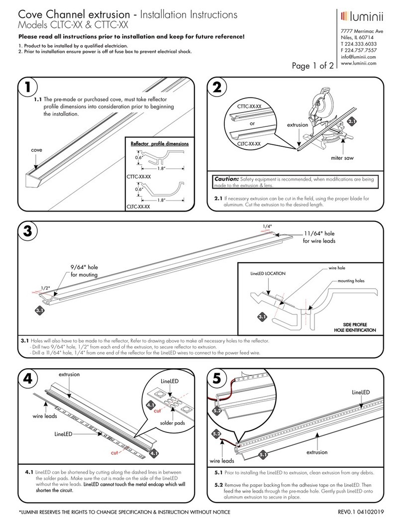
luminii CLTC Series User manual

luminii

luminii CLTC Series User manual

luminii Optic Arts KILO Channel User manual

luminii

luminii Optic Arts KILO Channel User manual

luminii QUE Channel User manual

luminii

luminii QUE Channel User manual

luminii Optic Arts PLAS Channel User manual

luminii

luminii Optic Arts PLAS Channel User manual

luminii KMC Series User manual

luminii

luminii KMC Series User manual

luminii Optic Arts PS010TW-96-24 User manual

luminii

luminii Optic Arts PS010TW-96-24 User manual

luminii Katana KAT User manual

luminii

luminii Katana KAT User manual

luminii Teava Suspension TEA-S Series User manual

luminii

luminii Teava Suspension TEA-S Series User manual

luminii senso LETO 4 User manual

luminii

luminii senso LETO 4 User manual

luminii RSLW8 Channel User manual

luminii

luminii RSLW8 Channel User manual

luminii RPLW80 Channel User manual

luminii

luminii RPLW80 Channel User manual

luminii Level User manual

luminii

luminii Level User manual

luminii Matrix Plus Series User manual

luminii

luminii Matrix Plus Series User manual

luminii Optic Arts CH-MD-LS-SF Series User manual

luminii

luminii Optic Arts CH-MD-LS-SF Series User manual

luminii PS010WD-96-24 User manual

luminii

luminii PS010WD-96-24 User manual

luminii mCove M User manual

luminii

luminii mCove M User manual

luminii Explorer Wall EXPW Series User manual
luminii

luminii Explorer Wall EXPW Series User manual

luminii Matrix Plus MP-DO-DW-22K-60K User manual

luminii

luminii Matrix Plus MP-DO-DW-22K-60K User manual

Popular Lighting Equipment manuals by other brands

ALPHA LITE A Series user manual

ALPHA LITE

ALPHA LITE A Series user manual

DTS XM 1200 SPOT user manual

DTS

DTS XM 1200 SPOT user manual

MULTIQUIP GLOBUG GBX12SK Operator's manual

MULTIQUIP

MULTIQUIP GLOBUG GBX12SK Operator's manual

Ayra ALO 060 user manual

Ayra

Ayra ALO 060 user manual

ACME ENERGY SPOT XA-400 SPOT user manual

ACME

ACME ENERGY SPOT XA-400 SPOT user manual

Dialight L-856 Quick start up guide

Dialight

Dialight L-856 Quick start up guide

Nicols WP 500 Z manual

Nicols

Nicols WP 500 Z manual

Defiant HB-1851 Quick reference guide

Defiant

Defiant HB-1851 Quick reference guide

Ultra-tow 31646 owner's manual

Ultra-tow

Ultra-tow 31646 owner's manual

Anolis ArcPad 48 Integral User instructions

Anolis

Anolis ArcPad 48 Integral User instructions

DOTLUX STUDIObutler 3542-330240 user manual

DOTLUX

DOTLUX STUDIObutler 3542-330240 user manual

leahua LH-C019 user manual

leahua

leahua LH-C019 user manual

Cameo CLNS120 user manual

Cameo

Cameo CLNS120 user manual

LNC A03176 manual

LNC

LNC A03176 manual

PROEL Four Rays Rainbow user manual

PROEL

PROEL Four Rays Rainbow user manual

Heliospectra SIERA user manual

Heliospectra

Heliospectra SIERA user manual

Velleman HQ POWER HQPE11001 user manual

Velleman

Velleman HQ POWER HQPE11001 user manual

WHITECROFT LIGHTING Concert EX3S quick start guide

WHITECROFT LIGHTING

WHITECROFT LIGHTING Concert EX3S quick start guide

manuals.online logo
manuals.online logoBrands
  • About & Mission
  • Contact us
  • Privacy Policy
  • Terms and Conditions

Copyright 2025 Manuals.Online. All Rights Reserved.