manuals.online logo
Brands
  1. Home
  2. •
  3. Brands
  4. •
  5. Speco
  6. •
  7. Security Camera
  8. •
  9. Speco HTFD4T Installation manual

Speco HTFD4T Installation manual

www.specotech.com
Installation and
Operation Manual
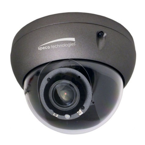
HTFD4T
USER INFORMATION:
Explanation of two Symbols
The lightning flash with arrowhead symbol, within anequilateral
triangle, isintended to alert the user to the presence of uninsulated
"dangerous voltage" within the product's enclosure that may be of
sufficient magnitude to constitute a risk of electric shock to persons.
The exclamation point within anequilateral triangle is intendedto
alert the user to the presence ofimportant operating and maintenance-
(servicing) instructions in the literature accompanying the appliance.
Read all of the safety and operating instructions before using the product.
Read Instructions
Save this manual for later use.
Retain Instructions
Unplugthis appliance from wall outlet before cleaning. Do not use liquid
cleaners or aerosolcleaners. Use a damp cloth for cleaning.
Cleaning
Do not place this product on an unstable cart, stand, or table.
Use only with a cart ora stand recommended by your supplier / reseller.
Mounting should follow the manufacturer's instructions, and should use a
mounting accessory recommended by manufacturer.
Do not installthe camera inextreme temperature conditions. Only use the
camera where temperatures are within the limits shown inthe specifications
section of the user guide. Be especially careful to provide ventilation when
operating under high temperatures.
Installation
This product should be operated only from the type of power source indicated
on the marking label. If you are notsure of the type of power supplied to
your home, consult your dealer or local power company.
Power source
IMPORTANT SAFETY INSTRUCTIONS:
FEATURES:
CAUTION!
TO REDUCE THE RISK OF ELECTRIC SHOCK, DO NOT REMOVE
COVER (OR BACK). NO USERSERVICEABLE PARTS INSIDE.
REFER SERVICING TO QUALIFIED SERVICE PERSONNEL.
CA UTIO N
RISK OF ELECTRIC SHOCK
DO NOT OPEN
•1/3 inch Progressive CMOS Image Sensor
•HD-TVI 1080p @ 30fps
•Adjustable motion detection (4 areas)
•Adjustable privacy mask (10 masks)
•Flexible Intensier® Technology (INTENSIFIER + Super IR)
•INTENSIFIER (X32)
•Digital Zoom (X12)
•SPECO DNR [ Digital Noise Reduction ]
•WDR [ Wide Dynamic Range ]
•BLC [ Backlight Compensation ]
•MIRROR
•DEFOG
•IP66 Weatherproofhousing
SPECIFICATIONS:
DIMENSIONS:
mm (inch)
Model
Image Sensor
Scanning System
Effective Pixels
Lens
Min Illumination
Backlight
Exposure
White Balance
Day& Night
Functions
Shutter
HD TVI Output
Resolution
Analog Video [ CVBS ]
Coaxial Communication
Supply Voltage
Power Consumption
Operating Temperature
Storage Temperature/ Humidity
HTFD4T
1/3 inch CMOS Image Sensor
Progressive Image Processing
1944 (H) x 1092 (V)
2.8-12mm Motorized Focus & Zoom Lens
INTENSIFIER (Max.) : 0 .0 005 Lux
IR LED ON : 0.0 Lux
OFF, WDR, BLC, HLC (ON / OFF)
AUTO / MANUAL
ATW INDOOR (2,500°K~7,500°K) /
ATW OUTDOOR (2,000°K~10,000°K)/ MANUAL / PUSH
Mechanical ICR Type
WDR, FLICKERLESS, SPECO DNR, ACE,DEFOG,
PRIVACY MASK, MIRROR, BLC
ESC : AUTO
TVI output 1.0Vp-p, 75 ohm
1920 x 1080p /30fps or 25fps
Analog Composite (1V±0.2 Vp-p)
Supports PELCO-C
24V AC (±20%) / 12VDC (±10%)
AC 600mA / DC 700mA, 8.4W (Max.)
-
14°F to 122°F (Heater on: -22°F to 122°F)
-
4°F to 140°F / 20% ~ 90% RH
REGULATORY NOTICE:
This equipment has beentested and found to comply with limits for a
Class A digital device, pursuant to part 15 of the FCC Rules.
These limits are designed to provide reasonable protection against
harmful interferencewhen the equipment is operated in a commercial
environment.
This equipment generates, uses, and can radiate radio frequency energy
and, if not installed and used in accordancewith the instruction manual,
may cause harmful interference to radio communications. Operation of
this equipment in a residential area is likely to cause harmful interference
in which case the user will be required to correct the interference at
their own expense.
Changes or modifications not expresslyapproved by the
manufacturer could void the user's authority to operate the equipment.
WARNING
When this camera is installed near equipment, like a wireless
communication device that emits a strong electromagnetic field,
some irregularity such as noise on the monitor screen may happen.
CAUTION
R50 (1.96)
92 (3.62)
43 (1.69)
Ø130
(5.11)
You mustbe fully aware of all the distinctive
featuresand precautions related tothis
camerabefore installing it.
(
438B
)
FLEXIBLEINTENSIFIER®
TECHNOLOGY
1080p HD-TVI Indoor/Outdoor
Dome Camera with Motorized Lens
TVI
1
1
2
2
Stick the guide pattern on the wall or ceiling.
Drill three holes according to the guide pattern.
Draw out power/ video wires to the connecting
places.
Attach the camera base to the ceiling or wall
using the supplied three screws.
Adjust desired focus and scene by turning and
moving the 3-Axis camera bracket by hand.
Put the dome cover over the base.
Lock the cover by tightening the screw using
the supplied L-wrench.
– To mount the camera:
CAMERA MOUNTING:
– The camera unit consists of the following parts:
COMPOSITION:
Installation should only
be performed by qualified service
personnel in accordance with the
National Electrical Code or applicable
local codes.
CAUTION
1
2
3
4
5
No.
Guide pattern
Dome base
Mounting screws
Dome cover
L-wrench for dome cover mounting
Part s
3
3
4
4
5
5
OSD MENU:
CAMERA CONTROLS:
SPECO TECH
PRESET INDOOR, OUTDOOR, LOW LIGHT, HALLWAY, LOBBY(WDR), ELEVATOR
EXIT ., RESET
MAIN SETUP
PUSH
ATW OUTDOOR
MANUAL
ATW INDOOR
WHITE BAL
HLC
WDR
BLC
OFF
BACKLIGHT

Design and specifications are subject tochange without notice.
Design and specifications are subject tochange without notice.
6
No.
Service monitor
connector
Part s
When installing the camera, connect a service monitor to
set angle of view and focus of the screen.
Rema rks
1
2
3
4
5
No.
Up (TELE)
Down (WIDE)
Left (NEAR)
Right (FAR)
Menu (Center)
Part s
Move the cursor up in the screen.
Move the cursor down in the screen.
Move the cursor left in the screen.
Move the cursor right in the screen.
Press straight down to openmenu or set.
• When pressing for 1 sec : AUTO FUCUS
• When pressing for few sec: Enter into CAMERA MENU
Rema rks
Menu navigation
Monitoring and switches
– It will automatically adjust the focus of video after switching Day/Night mode
– When powered on, focus will adjust automatically
Focus Operational Cases
– When there is a speedymovement, appearance and disappearanceofobjects
– When there is a noticeable change of illumination during the focus adjustment
– When the illumination is too low to recognize the objects
– When it is exposed to direct sunlight
– If a strong impactis applied to camera body
There will be malfunction of focus adjustment for the cases below.
D/N FOCUS
MODE
FOCUSNIGHT
DAY
SPECO DNR
OFF
ON
AUTO
FUSION IR
PRIVACY
SHADING
ACE
DEFOG
COLOR GAIN
GAMMA
MIRROR
D-ZOOM
SHARPNESS
IMAGE
ESC
LENS
LANGUAGE
BAUDRATE
VERSION
SYSTEM
ID DISPLAY
CAM TITLE
CAM ID
GENERAL
DOWN
RIGHT
LEFT
UP
6
6
5
5
DOWN
RIGHT
LEFT
UP
4
4
3
3
1
1
2
2
CONNECTION:
• Connect the video-out jack to the video-in jack of monitor.
• Connect the power adapter to the power input connector.
• The wire is non-polarized.
• Use 24V AC power source or 12V DC power source.
Video Output
GND
For 24V AC / 12V DC Power Type
1
2
3
No.
Video Output
Video Output
Power Input
Function
White
Yellow
Red
Terminal Color
HD-TVI
CVBS (Analog 960H)
24V AC (±20%)/ 12V DC (±10%)
Rema rks
12V DC
24V AC
AC AC
1
1
3
3
2
2
•The tape material butyl rubber is extended more than double
size. Winding tightly cable connection to prevent leaking
on cable.
•This product is IP66 waterproof certified one but the external
cable connection part is notwaterproof. Do not expose
cable on dropping water or humid place and be sure to
wring waterproof rubber tape.
PRECAUTION - Outdoor Installation
– Leaking expected at connected cable on outdoor installation. Use the
waterproof rubber tape winding up on cable connection as following picture.
1
1
2
2
3
3
Pan
360°
90°
Tilt
350°
Horizontal
• Connect cables.
A
A
A
A
• Winding rubber tape with half overlay on external
cable jacket (A) and cable connection.
• Winding each cable with using rubber tape.
HD-TVI
Analog
Power

Other Speco Security Camera manuals

Speco CVC5845DNV User manual

Speco

Speco CVC5845DNV User manual

Speco O8B8M User manual

Speco

Speco O8B8M User manual

Speco CVC-340LC User manual

Speco

Speco CVC-340LC User manual

Speco HT-INTB4 User manual

Speco

Speco HT-INTB4 User manual

Speco CVC-607CMTP User manual

Speco

Speco CVC-607CMTP User manual

Speco ONSIP 02D3 User manual

Speco

Speco ONSIP 02D3 User manual

Speco INTENSIFIER HTINTB8 User manual

Speco

Speco INTENSIFIER HTINTB8 User manual

Speco O8D9M User manual

Speco

Speco O8D9M User manual

Speco VL-183 User manual

Speco

Speco VL-183 User manual

Speco HDT471 User manual

Speco

Speco HDT471 User manual

Speco VLB9 User manual

Speco

Speco VLB9 User manual

Speco Deterrent O4BDD1M User manual

Speco

Speco Deterrent O4BDD1M User manual

Speco O4VD1N User manual

Speco

Speco O4VD1N User manual

Speco CVC-638 User manual

Speco

Speco CVC-638 User manual

Speco HT-647HRTP User manual

Speco

Speco HT-647HRTP User manual

Speco CVC6146SCSFF User manual

Speco

Speco CVC6146SCSFF User manual

Speco VIP2D1M User manual

Speco

Speco VIP2D1M User manual

Speco O5DH Reference guide

Speco

Speco O5DH Reference guide

Speco Intensifier VLINTT5 User manual

Speco

Speco Intensifier VLINTT5 User manual

Speco O4iB2 User manual

Speco

Speco O4iB2 User manual

Speco CVC627MT User manual

Speco

Speco CVC627MT User manual

Speco CVC-960IR User manual

Speco

Speco CVC-960IR User manual

Speco O4iD1M User manual

Speco

Speco O4iD1M User manual

Speco HTBIR1M User manual

Speco

Speco HTBIR1M User manual

Popular Security Camera manuals by other brands

Bushnell 119446C instruction manual

Bushnell

Bushnell 119446C instruction manual

Vivotek IP7330 user manual

Vivotek

Vivotek IP7330 user manual

Panasonic BL-WV10 Brochure & specs

Panasonic

Panasonic BL-WV10 Brochure & specs

Dahua Technology IPC-HDB3202-DI Series user manual

Dahua Technology

Dahua Technology IPC-HDB3202-DI Series user manual

Vivotek IP8336W Quick installation guide

Vivotek

Vivotek IP8336W Quick installation guide

System Q NiteDevil 24C IPCND705 instruction manual

System Q

System Q NiteDevil 24C IPCND705 instruction manual

Vitek Transcendent VTC-TNB5RMEA quick start guide

Vitek

Vitek Transcendent VTC-TNB5RMEA quick start guide

Grundig GCT-K0126V user manual

Grundig

Grundig GCT-K0126V user manual

Velleman CAMIP1 manual

Velleman

Velleman CAMIP1 manual

Novus NVIP-6DN5022H/IRH-1P user manual

Novus

Novus NVIP-6DN5022H/IRH-1P user manual

Steren CCTV-190 instruction manual

Steren

Steren CCTV-190 instruction manual

Digital Watchdog Starlight V3363D user manual

Digital Watchdog

Digital Watchdog Starlight V3363D user manual

Novus NVC-150B user manual

Novus

Novus NVC-150B user manual

imilab EC3 Pro user manual

imilab

imilab EC3 Pro user manual

Axis P3245 Series user manual

Axis

Axis P3245 Series user manual

iCatch IN-BL8102 user manual

iCatch

iCatch IN-BL8102 user manual

Huviron SK-2020 instruction manual

Huviron

Huviron SK-2020 instruction manual

Hiseeu WK-3C70 user manual

Hiseeu

Hiseeu WK-3C70 user manual

manuals.online logo
manuals.online logoBrands
  • About & Mission
  • Contact us
  • Privacy Policy
  • Terms and Conditions

Copyright 2025 Manuals.Online. All Rights Reserved.