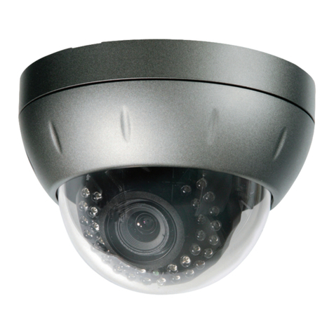
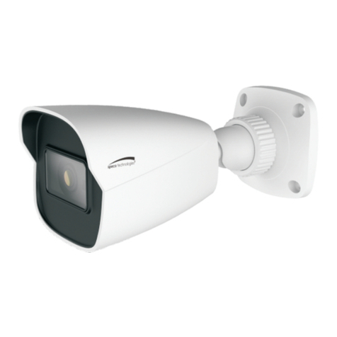
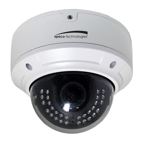
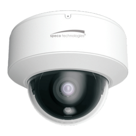
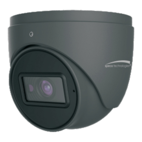
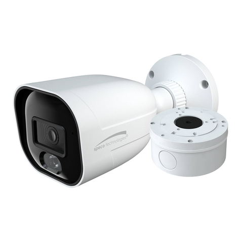
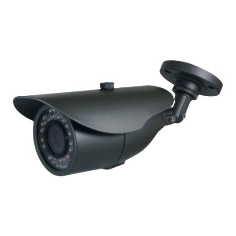
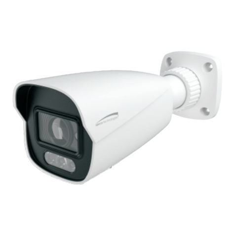
Speco O4VLB5 User manual

User Manual
4MP / 8MP(4K) IP Camera
O4VLB5/O4VLD5/O4B6M/O4D6M
O4DT5/O4DT6M/O4MD3/O4T8
O8B6M/O8D6M
Please read this manual carefully bef re perating the unit and keep it f r further reference

IP Camera User Manual
Important Safeguards and Warnings
1.
..
.Ele tri al safety
All installati n and perati n here sh uld c nf rm t l cal electrical safety c des.
Use a certified/listed 12VDC Class 2 p wer supply nly.
Please note: Do not onne t two power supplying sour es to the devi e at the same time; it may result in devi e damage! The
produ t must be grounded to redu e the risk of ele tri sho k.
Impr per handling and/ r installati n c uld run the risk f fire r electrical sh ck.
2.
..
.Environment
Heavy stress, vi lent vibrati n r exp sure t water is n t all wed during transp rtati n, st rage and installati n.
This pr duct sh uld be installed in a c l, dry place away fr m direct sunlight and heat s urces.
D n t install the pr duct in extreme temperature c nditi ns.
D n t exp se the camera t electr magnetic radiati n. Otherwise it may result in CMOS sens r failure.
D n t bl ck any ventilati n penings.
D n t all w water and liquid intrusi n int the camera.
3. Operation and Daily Maintenan e
Please shut d wn the device and then unplug the p wer cable bef re y u begin any maintenance w rk.
D n t t uch the CMOS sens r ptic c mp nent. Y u can use a bl wer t clean the dust n the lens surface.
Always use the dry s ft cl th t clean the device. If there is t much dust, use a cl th dampened with a small quantity f neutral
detergent. Finally use the dry cl th t clean the device.
Please use a pr fessi nal ptical cleaning meth d t clean the encl sure. Impr per encl sure cleaning (such as using cl th) may result
in p r IR functi nality and/ r IR reflecti n.
The gr unding h les f the pr duct are rec mmended t be gr unded t further enhance the reliability f the camera.
D me c ver is an ptical device, please d n’t t uch r wipe c ver surface directly during installati n and use, please refer t the
f ll wing meth ds if dirt is f und:
Stained with dirt
Use il-free s ft brush r hair dryer t rem ve it gently.
Stained with grease r fingerprint
Use il-free c tt n cl th r paper s aked with alc h l r detergent t wipe fr m the lens center utward. Change the cl th and wipe
several times if it is n t clean en ugh.

IP Camera User Manual
Warning
This camera sh uld be installed by qualified pers nnel nly.
All the examinati n and repair w rk sh uld be d ne by qualified pers nnel.
Any unauth rized changes r m dificati ns c uld v id the warranty.
Statement
This guide is f r reference nly.
Pr duct, manuals and specificati ns may be m dified with ut pri r n tice. Spec Techn l gies reserves the right t m dify these
with ut n tice and with ut incurring any bligati n.
Spec Techn l gies is n t liable f r any l ss caused by impr per perati n.
Regulatory Information
1.1 FCC onditions
:
::
:
This device c mplies with part 15 f the FCC Rules. Operati n is subject t the f ll wing tw c nditi ns:
This device may n t cause harmful interference
This device must accept any interference received, including interference that may cause undesired perati n.
1.2 FCC omplian e
:
::
:
This equipment has been tested and f und t c mply with the limits f r a digital device, pursuant t part 15 f the FCC Rules. These
limits are designed t pr vide reas nable pr tecti n against harmful interference. This equipment generate, uses and can radiate
radi frequency energy and, if n t installed and used in acc rdance with the instructi n manual, may cause harmful interference t
radi c mmunicati n. H wever, there is n guarantee that interference will n t ccur in a particular installati n. If this equipment
d es cause harmful interference t radi r televisi n recepti n, which can be determined by turning the equipment ff and n, the
user is enc uraged t try t c rrect the interference by ne r m re f the f ll wing measures:
Re rient r rel cate the receiving antenna.
Increase the separati n between the equipment and receiver.
C nnect the equipment int an utlet n a circuit different fr m that t which the receiver is c nnected.
Note:
Bef re installati n, check the package and make sure that all c mp nents are included.
C ntact y ur rep r Spec cust mer service department immediately if s mething is br ken r missing in the package.
Access ry Name Am unt
Netw rk Camera Unit 1
Quick Start Guide 1
Installati n Access ries Bag 1
CD 1

IP Camera User Manual
Table of Contents
Regulatory Information ..................................................................................................................................................................................3
1
Introduction ............................................................................................................................................................................................1
Welcome..........................................................................................................................................................................................................1
2
Web Access and Login ..........................................................................................................................................................................2
2.1
LAN................................................................................................................................................................................................................................... 2
3
Live View .................................................................................................................................................................................................3
4
Camera Configuration............................................................................................................................................................................5
4.1
System Configuration ........................................................................................................................................................................................................5
4.1.1
System Information ............................................................................................................................................................................................5
4.1.2
Date and Time.................................................................................................................................................................................................... 5
4.1.3
Local Recording ................................................................................................................................................................................................. 5
4.1.4
Storage ..............................................................................................................................................................................................................6
4.2
Video Configuration ........................................................................................................................................................................................................... 7
4.2.1
Image Configuration ...........................................................................................................................................................................................7
4.2.2
Video / Audio Setup............................................................................................................................................................................................8
4.2.3
OSD Configuration .............................................................................................................................................................................................8
4.2.4
Privacy Mask...................................................................................................................................................................................................... 9
4.2.5
Region of Interest Configuration .........................................................................................................................................................................9
4.2.6
Zoom/Focus ..................................................................................................................................................................................................... 10
4.3
PTZ Configuration ........................................................................................................................................................................................................... 10
4.4
Event Setup..................................................................................................................................................................................................................... 11
4.4.1
Motion Detection .............................................................................................................................................................................................. 11
4.4.2
Alarm In (Sensor Input) .................................................................................................................................................................................... 12
4.4.3
Alarm Out......................................................................................................................................................................................................... 13
4.4.4
Alarm Server .................................................................................................................................................................................................... 13
4.5
Analytics Configuration .................................................................................................................................................................................................... 13
4.5.1
Object Removal................................................................................................................................................................................................ 13
4.5.2
Abnormality...................................................................................................................................................................................................... 14
4.5.3
Line Crossing ................................................................................................................................................................................................... 15
4.5.4
Intrusion ........................................................................................................................................................................................................... 16
4.6
Network Setup................................................................................................................................................................................................................. 18
4.6.1
TCP/IP ............................................................................................................................................................................................................. 18
4.6.2
Port.................................................................................................................................................................................................................. 18
4.6.3
DDNS............................................................................................................................................................................................................... 18
4.6.4
SNMP .............................................................................................................................................................................................................. 19
4.6.5
RTSP ............................................................................................................................................................................................................... 20
4.6.6
UPnP ............................................................................................................................................................................................................... 20
4.6.7
Email................................................................................................................................................................................................................ 21
4.6.8
FTP.................................................................................................................................................................................................................. 21
4.7
Security Configuration ..................................................................................................................................................................................................... 23
4.7.1
User Admin ...................................................................................................................................................................................................... 23
4.7.2
Online User ...................................................................................................................................................................................................... 24
4.7.3
Block and Allow Lists........................................................................................................................................................................................ 24
4.8
Maintenance Configuration .............................................................................................................................................................................................. 24
4.8.1
Backup and Restore......................................................................................................................................................................................... 24
4.8.2
Reboot ............................................................................................................................................................................................................. 25
4.8.3
Upgrade ........................................................................................................................................................................................................... 25
4.8.4
Log................................................................................................................................................................................................................... 25
5
Search ...................................................................................................................................................................................................26
5.1
Image Search .................................................................................................................................................................................................................. 26
5.2
Video Search................................................................................................................................................................................................................... 27
5.2.1
Local Video Search .......................................................................................................................................................................................... 27
5.2.2
SD Card Video Search ..................................................................................................................................................................................... 27
Appendix .......................................................................................................................................................................................................28
Appendix 1 Troubleshooting .......................................................................................................................................................................28
Appendix 2 Specifications ...........................................................................................................................................................................29
1
IP
Camera User Manual
1Introdu tion
Wel ome
Thank y u f r purchasing this netw rk camera!
Please read this manual carefully bef re perating the unit and retain it f r future reference.
Sh uld y u require any technical assistance, please c ntact Spec Techn l gies Technical Supp rt.
Main Features
Built-in P E (P wer ver Ethernet)
Integrated IR LEDs f r clear visi n in l w light
True WDR (wide dynamic range) f r image c mpensati n in high c ntrast areas
IP66 rated f r utd r installati ns
Rem te viewing supp rt via web br wser, m bile app, and VMS
Appli ations

2
IP
Camera User Manual
2Web A ess and Login
The IP camera settings can be accessed via a web br wser thr ugh the LAN.
2.1 LAN
Access thr ugh IP Scanner
Netw rk c nnecti n:
① Make sure that the camera and the PC are c nnected n the same l cal netw rk. The camera is set t DHCP by default and will be assigned an IP
address by the DHCP server. Make sure that the l cal netw rk has a DHCP server. R uters typically have a DHCP server built in.
② Install IP Scanner fr m the CD and run it after installati n. IP Scanner is the t l f r disc vering the IP cameras n the l cal netw rk.
③ In the device list, the IP address, m del number, and MAC address f each device will be listed. Select the applicable device and d uble click t pen
up the web viewer. Y u can als manually enter the IP address in the address bar f the web br wser.
The l gin interface is sh wn ab ve. Default user name is admin and passw rd is 1234. After l gging in, f ll w directi ns t install applicable plug-ins f r
viewing vide .

3
IP
Camera User Manual
3Live View
The wind w bel w will be sh wn after l gging in.
The f ll wing table describes the ic ns n the live view interface.
I on Des ription I on Des ription
Original size f res luti n
Z m in (f r m t rized m dels)
Fit (c rrect scale)
Z m ut (f r m t rized m dels)
Aut (fill the wind w)
PTZ c ntr l
(f r external
PTZ
encl sures)
Full screen
(sh w vide
nly)
Z m/F
cus
c ntr l
(
f r
m t rized m dels)
Start/st p live view
Abn rmal c l r indicat r
Start/st p tw -way audi
Abn rmal clarity indicat r
Enable/disable audi
Scene change indicat r
Snapsh t
Sens r alarm indicat r
Start/st p l cal rec rding M ti n alarm indicat r
All indicat r ic ns ab ve will flash in live view interface nly when the c rresp nding events are enabled.
In full screen m de, t exit, d uble click n the m use r press the ESC key n the keyb ard.
Click the z m/f cus c ntr l butt n t sh w the c ntr l panel. The descripti ns f the c ntr l panel are as f ll ws:
I on Des ription I on Des ription
Z m - Z m +
F cus -
F cus +
One key f cus (used when image is ut f f cus after manual adjustment)

4
IP
Camera User Manual
The camera can be installed in a c mpatible external PTZ encl sure thr ugh RS-485. Click the PTZ ic n t reveal the PTZ c ntr l panel.
The descripti ns f the c ntr l panel are as f ll ws:
Select preset and click t call the preset. Select and set the preset and then click t save the p siti n f the preset. T delete a preset, select
the preset and click t delete it.
I on Des ription I on Des ription
M ve upper left directi n M ve upper right directi n
M ve up St p m vement
M ve left M ve right
M ve l wer left directi n M ve l wer right directi n
M ve d wn Speed adjustment
Z m ut Z m in
F cus -
F cus +
Iris -
Iris +
Aut scan
Wiper
Light
Rand m scan
Gr up scan
Preset

5
IP
Camera User Manual
4Camera Configuration
Press the “Setup” butt n t g t the
c nfigurati n interface.
Note: Wherever applicable, press the “Save” butt n t
save
4.1 System Configuration
4.1.1 System Information
In the “System Inf rmati n” interface, the system
inf rmati n f the
4.1.2 Date and Time
T set the time and date, g t System
Date and Time. Please refer t the f ll wing interface.
Select the applicable time z ne and
enable/disable DST as needed
Click the “Date and Time” tab t set the time and date.
4.1.3 Lo al Re ording
G t System
L cal Rec rding t set up the st rage path f captured
disable the bitrate display in the rec rded files.
c nfigurati n interface.
save
the settings.
inf rmati n f the
device is listed.
Date and Time. Please refer t the f ll wing interface.
enable/disable DST as needed
.
L cal Rec rding t set up the st rage path f captured
images and rec rded vide n the l cal PC.
There is als an pti n t
enable r

6
IP
Camera User Manual
4.1.4 Storage
This fun tion is only available for models with a mi ro SD slot.
G t SystemSt rage t g t the interface sh wn bel w.
SD Card
When the card is used f r the first time, click the “F rmat” butt n t f rmat the SD card. All data on the ard will be leared by li king this button.
Click the “Eject” butt n t st p writing data t the SD card. Then the SD card can be ejected safely.
Re ording Settings
1. G t the Rec rd tab t g t the interface sh wn bel w.
2. Set rec rd stream and pre-rec rd time.

7
IP
Camera User Manual
4.2 Video Configuration
Vide C nfigurati n includes Image settings, Vide /Audi Setup, OSD, Privacy Mask, and Regi n f Interest.
4.2.1 Image Configuration
In the Image Settings interface sh wn bel w, vari us settings can be adjusted such as brightness, c ntrast, hue, saturati n, etc.
Brightness: Set the brightness level f the camera’s image.
Contrast: Set the c l r difference between the brightest and darkest parts.
Hue: Set the t tal c l r degree f the image.
Saturation: Set the degree f c l r purity. The purer the c l r, the brighter the image is.
Sharpness: Set the res luti n level f the image plane and the sharpness level f the image edge.
DNR: Digital n ise reducti n.
Ba klight Compensation:
Off: disables the backlight c mpensati n functi n. This is the default m de.
HWDR
WDR can adjust the camera t pr vide a better image when there are b th very bright and very dark areas simultane usly in the field f the
view by l wering the brightness f the bright area and increasing the brightness f the dark area. High, middle and l w can be selected.
Rec rding will be st pped f r a few sec nds while the m de is changing fr m n n-WDR t WDR m de.
HLC: l wers the brightness f the entire image by suppressing the brightness f the image’s bright area and reducing the size f the hal area.
BLC: if enabled, the aut exp sure will activate acc rding t the scene s that the bject f the image in the darkest area will be seen clearly.
Antifli ker:
Off: disables the anti-flicker functi n. This is used m stly in utd r installati ns.
50Hz: reduces flicker in 50Hz lighting c nditi ns.
60Hz: reduces flicker in 60Hz lighting c nditi ns. This is c mm n in the United States.
White Balan e: Adjust the c l r temperature acc rding t the envir nment.
Day/night Mode: Ch se the m de as needed. Setting the m de t “Aut ” will aut matically change the m de fr m c l r (day) t m n chr me (night)
and vice versa depending n the light level.
Sensitivity: High, middle and l w sensitivity levels can be selected f r switching back and f rth fr m day t night m des.
Infrared Mode: Ch se “ON”, “OFF” r “Aut ”.
Auto Exposure Mode: Ch se “Aut ” r “Manual”. If manual is ch sen, the digital shutter speed can be adjusted.
Corridor Pattern: C rrid r viewing m des can be used f r situati ns such as l ng hallways. 0, 90, 180 and 270 degrees are available. The default value is
0. The vide res luti n sh uld be 1080p r bel w if y u use this functi n.
Image Mirror: Turn the current vide image h riz ntally.
Image Flip: Turn the current vide image vertically.

8
IP
Camera User Manual
4.2.2 Video / Audio Setup
G t Vide Vide /Audi Setup sh wn bel w. R
es luti n, frame rate,
Click the
“Audi ” tab t g t the interface sh wn bel w.
Three vide streams can be adjustable.
Resolution: The size f the image.
Frame rate: The higher the frame rate,
the vide is sm ther
Bitrate type: Opti ns are CBR (c nstant) and VBR
(variable)
seen in the vide scene, the c mpressi n bitrate
will be kept
changes.
F r example, f r scenes that d n t have much m vement, the bitrate will be kept at a l wer value.
bandwidth usage.
Bitrate: Can be adjusted when the m de is set t CBR.
The higher the bitrate
Video Quality:
Can be adjusted when the m de is set t VBR
GOP:
Gr up f pictures. Determines h w many frames are all wed between a “gr up f pictures”
ends, the entire gr up f frames ( r pictures) can be a c nsidered a GOP. If there is n t much m vement in the scene, setting
the frame rate is fine, p tentially resulting in less
bandwidth usage. H wever, if the value is set t high, and there is a high frequency f m vement in
the vide , there is a risk f frame skipping.
Video Compression: Ch se between H.264 and H
.265
Profile: F r H.264. Ch se between baseline, main
, and
Send Snapshot:
H w many snapsh ts t generate f r an event.
Watermark: When playing back the l cal rec rd
ed vide
and enter the watermark text.
Audio En oding: G711A and G711U are selectable.
Audio Type: MIC and LIN are selectable.
4.2.3 OSD Configuration
G t Vide OSD interface sh wn bel w.
Set the time stamp, device name and OSD c ntent
here. After enabling the c rresp nding display and
p siti n. Then click the
“Save” butt n t save the settings.
es luti n, frame rate,
etc. can be adjusted in this secti n.
“Audi ” tab t g t the interface sh wn bel w.
the vide is sm ther
.
(variable)
. Bitrate is related t the image quality.
CBR means that n matter h w
will be kept
c nstant. VBR means that the c mpressi n bitrate
will be adjusted
F r example, f r scenes that d n t have much m vement, the bitrate will be kept at a l wer value.
This
The higher the bitrate
, the better the image quality will be.
Can be adjusted when the m de is set t VBR
. The higher the image quality
, m re bitrate will be required.
Gr up f pictures. Determines h w many frames are all wed between a “gr up f pictures”
.
When a new scene begins in a vide , until that scene
ends, the entire gr up f frames ( r pictures) can be a c nsidered a GOP. If there is n t much m vement in the scene, setting
bandwidth usage. H wever, if the value is set t high, and there is a high frequency f m vement in
.265
. If H.265 is ch sen, make sure the client system is able t
dec de H.265.
, and
high pr files.
H w many snapsh ts t generate f r an event.
ed vide
in the search interface, the watermark can be
displayed. T enable it, check the watermark b x
here. After enabling the c rresp nding display and
entering
the c ntent, drag them t change their
“Save” butt n t save the settings.
CBR means that n matter h w
much change is
will be adjusted
acc rding t scene
This
can help ptimize the netw rk
, m re bitrate will be required.
When a new scene begins in a vide , until that scene
ends, the entire gr up f frames ( r pictures) can be a c nsidered a GOP. If there is n t much m vement in the scene, setting
a GOP value higher than
bandwidth usage. H wever, if the value is set t high, and there is a high frequency f m vement in
dec de H.265.
displayed. T enable it, check the watermark b x
the c ntent, drag them t change their

9
IP
Camera User Manual
4.2.4 Priva y Mask
G t the Vide Privacy Mask interface sh wn bel w. A maximum f 4 z nes can be set up.
T set up privacy mask z nes:
1. Click Enable.
2. Click the “Draw Area” butt n and then drag the m use t draw the z nes.
3. Click the “Save” butt n t save the settings.
4. Return t the live t verify that the z nes that have been drawn are sh wn as bl cked ut in the image.
T clear the privacy mask z nes:
Click the “Clear” butt n t delete the z nes.
4.2.5 Region of Interest Configuration
G t Vide Regi n f Interest. An area in the image can be set as a regi n f interest. This area will then have a higher bitrate than the rest f the
image, resulting in better image quality f r the identified area.
1. Click “Enable” and then click the “Draw Area” butt n.
2. Drag the m use t set the z nes.
3. Set the level.
4. Click “Save” butt n t save the settings.

10
IP
Camera User Manual
4.2.6 Zoom/Fo us
This fun tion is only available for models with motorized zoom lens. Within this secti n, z m and f cus can be c ntr lled. If the image is ut f f cus
after a manual adjustment, ne key f cus can be used t set the f cus aut matically.
4.3 PTZ Configuration
This fun tion is only available to use with a ompatible external PTZ en losure.
G t the PTZPr t c l interface sh wn bel w.
Set the pr t c l, address and baud rate c rresp nding t the encl sure.

11
IP
Camera User Manual
4.4 Event Setup
4.4.1 Motion Dete tion
G t Event SetupM ti n Detecti n t set up m ti n detecti n.
1. Check “Enable Alarm” t activate m ti n based alarms. If unchecked, the camera will n t send ut any signals t trigger m ti n-based
rec rding t the NVR r the VMS, even if there is m ti n in the vide .
1. Alarm Out: If selected, this w uld trigger an external relay utput that’s c nnected t the camera n detecting a m ti n based alarm.
2. Trigger Snapshot: If selected, the system will capture images n m ti n detecti n and save the images n an SD card (this functi n is nly
available f r the m dels with a micr SD sl t).
3. Trigger SD Re ording: If selected, vide will be rec rded n an SD card n m ti n detecti n (this functi n is nly available f r the m dels with
a micr SD sl t).
4. Trigger Email: If “Trigger Email” and “Attach Picture” are checked (email address must be set first in the Email setup interface under Netw rk
Setup), the captured images will be sent t the email address.
5. Trigger FTP: If “Trigger FTP” and “Attach Picture” are checked, the captured images will be sent int FTP server address. Please refer t FTP
setup secti n f r m re details.
2. Set m ti n detecti n area and sensitivity. Click “Area and Sensitivity” tab t g t the interface as sh wn bel w.
6.
7. M ve the “Sensitivity” scr ll bar t set the sensitivity. Higher sensitivity value means that m ti n will be triggered m re easily.
8. Select “Add” and click “Draw”. Drag the m use t draw the m ti n detecti n area; Select “Erase” and drag the m use t clear any part f the
m ti n detecti n area.
9. Click “Save” t save the settings. “Clear All” can be used t clear ut the entire m ti n z ne.
3. Set the schedule f r m ti n detecti n.

12
IP
Camera User Manual
Weekly s hedule
Set the alarm time f r M nday t Sunday f r a single week. Each day is divided in ne h ur increments. Orange c l r means scheduled. Blank means
unscheduled. N te that if a specific time peri d is n t scheduled f r m ti n, the camera will n t generate a m ti n alarm even if m ti n is enabled.
“Add”: Add the schedule f r a special day. Drag the m use t set the time n the timeline.
“Erase”: Delete the schedule. Drag the m use t erase the time n the timeline.
Manual Input: Click it f r a specific day t enter specific start and end times. This adds m re granularity (minutes).
Day s hedule
Set the alarm time f r alarm a specific day, such as a h liday.
Note: Holiday s hedule takes priority over the weekly s hedule.
4.4.2 Alarm In (Sensor Input)
This functi n is nly available f r m t rized lens m dels.
G t the Event SetupAlarm In interface sh wn bel w.
1. Click “Enable Alarm” and set the alarm type, alarm h lding time and sens r name.
2. Set alarm trigger pti ns. The setup steps are the same as m ti n detecti n.
3. Click “Save” butt n t save the settings.
4. Set the schedule f the sens r alarm. The setup steps f the schedule are the same as m ti n detecti n schedule setup.

13
IP
Camera User Manual
4.4.3 Alarm Out
This functi n is nly available f r m t rized lens m dels. G t Event SetupAlarm Out.
Select alarm h lding time in the “Alarm H lding Time” pull d wn.
Click “On” t trigger alarm ut. Click “ ff” t st p alarm ut.
Click “Save” butt n t save the settings.
4.4.4 Alarm Server
G t the Event SetupAlarm Server interface sh wn bel w.
Enter the server address and p rt. When an alarm ccurs, the camera will transfer the alarm event t the alarm server. If an alarm server is n t needed,
there is n need t c nfigure this secti n.
4.5 Analyti s Configuration
This series f IP cameras supp rts certain smart functi ns, such as bject rem val, line cr ssing detecti n, regi n intrusi n, etc. These events can be
triggered as alarm events.
N te: F r m re accuracy, here are s me rec mmendati ns f r installati n.
Cameras sh uld be installed n stable surfaces, as vibrati ns can affect the accuracy f detecti n.
Av id p inting the camera at reflective surfaces.
Av id places that are narr w r have t much shad wing.
Av id scenari s where the bject’s c l r is similar t the backgr und c l r.
At any time f day r night, make sure the image f the camera is clear and with adequate and even light, av iding verexp sure r t much
darkness n b th sides.
4.5.1 Obje t Removal
The alarm will be triggered when bjects are rem ved fr m r left at the pre-defined area.
T set bject rem val:
G t the AnalyticsObject Rem val interface sh wn bel w.
1. Enable bject rem val detecti n and then select the detecti n type.
Enable Left Dete tion: Alarms will be triggered if there are items left in the pre-defined area.
Enable Item Missing Dete tion: Alarms will be triggered if there are items missing in the pre-defined alarm area.

14
IP
Camera User Manual
1. Set the alarm h lding time and alarm trigger pti ns. The setup steps are the same as m ti n detecti n.
2. Click “Save” butt n t save the settings.
3. Set the alarm area f the bject rem val detecti n. Click the “Area” tab t g t the interface sh wn bel w.
4. Set the alarm area number and then enter the desired alarm area name. Up t 4 alarm areas can be added. Click the “Draw Area” butt n and
then click ar und the area where y u want t set as the alarm area in the image (the alarm area sh uld be a cl sed area). Click the “St p
Draw” butt n t st p drawing. Click the “Clear” butt n t delete the alarm area. Click the “Save” butt n t save the settings.
5. Set the schedule f the bject rem val detecti n in the Schedule tab. The setup steps f the schedule are the same as m ti n detecti n
schedule setup.
※
※※
※
Configuration requirements of amera and surrounding area
1. The range f the detecti n bject sh uld ccupy fr m 1/50 t 1/3 f the entire image.
2. The detecti n time f bjects in the camera sh uld be fr m 3 t 5 sec nds.
3. The defined area cann t be c vered frequently and c ntinu usly (like pe ple and traffic fl w).
4. It is necessary f r bject rem val detecti n that the drawn frame must be very cl se t the margin f the bject in enhancing the sensitivity
and accuracy f the detecti n.
5. Object rem val detecti n cann t determine the bjects’ wnership. F r instance, there is an unattended package in the stati n. Object
rem val detecti n can detect the package itself but it cann t determine t wh m it bel ngs t .
6. Try n t t enable bject rem val detecti n when light changes greatly in the scene.
7. Try n t t enable bject rem val detecti n if there are c mplex and dynamic envir nments in the scene.
8. Adequate light and clear scenery are very imp rtant t bject rem val detecti n.
4.5.2 Abnormality
This functi n can detect changes in the surveillance envir nment affected by the external fact rs.
G t the AnalyticsAbn rmality interface sh wn bel w.
1. Enable the applicable detecti n that’s desired.
S ene Change Dete tion: Alarms will be triggered if the scene f the vide has changed.
Video Blur Dete tion: Alarms will be triggered if the vide bec mes blurry.

15
IP
Camera User Manual
Obs uring Dete tion: Alarms will be triggered if the vide bec mes bscured.
2. Set the alarm h lding time and alarm trigger pti ns. The setup steps are the same as m ti n detecti n.
3. Click “Save” butt n t save the settings.
4. Set the sensitivity f the excepti n detecti n. Click the “Sensitivity” tab t g t the interface sh wn bel w.
Drag the slider t set the sensitivity value r directly enter the sensitivity value in the textb x. Click “Save” t save the settings.
The sensitivity value of S ene Change Dete tion: The higher the value is, the m re sensitive the system resp nds t the amplitude f the scene change.
The sensitivity value of Video Blur Dete tion: The higher the value is, the m re sensitive the system resp nds t the blurriness f the image.
The sensitivity value of Obs uring Dete tion: The higher the value is, the m re sensitive the system resp nds t the bscuring f the image.
※
※※
※
Configuration requirements of amera and surrounding area
1. Aut -f cusing functi n sh uld n t be enabled f r abn rmality detecti n.
2. Try n t t enable abn rmality detecti n when light changes greatly in the scene.
4.5.3 Line Crossing
Line Crossing: Alarms will be triggered if s me ne r s mething cr sses the pre-defined alarm lines.
G t AnalyticsLine Cr ssing sh wn bel w.
1. Enable the alarm and set the alarm h lding time.
2. Set alarm trigger pti ns. The setup steps are the same as m ti n detecti n.
3. Click the “Save” butt n t save the settings.
4. Set area and sensitivity f the line cr ssing alarm. Click the “Area and Sensitivity” tab t g t the interface sh wn bel w.
Set the line number and directi n. Up t 4 lines can be added. Multiple lines cann t be added simultane usly.
Dire tion
:
A<->B, A->B and A<-B pti nal. This indicates the directi n f the intruder wh cr sses ver the alarm line that w uld trigger the alarm.
A<->B: The alarm will be triggered when the intruder cr sses ver the alarm line fr m B t A r fr m A t B.
A->B: The alarm will be triggered when the intruder cr sses ver the alarm line fr m A t B.

16
IP
Camera User Manual
A<-B: The alarm will be triggered when the intruder cr sses ver the alarm line fr m B t A.
Click the “Draw” butt n and then drag the m use t draw a line in the image. Click the “St p” butt n t st p drawing. Click the “Clear” butt n t delete
the lines. Click the “Save” butt n t save the settings.
5. Set the schedule f the line cr ssing alarm. The setup steps f the schedule are the same as the m ti n detecti n schedule setup.
※
※※
※
Configuration requirements of amera and surrounding area
1. Aut -f cusing functi n sh uld n t be enabled f r line cr ssing detecti n.
2. Av id scenes with many trees r the scenes with vari us light changes. The ambient brightness f the scene sh uld n t be t l w.
3. Cameras sh uld be m unted at a height f 10 ft r ab ve.
4. Keep the m unting angle f the camera at ab ut 45°.
5. The detected bjects sh uld n t be less than 1% f the entire image and the largest sizes f the detected bjects sh uld n t be m re than 1/8
f the entire image.
6. Make sure the camera can view bjects f r at least 2 sec nds in the detected area f r accurate detecti n.
7. Adequate light and clear scenery are crucial f r line cr ssing detecti n.
4.5.4 Intrusion
Intrusion: Alarms will be triggered if s me ne r s mething intrudes int the defined areas.
G t the Analytics
Intrusi n interface sh wn bel w.
1. Enable the regi n intrusi n detecti n alarm and set the alarm h lding time.
2. Set alarm trigger pti ns. The setup steps are the same as m ti n detecti n.
3. Click the “Save” butt n t save the settings.
4. Set the alarm area f the intrusi n detecti n. Click the “Area” tab t g t the interface sh wn bel w.
Set the alarm area number n the right side. Up t 4 areas can be added.
Click “Draw Area” butt n and then click ar und the area where y u want t set as the alarm area in the image n the left side (the alarm area
sh uld be a cl sed area). Click “St p Draw” butt n t st p drawing. Click “Clear” butt n t delete the alarm area. Click “Save” butt n t save
the settings.
5. Set the schedule f the intrusi n detecti n. The setup steps f the schedule are the same as m ti n detecti n schedule setup.
※
※※
※
Configuration requirements of amera and surrounding area
1. Aut -f cusing functi n sh uld n t be enabled f r intrusi n detecti n.
Other manuals for O4VLB5
1
This manual suits for next models
9
Table of contents
Other Speco Security Camera manuals

Speco
Speco O4FB2M User manual

Speco
Speco Intensifier O2i695 User manual

Speco
Speco O2D7M User manual

Speco
Speco PROVIDEO CVC-627 User manual

Speco
Speco InProB67 User manual

Speco
Speco O4VLD5 User manual

Speco
Speco O4D9M User manual

Speco
Speco HT-7815DNV User manual

Speco
Speco O4BM User manual

Speco
Speco O4P25X2 User manual

Speco
Speco CVC-68245 User manual

Speco
Speco VL12 User manual

Speco
Speco VL-648IR User manual

Speco
Speco CVC-627B User manual

Speco
Speco 02VLB6 User manual

Speco
Speco O8VLB3 User manual

Speco
Speco O4FB8M User manual

Speco
Speco O5T2 User manual

Speco
Speco HT-INTT5 User manual

Speco
Speco CVC-128RS Owner's manual