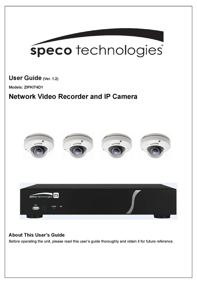
Speco PVS-3 User manual

speco technologies
TM
PVS - 3
Color Observation System
14” Monitor with Built-In Quad Splitter
And 4-CH Switcher
With enhanced audio output
speco technologies
200 New Highway
Amityville, NY 11701
Toll Free : 1-800-645-5516
In Metro NY : 631-957-8700
www.specotech.com
OPERATION MANUAL

CAUTION : TO REDUCE THE RISK OF ELECTRICSHOCKDONOT
REMOVE COVER (OR BACK). NO USER-
SERVICEABLE PARTS INSIDE, REFER FOR SERVICE
TO QUALIFIED SERVICE PERSONNEL.
The lightning flash with arrowhead symbol, within
an equatorial triangle, is intended to alert the user
to the presence of un-insulated “dangerous
voltage” within the product’s enclosure that may be
of sufficient magnitude to constitute a risk of
electric shock to persons.
The exclamation point within an equilateral triangle
is intended to alert the user to the presence of
important operating and maintenance (servicing)
instructions in the literature accompanying the
appliance.
THE GRAPHIC SYMBOLS WITH SUPPLEMENTAL MARKING IS
APPLIED ON THE REAR SIDE OF THE SUBJECT MONITOR.
WARNING: To prevent fire or shock hazard, do not expose this
appliance to rain, water, and wet locations. Do not
insert any metallic object through ventilation grilles.
IMPORTANT SAFETY INSTRUCTIONS
This video monitor equipment is provided with a polarized
alternating-current line plug (a plug having one blade wider than the
other). This plug will fit into the power outlet only one way. This is a
safety feature. If you are unable to insert the plug fully into the
outlet, try reversing the plug. If the plug should still fail to fit, contact
your electrician to replace your obsolete outlet. Do not defeat the
safety purpose of the polarized plug.
CAUTION
RISK OF ELECTRIC SHOCK DO NOT OPEN
PVS - 3 PVS - 3

8. TROUBLE SHOOTING
If the system does not function properly, check following
points before contacting the service center.
No Problem Possible Solutions
1 No Video 9Verify power to all pieces of
equipment in the system.
9Verity that the power switches are in
the ON position
9Verify that the cameras are property
hooked up
2 Video
No control
9Turn the power OFF for 30 seconds
and then turn it ON again
INDEX
SECTION 1
1. PURPOSE OF THIS PRODUCT 1
2. FEATURES &SPECIFICATIONS 2
2-1. Monitor Features 2
2-2. Specifications 2
3. IMPORTANT SAFEGUARDS
4
SECTION 2
4. CONNECTIONS 11
5. INSTALLATION 15
5-1. Basic System Installation 15
5-2. Installation with a VCR or Time Lapse
Recorder
16
5-3. Installation with Sensor 17
SECTION 3
6. OPERATION 19
6-1. Monitor Basis Establishment 19
6-2. Change Function 20
6-3. Alarm Function 23
6-4. How to use Menu for Setup. 24
7. IR REMOTE CONTROL 33
7-1. Function Selection Keys 34
8. TROUBLESHOOTING 35
PVS - 3 PVS - 3

SECTION 1
1. PURPOSE OF THIS PRODUCT
The purpose of this system is to provide an economical, but
effective method to monitor more than one area with video
cameras. This monitor has the following features to enable the
users to get the best for their money and efforts.
-Accepts NTSC or PAL Video format.
-NTSC: 720 x 480 Pixels.
-P A L : 720 x 540 Pixels.
-Real time quad picture display.
-PIP (Picture-In-Picture) function.
-2x ZOOM with Vertical and Horizontal interpolation.
-Full-screen display of one camera.
-Four-position sequential switcher.
-Programmable dwell times to include cameras and the quad
display in the sequential switching mode.
-Alarm capability allows alarm devices to be connected to the
monitor.
-Alarm holds time: 00 to 59 seconds.
-On-screen-display and programmable menus.
-User-programmed data is protected battery back up.
-Freeze capability (can freeze a picture).
-Program selectable borderline.
-Motion function available. (option)
7-1. Function select keys.
1. :Turns Power to monitor ON/OFF
2. 1 - 4 : Allows user to select individual cameras.
3. FRZ 1 : When the user wants to freeze the CH1 by using
Remote control in quad mode.
4. FRZ 2 : When the user wants to freeze the CH2 by using
Remote control in quad mode.
5. FRZ 3 : When the user wants to freeze the CH3 by using
Remote control in quad mode.
6. FRZ 4 : When the user wants to freeze the CH4 by using
Remote control in quad mode.
7. TALK : For voice communications in full screen.
8. AUDIO SEL : Sets monitor to Audio feature.
9. MENU : Call up the MENU Feature.
10. ZOOM : Sets monitor to Zoom Feature.
11. VCR : Sets monitor to VCR Mode.
12. AUTO1 : Sets monitor to display each camera
sequentially.
13. PIP : Sets monitor to PIP Mode.
14. AUTO2 : Displays PIP mode & sub-channel sequencing.
15. AUTO3 : Displays PIP mode & main-channel sequencing.
16. QUAD : Displays the pictures in quadrant mode.
17. ▲, ►, ▼, ◄, ■: Used the change key in Zoom, Menu,
Volume, Setup Menu.
18. VOL : Sets the volume sound.
19. SETTUP : Select Bright, Contrast. Color, Tint, Sharpness.
PVS - 3 PVS - 3
-01- - 34 -

7. IR REMOTE CONTROL
This color quad monitor is also operated by an IR Remote
Controller.
2. FEATURES & SPECIFICATIONS
2-1. Monitor Features
CCTV SYSTEM
AUTO2 AUTO3
PIP
QUADZOOM VCR AUTO1
FRZ4
FRZ3
VOL
SETUP
VOL
FRZ1
FRZ2
MENU
TALK SETUP
AUDIO
SEL
- Multiple input
Composite video channels from 1 to 4 with loop-
through
VCR input
- Horizontal resolution
Center : 380 lines (NTSC / PAL)
Corner : 340 lines (NTSC / PAL)
- Comb filter
Improves picture quality significantly.
- Functions
Tint, color, contrast, brightness, sharpness, audio
volume – all manually adjustable
2-2. Specifications
- System
NTSC : 525 lines, 60 fields per second
P A L : 625 lines, 50 fields per second
- Input Signal
Composite video, sync. Negative
- Sub-carrier Frequency Sync. Range
3.579545MHz ± 200Hz at room temperature.
4.433619MHz ± 200Hz at room temperature.
PVS - 3 PVS - 3
-33- - 02 -

- High Voltage
22.5KV ± 500V
- Convergence
At center of picture: less than 1.0 mm
At corner of picture: less than 1.4 mm
- Brightness
55 ft/l (Brightness, Contrast. Max.)
- Operating Temperature
32 to 104 degree F
0 to 40 degree C
- Humidity
0% to 90% (non-condensing)
- Connectors
BNC Connector : video in
6-pin mini DIN : video in, audio in/out, +12V DC
out, alarm (PIR) in
RCA jack : VCR in/out, slave video/audio
out
- Power Source
AC 90V ~ 240V, 50/60Hz, 65W
Free Voltage Switching Power Supply
- Dimension
Width : 14.3 inch (36.4 cm)
Height : 13.5 inch (34.4 cm)
Depth : 15.3 inch (38.9 cm)
- Weight
31.74lb (16.4Kg, including packing)
b. EXIT
- Place the green color character to the EXIT with the ▼
and the ▲buttons.
- Press the VCR / Enter Button to exit the MENU setup
mode.
PVS - 3 PVS - 3
-03- - 32 -

d. ALARM TIME
The ALARM TIME is to be set alarm time on each channel.
- Place the cursor to the ALARM TIME with the ▼and the
▲Buttons.
- Select the channel you want to set the alarm time by
using the ◄, ►Buttons.
- Press the ▼or the▲Button for setting the ALARM time.
It can be set from 00 to 59 seconds.
- Press the VCR / Enter Button to stop flashing the ALARM
TIME.
6-4-4. SPECIAL MENU
Press the PIP/MENU button again, the following menu screen
will be displayed
SPECIAL MENU
a. DEFAULT SETTING
This function is to load for INITIAL data.
- [Y] :Enable INITIAL date loading.
- [N] :Disable INITIAL data loading.
3. IMPORTANT SAFEGUARDS
Important safety instructions shall be provided with each
appliance. These safety instructions may be in the form of a
separate booklet, separate sheet, or part of the instruction
manual. If included in the instruction manual, the safety
instructions shall be located after the graphical symbols
explanation but before and separated in format from the other
material. The instructions need not be in the order shown and
they need not be verbatim.
The use of a different font for the individual headings is
optional
(1) Read Instructions - All the safety and operating
instructions should be read before the product is operated.
(2) Retain Instructions - The safety and operating
instructions should be retained for future reference.
[SPECIAL]
DEFAULT SETTING
: [ N ]
EXIT []
(3) Heed Warnings - All warnings on the product and in the
operating instructions should be adhered to.
(4) Follow Instructions – All operating and use instructions
should be followed.
(5) Cleaning - Unplug this product from the wall outlet before
cleaning. Do not use liquid cleaners or aerosol cleaners.
Use a damp cloth for cleaning.
(6) Attachments - Do not use attachments not recommended
by the product manufacturers as they may cause hazards.
(7) Water and Moisture - Do not use this product near water -
for example, near a bath tub, wash bowl, kitchen sink, or
laundry tub, in a wet basement, or near a swimming pool,
PVS - 3 PVS - 3
-31- - 04 -

and the like.
(8) Accessories - Do not place this product on an unstable
cart, stand tripod, bracket, or table. The product may fall,
causing serious injury to a child or adult, and serious
damage to the product. Use only with a cart, stand, tripod,
bracket, or table recommended by the manufacturer, or
sold with the product. Any mounting of the product
should follow manufacturer’s instruction and should use a
mounting accessory recommended by the manufacturer
(9) A product and cart combination should be moved with care.
Quick stops, excessive force, and uneven surfaces may
cause the product and cart combination to overturn.
This symbols to be included in the
Important Safeguards of applicable
units adjacent to Item 9.
(10) Ventilation - Slots and openings
in the cabinet are provided for
ventilation and to ensure reliable
operation of the product and to
protect it from overheating, and these openings must not
be blocked or covered. The openings should never be
blocked by placing the product on a bed, sofa, rug, or
other similar surface. This product should not be placed in
a built-in installation such as a bookcase or rack, unless
proper ventilation is provided or manufacturer's instruction
has been adhered to.
(11) Power Source - This product should be operated only from
the type of power source indicated on the marking label. If
6-4-3. BUZZER/ALARM
Press the PIP/Menu button again, the following menu will
be displayed.
BUZZER/ALARM MENU
[BUZZER/ALARM]
KEY BUZZER
: [ Y ]
LOSSBUZZER :[N]
ALARM BUZZER
: [ Y ]
ALARM TIME (S) : CH1 CH2 CH3 CH4
03 03 03 03
EXIT []
a. KEY BUZZER
[Y] - When use this button, buzzer voice sound.
[N] - When use this button, buzzer is dumb.
b. LOSS BUZZER
[Y] - Buzzer sounds when the signal is lost between camera
and the monitor. The screen moves to quad mode for
displaying disconnected camera channel and the
letter “L” displays on the channel that has been
disconnected.
[N] - Buzzer doesn’t sound regardless of connection (signal).
It displays continuously with sign of disconnecting.
c. ALARM BUZZER
[Y] – When this button is pressed, alarm buzzer is activated.
[N] - When this button is pressed, the alarm buzzer function
is cancelled.
PVS - 3 PVS - 3
-05- - 30 -

- Place the green color character to the DWELL TIME
using the ◄, ▼, ▲and the ►Buttons, and press the
VCR / Enter Button to flash the DWELL TIME and set it
using the ▼or the ▲Buttons. Press the VCR / Enter
Button again to set it.
- Press the PIP/Menu Button to return to the menu.
c. ALM (ALARM)
There are three factors to provide the input alarm source.
Normally Open (N.O), Normally Closed (N.C) and OFF,
which can be selected in the channel menu by pressing
the QUAD button once or twice.
d. LOAD
75 ohms normally terminate the video signal. But in case
the signal is distributed to a number of lines, only one of
lines is to be terminated by 75 ohms (1Vp-p), while the
other lines are terminated by High impedance status
(2Vp-p). The 75 ohms or the HI can be selected by
pressing the ENTER button.
If you are not sure of the type of power supply to your
location, consult your product dealer or local power
company. For products intended to operate from battery
power, or other sources, refer to the operating instructions.
(12) Grounding or Polarization - This product may be
equipped with a polarized alternating-current plug (a plug
having one blade wider than the other). This plug will fit
into the power outlet only one way. This is a safety feature.
If you are unable to insert the plug fully into the outlet, try
reversing the plug. If the plug should still fail to fit, contact
your electrician to replace your obsolete outlet. Do not
defeat the safety purpose of the polarized plug.
(13) Power - Cord protection-Power supply cords should be
routed so that they are not likely to be walked on or
pinched by items placed upon or against them, paying
particular attention to cords at plugs, convenience
receptacles, and the point where they exit from the product.
(14) Protective Attachment Plug – The product is equipped
with an attachment plug having overload protection. This is
a safety feature. See Instruction Manual for replacement or
resetting of protective device. If replacement of the plug is
required, be sure the service technician has used a
replacement plug specified by the manufacturer that has
the same overload protection as the original plug.
(15) Outdoor Antenna Grounding – If an outside antenna or
cable system is connected to the product, be sure the
antenna or cable system is grounded so as to provide
some protection against voltage surges and built-up static
PVS - 3 PVS - 3
-29- - 06 -

3
charges. Article 810 of the National Electrical Code,
ANSI/NFPA 70, provides information with regard to proper
grounding of the mast and supporting structure, grounding
of the lead-in wire to an antenna discharge unit, size of
grounding conductors, location of antenna-discharge unit,
connection to grounding electrodes, and requirements for
the grounding electrode. See ILL. 1.
(16) Lightning - For added protection for this product during a
lightning storm or when it is left unattended and unused for
long periods of time, unplug it from the wall outlet and
disconnect the antenna or cable system. This will prevent
damage to the product due to lighting and power-line
surges.
(17) Power Lines – An outside antenna system should not be
located in the vicinity of overhead power lines or other
electric light or power circuits, or where it can fall into such
power lines or circuits. When installing an outside antenna
system, extreme care should be taken to keep from
touching such power lines or circuits as contact with them
might be fatal.
(18) Overloading - Do not overload wall outlets, extension
cords or integral convenience receptacles as this can
result in a risk of fire or electric shock.
(19) Object and Liquid Entry - Never push objects of any kind
into this product through openings as they may touch
dangerous voltage points or short-out parts that could
result in a fire or electric shock. Never spill liquid of any
kind on the product.
6-4-2 CHANNEL
The following items can be adjusted or programmed on
this menu screen. Press PIP/Menu Button again, the
following menu screen will be displayed.
[CHANNEL]
TITLE DWELL ALM LOAD
CH1 : C1 03SEC N/O 75
CH2 : C2 03SEC N/O 75
CH3 : C3 03SEC N/O 75
CH4 : C4 03SEC N/O 75
QUAD
: 03SEC N/O 75
EXIT []
CHANNEL MENU
a. CAMERA TITLE
- Place the green color character to the date digit using the
◄, ▼, ▲and the ►Buttons and press the VCR / Enter
Button. The first empty box will be flashing
- Select the position you want to enter the letter or the
numeric number using the ◄, ►Buttons.
- ▼and the ▲Buttons is to change the new character.
- Press the VCR / Enter Button to return to the menu.
You can enter up to 8 characters for each camera title.
b. DWELL TIME
Dwell Time is the amount of time that a camera is
displayed on the screen, before switching, when the
system is in the Automatic sequential switching mode. The
Dwell Time can be adjusted individually for each camera
and the quad display from 0 to 59 seconds. When it is set
to be zero (OFF) the corresponding camera will be
PVS - 3 PVS -
-07- - 28 -

skipped. Use the ◄and the ►buttons to shift the cursor to
the next digit.
- Press VCR / Enter Button at the EXIT location to exit from
this mode, the monitor will display the quadrant pictures.
c. DATE FORMAT
- MM-DD-YYYY : for U.S.A.
- YYYY-MM-DD : for Asian countries.
- DD-MM-YYYY : for European countries.
d. TIME DISP (VCR) & TIME DISP (MON) & TITLE DISP
& QUAD LINE
- Place the cursor to the “VCR+MON”, “VCR”, “MON”,
“OFF”
e. VCR OUT
- VCR out signal select QUAD or ACTUAL.
- [QUAD] : Shows QUAD screen.
- [ACTUAL] : Shows the screen as you look.
f. BLANK COLOR
- Place the cursor to the “BLUE”.
- Select BLUE or GRAY or BLACK using the VCR / Enter
Button for deciding the color of the blank channel.
g. EXIT
- Place the green color character to the EXIT with the ▼
and the ▲buttons.
- Press the VCR / Enter Button to exit the MENU setup
mode.
(20) Servicing - Do not attempt to service this product yourself
as opening or removing covers may expose you to
dangerous voltage or other hazards and may void the
warranty. Refer all servicing to qualified service personnel.
(21) Damage Requiring Service - Unplug this product from
the wall outlet and refer servicing to qualified service
personnel under the following conditions :
(a) When the power-supply cord is damaged.
(b) If liquid has been spilled, or objects have fallen into the
product.
(c) If the product has been exposed to rain or water.
(d) If the product does not operate normally by the
operating instructions. Adjust only those controls that
are converted by the operating instructions as an
improper adjustment of other controls may result in
damage and will often require extensive work by a
qualified technician to restore the product to its normal
operation.
(e) If the product has been dropped or damaged in any
way.
(f) When the product exhibits a distinct change in
performance-this indicates a need for service.
(22) Replacement parts - When replacement parts are
required, be sure the service technician has used
replacement part specified by Clover electronics or have
the same characteristics as the original part. Unauthorized
substitutions may result in fire, electric shock or other
hazards and will void the warranty.
PVS - 3 PVS - 3
-27- - 08 -

(23) Safety Check - Upon completion of any service or repairs
to this product, ask the service technician to perform safety
checks to determine that the monitor is in proper operating
condition.
(24) Wall or Ceiling Mounting – The product should be
mounted to a wall or ceiling only as recommended by the
manufacturer.
(25) Heat – The product should be situated away from heat
sources such a s radiators, heat registers, stoves, or other
products (including amplifiers) that produce heat.
6-4-1 DISPLAY Menu
The following items can be adjusted or programmed on
this menu screen.
DISPLAY MENU
a. TIME
- Place the cursor to the time digit using the ◄or the ►
buttons and press the ENTER button to flash the TIME
(00:00:00) and set it using the ▲or the ▼buttons.
Press the VCR / Enter Button again to stop flashing the
TIME.
[DISPLAY]
TIME : 00:00:00
DATE : 01/01/2004
: MM/DD/YY
DATE FORMAT
YY
TIMEDISP : [MON+VCR]
E]
VCR OUT
: [QUAD]
TITLE DISP : [Y]
QUAD LINE
: [Y]
U
BLANK COLOR
: [BL
EXIT
[
]
- Use the ◄and the ►buttons to shift the cursor to the
next digit.
- The TIME displays in 24 military format.
- Press VCR / Enter Button the EXIT location to exit in
this mode, the monitor will display the quadrant pictures.
b. DATE
Place the cursor to the date digit using the ◄, ►, ▲and
the ▼buttons, and press the VCR / Enter Button to
flash the DATE (01:01:2004). Change the content using
the ▲and the ▼buttons. Press the VCR / Enter
PVS - 3 PVS - 3
-09- - 26 -

PIP / MENU Button in MENU Mode
[ CHANNEL]
TITLE DWELL ALM LOAD
CH1 : C1 03SEC N/O 75
CH2 : C2 03SEC N/O 75
CH3 : C3 03SEC N/O 75
CH4 : C4 03SEC N/O 75
QUAD : 03SEC N/O 75
EXIT
[
]
[DISPLAY]
TIME : 00:00:00
DATE : 01/01/2004
: MM/DD/YY
DATE FORMAT
YY
TIMEDISP : [ MON+VCR ]
E ]
VCR OUT
: [ QUAD ]
TITLE DISP : [ Y ]
QUAD LINE
: [ Y ]
BLANK COLOR
: [ BLU
EXIT
[
]
[ BUZZER / ALARM]
KEY BUZZER : [ Y ]
LOSS BUZZER : [ N ]
ALARM BUZZER : [ Y ]
ALARM TIME (S) : CH1 CH2 CH3 CH4
03 03 03 03
EXIT []
[SPECIAL]
DEFAULT SETTING : [ N ]
EXIT []
PVS - 3 PVS - 3
-25- - 10 -

SECTION 2
4. CONNECTIONS
The following connections are located on this monitor. See Fig for
connection locations. Do not plug the power supply into this monitor
until all connections are made.
FRONT PANNEL
SETUP button starts the on-screen-display mode.
MENU button selects the function of BRIGHT,
CONTRAST, COLOR, SHARP and TINT.
SETTING button controls key of BRIGHT,
CONTRAST, COLOR, SHARP and TINT after
selecting menu. Sets the volume sound.
EXIT button is for making OSD of Setup menu or
OSD of Volume disappear.
AUDIO SEL button selects a channel where you
wish to hear in the Quad mode.
TALK button is to enable the voice
communications between the monitor’s place and
the camera’s place.
6-4. How to use the Menus for Setup
There are five menus to display the time, date, and a camera
title for each camera and etc. To enter the MENU setup mode,
press the PIP / Menu Button on the front panel of the monitor
until the MENU displays.
(Press and hold for two seconds the Button).
SEL CH1
TALKEXIT
S
ETTINGSETUP
VOLUME
REMOTE
AUDIO MIC PIPAUTO2
AUTO1
QUAD
VCRCH4CH3CH2
AUTO3
ENTER ZOOM STAND BY
MENU
SETUP
SETTING
VOLUME
EXIT
AUDIO
SEL
TALK
PVS - 3 PVS - 3
-11- - 24 -

6-3. Alarm Functions
Connect an alarm device such as PIR sensor or magnetic
reed switch, etc. to the sensor port on the back of the
cameras (refer to specifications) or monitor. The user is
required to set alarm hold time for 00 to 59 seconds or to
activate an external device (Time Lapse Recorder etc.). The
trigger signal is sent to the monitor when an alarm is activated,
the picture corresponding to the alarm displays in full screen,
even if the monitor is in the QUAD mode. At that time an
audible buzzer will sound for 1 to 59 seconds. If a second or
third alarm is activated while the first alarm is operating, it will
switch to quad mode and the AL displays on each channel
corresponding to alarm. When a sensor is activated while in
the sequential mode, the monitor will automatically lock on to
the alarmed camera for 00 to 59 seconds. The monitor will
automatically return to the QUAD mode after the alarm hold
time (00 to 59 seconds) is completed.
Button CH1, CH2, CH3, and CH4 are to select a
channel to view in full screen size in the manual
mode. If you press any of these buttons in the
sequential mode, it goes into manual mode.
Select the area and camera that you wish to view
in full screen size.
CH1 CH2 CH3 CH4
3654
VCR button is to go into the VCR mode.
VCR
ENTER button is, an editing mode on the menu
screen.
ENTER
QUAD button displays the pictures in quadrant
mode.
QUAD
AUTO1
ZOOM AUTO1 button is to go into the auto mode.
ZOOM button is to enlarge the selected channel.
Zoom In location can be selected with CH1, CH2,
CH3, and CH4 button.
AUTO2 button displays PIP mode and you can
choose the main channel with sub-channel
sequencing.
AUTO2
AUTO3
AUTO3 button displays PIP mode and you can
choose the sub-channel with main channel
sequencing.
PIP PIP button displays the PIP1 or PIP2 mode.
MENU button calls up the MENU feature.
MENU
PVS - 3 PVS - 3
-23- - 12 -

STANDBY button is to put unit in to standby.
* Audio is still available in power off mode.
REAR PANNEL
1) POWER - Turn On or Turn Off this unit.
2) AC IN - This is used to 2-pole / 3-wire type of connector the
supplied power cord from the monitor to an electrical
outlet.
3) CAMERA INPUT - Channel 1-4 Camera inputs.
(For cameras with 6 pin DIN cameras inputs
and BNC Video inputs)
4) SLAVE AUDIO OUT - RCA connector for use with a slave monitor.
SLAVE VIDEO OUT - RCA connector for use with a slave monitor.
5) VCR AUDIO OUT - RCA connector to transmit audio signal to
VCR.
VCR VIDEO OUT - RCA connector to transmit video signal to
VCR.
AUTO mode
Press Quad / Auto 1 / Zoom Button, it displays
C1, C2, C3 and C4 orderly from QUAD screen.
AUTO PIP mode
AUTO2 - Displays PIP mode and you can choose
the main channel with sub-channel sequencing in
order.
AUTO3 - Displays PIP mode and you can choose
the sub-channel with main channel sequencing in
order.
Sequencing time and Channel skip is determined
by value in DWELL TIME in menu.
AUDIO SEL
To select an audio channel, press AUDIO SEL
Button, the icon of a microphone displays on
channel 1 in QUAD mode and when pressed
again moves to next channel.
VCR mode
Press the VCR Button to enter the VCR Mode.
QUAD
AUTO1
STANDBY
ZOOM
OFF ON
AC IN
AUTO2
-13- - 22 -
PUT:90~250V,50/60Hz
CH1 CAMERA INPUT
CH2 CH3
SLAVE
OUT
CH4
AUDIO
VIDEO
VCRVCR
OUT IN
TRIGGER OUTPUT
1 2 3 4 GND
AC IN
POWER
AUTO3
AUDIO
SEL
VCR
ENTER
PVS - 3 PVS - 3

C 1 01/01/2004 00:00:00
ZOOM
1 Picture In Picture Mode (1 PIP)
Press PIP / Menu Button
momentarily.
Press again to switch to
the next channel.
2 Picture In Picture Mode (2 PIP)
After all channels have
been circulated in 1 PIP
mode, it automatically
moves to 2 PIP mode.
After all channels are
circulated in 2 PIP
modes, it moves to PIP
mode of main channel.
ZOOM screen mode
Press and hold the
ZOOM button.
If you wish to move to
another channel with
ZOOM, press the
Channel Button.
You may select four
different ZOOM pictures
by using VCR / ENTER
Button.
6) VCR AUDIO IN - RCA connector to receive audio from VCR.
VCR VIDEO IN - RCA connector to receive audio from VCR...
C 1 01/01/2004 00:00:00
C2
PIP
7) ALARM INPUT –Use these terminals to connect an external
alarm devices such as a PIR motion sensor,
door/alarm sensor, or time lapse VCR.
MENU
8) TRIGGER OUTPUT - The trigger itself normally has a low signal,
however it will have a higher signal when
ALARM or MOTION is detected.
6-PIN MINI DIN JACK (MONITOR VIEW)
PIP
C 1 01/01/2004 00:00:00
C2 C3
MENU
SYSTEM INSIDE
SHIELD (GROUND)
QUAD
AUTO1
⑤
⑥
ZOOM
③
④
①
②
① DC12V OUTPUT
② N.C
③ VIDEO INPUT
④ PIR INPUT
⑤ AUDIO OUTPUT
⑥ AUDIO INPUT
PVS - 3 PVS - 3
-21- -14 -

5. INSTALLATION5. INSTALLATION
5-1. Basic System Installation5-1. Basic System Installation
Perform following steps to install your monitor. See Fig 4.Perform following steps to install your monitor. See Fig 4.
C 1 F 01/01/2004 00:00:00
INSTALLATION OF CAMERASINSTALLATION OF CAMERAS
- Unpack all components of the monitor from the packing material.- Unpack all components of the monitor from the packing material.
- Identify all of the following pieces:- Identify all of the following pieces:
¾Monitor¾Monitor
¾Power cord¾Power cord
¾Remote control¾Remote control
¾Users’ manual¾Users’ manual
¾CCD Cameras and Cables (Optional)¾CCD Cameras and Cables (Optional)
- Place the monitor in a convenient location.- Place the monitor in a convenient location.
See ‘Important Safeguards’ in this manual.See ‘Important Safeguards’ in this manual.
- Attach cameras to the monitor using the correct cables.- Attach cameras to the monitor using the correct cables.
- Connect the power cord between this monitor and your wall- Connect the power cord between this monitor and your wall
mounted power outlet.mounted power outlet.
- Turn on the power switch on this monitor.- Turn on the power switch on this monitor.
- A quadrant picture should be seen on the monitor.- A quadrant picture should be seen on the monitor.
6-2. CHANGE DISPLAY MODE
When monitor is reset or power is turned on, it displays in
the QUAD mode.
When monitor is reset or power is turned on, it displays in
the QUAD mode.
FULL SCREENFULL SCREEN
Press the appropriate
Channel Button and the
view changes to full
screen.
Press the appropriate
Channel Button and the
view changes to full
screen.
FULL SCREEN FREEZEFULL SCREEN FREEZE
Press the Channel
Button momentarily
again in the full screen.
It freezes
Press the Channel
Button momentarily
again in the full screen.
It freezes
QUAD SCREENQUAD SCREEN
Press the Quad / Auto
1 / Zoom Button. It
changes to the quad
mode.
Press the Quad / Auto
1 / Zoom Button. It
changes to the quad
mode.
QUAD SCREEN FREEZEQUAD SCREEN FREEZE
Press the Channel
Button to freeze image.
Press the Channel
Button to freeze image.
OFF ON
AC INPUT:90~250V,50/60Hz
AC IN
CH1
WER
SLAVE
OUT
CH4
IO
VIDEO
VCRVCR
OUT IN
TRIGGER OUTPUT
1 2 3 4 GND
CAMERA INPUT
CH2 CH3
PO
AUD
C 1 01/01/2002 00:00:00
01/01/2004 00:00:00
C1 C2
C3 C4
01/01/2004 00:00:00
C1 F F C2
C 3 F F C4
C 1 01/01/2004 00:00:00
CH1 CH2 CH3 CH4
3654
CAMERA CAMERA CAMERA
CAMERA
CH1 CH2 CH3 CH4
3654
QUAD
AUTO1
ZOOM
CH1 CH2 CH3 CH4
3654
PVS - 3 PVS - 3
-15- - 20 -

SECTION 3
6. OPERATION
6-1. Adjustment of OSD
Bright, Contrast, Sharp, Color, Tint menu selects
above controls.
Button is to select setting of above controls.
Sets the volume sound.
Press to exit Setup menu.
5-2. Installation with a VCR or Time Lapse Recorder
This monitor may be installed with a standard VCR or a
Time Lapse Recorder. Perform following steps to install
the monitor with them.
VCR (REAR VIEW)
OFF O
INSTALLATION OF A VCR
C1
01/01/2004 00:00:00
C1
01/01/2004 00:00:00
N
AC INPUT:90~250V,50/60Hz
AC IN
CH1 CAMERA INPUT
CH2 CH3
POWER
SLAVE
OUT
CH4
AUDIO
VIDEO
VCRVCR
OUT IN
TRIGGER OUTPUT
1 2 3 4 GND
-19- - 16 -
CONTRAST
COLOR
TINT
SHARP
BRIGTH
C1
01/01/2004 00:00:00
C1
01/01/2004 00:00:00
C1
01/01/2004 00:00:00
SETUP
EXIT
VIDEO
AUDIO
IN OUT
1 2 3 4 GND TRIGGER OUT
SETTING
VOLUME
PVS - 3 PVS - 3

- Connect all cameras to the monitor.
- Check these components before connecting.
* Recorder
* Two RCA to BNC video coaxial cables for Time Lapse
Recorder
* Video Tape
zTwo RCA to RCA video coaxial cables for consumer
zrecorder (if necessary)
-Connect coaxial cables between the monitor and VCR as
shown the drawing.
-Plug the power cords for the monitor and the recorder into
the wall mounted power outlets.
-Turn on the power switches for the monitor and the recorder.
A picture should be displayed on the monitor.
-Program the recorder and start the recording process using
the VCR manufacturer’s instructions.
5-3. Installation with Sensors
This monitor has the capability to receive alarms and
activate a recorder or other external alarm device when a
sensor is activated. Perform following steps after the
installation of this monitor. See Fig.
INSTALLATION WITH SENSORS
- Obtain the suitable sensors for your applications.
- Connect a length of wire from the sensor to the monitor,
and connect the end of the wire to the sensor, following
the manufacturer’s instructions.
- Place the monitor in the desired operating mode.
See section 3.
CAUTION
PIR SENSORS
1 2 3 4 GND TRIGGER OUT
Do not use staples to support the cables or wires
(This can cause damage).
All connections should be properly connected and
insulated to prevent electrical shock and fire hazards.
PVS - 3 PVS - 3
-17- - 18 -
Table of contents
Other Speco Security System manuals