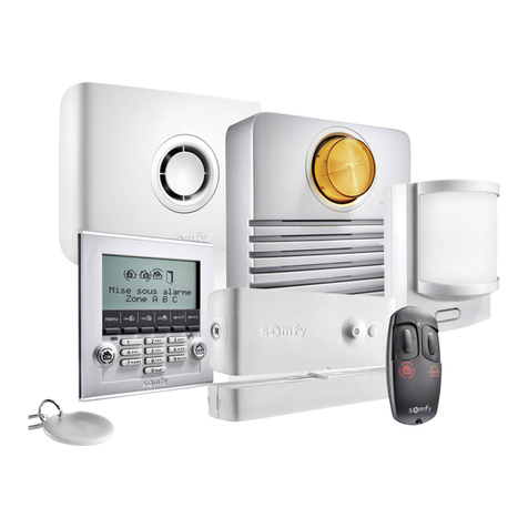
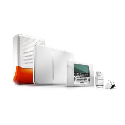
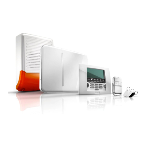
SOMFY Protexial User manual

P R O T E X I A L Wireless radio
alarm system
Installation manual

Welcome
Thank you for choosing a SOM Y alarm system.
Who is SOMFY?
SOM Y develops, manufactures and markets automatic devices for the openings in the home. Central alarm units, automatic devices
for blinds, shutters, garages and gates – all of SOM Y’s products meet your expectations in terms of day-to-day safety, comfort and
time-saving.
At SOM Y, the quest for quality is a continuous improvement process. It is thanks to the reliability of its products that SOM Y has
achieved such renown and become synonymous with innovation and technological expertise throughout the world.
This product complies with the requirements of European Standard EN 50130-4 and conforms to the essential requirements of
European R&TTE Directive 1999/5/CE. www.somfy.com/ce
Recommendations
1. Determine the location of the devices and the detection zones.
2. Insert the batteries into the devices.
3. Store the devices.
4. Fix to the wall, close the covers and test the devices.
5. Adjust the installation settings.
6. Test the installation.
We also strongly recommend that you:
■read this installation manual carefully and make absolutely sure that you follow all the mounting and operating
instructions
■keep this manual in a safe place. t could be useful if you decide to add devices to the installation.
If you need any advice concerning installation, contact.
Your installation may comprise a maximum of 50 devices (excluding automatic devices).
Do not clean the LCD keypad, the sirens and the central unit/phone dialer with alcohol.
Use a slightly damp cloth to clean the products.
Some recommendations and tips
To ensure the customer’s security, it is essential to ensure that they observe certain precautions:
■always activate the alarm system when absent
■lock all openings (doors, windows, etc.)
■never leave a remote control where it can be seen or easily identified
■never leave the keypad access code where it can be seen
■never leave a message on the telephone answering machine indicating that the house is empty.
■2■

Contents
■3■
How does the alarm system work?... ..................................................................................4
A completely upgradeable system.......................................................................................6
Recommendations..........................................................................................................7
Assigning a zone to the intrusion detectors ...........................................................................8
Installing the batteries ...................................................................................................10
Storing the devices.........................................................................................................11
Fixing the devices..........................................................................................................12
Fixing the sirens...........................................................................................................20
Fixing the central unit/phone dialer ...................................................................................21
PSTN module .............................................................................................22
GSM module..............................................................................................23
Making the system settings .............................................................................................28
Recording a customised alarm message announcement ..........................................................45
Testing the installation ..................................................................................................46
Remote settings via telephone..........................................................................................47
Viewing stored information when the orange indicator flashes on the LCD keypad ..........................47
Summary of system operation..........................................................................................48
Replacing the batteries ..................................................................................................50
Resetting the system ......................................................................................................51
If a remote control or badge is lost or stolen .......................................................51
If the installer code is lost..............................................................................51
Troubleshooting ...........................................................................................................52
Table of specifications....................................................................................................54
Index........................................................................................................................55

How does ...
Alarm system performance
Up to All the devices in the installation are battery powered.
Secure dual frequency radio technology
A patented, exclusive process: radio transmission is performed using two alternating frequencies which constantly take
over from one another to ensure that 100% of the information is transferred.
Regular system self-monitoring - Management of loss of radio link
The devices (with the exception of the remote controls) periodically send their operating status to the central unit: battery level,
door open, etc.
Tamper switch vandalism protection
If any of the devices in your installation are vandalised, the sirens are activated for 2 minutes and the phone dialer sends an
alarm message.
The central unit, sirens, phone dialer and keypads are protected by tamper switches if they are removed from the wall or their covers
are opened.
The detectors are protected if their front panel is opened.
For your convenience on installation, the tamper switches only work as of the first arming of the alarm.
AUTONOMY
YEARS
FREQUENCY
■4■

... the ala m system wo k?
Activation
The keypads, the remote controls and the badge make it possible to
control the system either on an individual zone basis or fully. They provide
a visual display of the status of the system during operation.
The LCD keypad allows for upgradeable, customised installation
(SMS function with phone dialer, etc.).
The LCD keypad and the multi-application remote control make it possible
to control the SOM Y automatic devices (motorised gate, garage door,
lighting or roller shutters with SOM Y motor).
It is also possible to control the alarm, roller shutters and lighting
remotely by phone.
ON/OFF +
ZONES REMOTE
CONTROL
MULTI-
APPLICATION
REMOTE CONTROL
ON/OFF REMOTE
CONTROL
BADGE
(SOLD IN PAIRS)
LCD KEYPAD
+ BADGE
CONTROL
KEYPAD
Dissuading, Alerting, Signalling
The increasing volume of the sirens discourages intruders.
The outdoor siren with flash alerts and signals an intrusion to anyone
nearby and the phone dialer sends one or more alarm messages.
The central unit/phone dialer analyses the information sent by the
detectors, triggers the sirens and sends one of the following to 4 telephone
numbers:
– either a synthesised voice alarm message, using the PSTN dialer module (Public Switched Telephone Network = the fixed
telephone line),
– or an alarm SMS, using the GSM dialer module (Global System for Mobile communications),
– or both, if your alarm unit is fitted with both a PSTN and a GSM module,
– or it sends an alarm to a remote monitoring centre, using the PSTN module.
If the installation has roller shutters (with a SOM Y motor), it is possible to program these to come down automatically when an
intrusion is detected or to go up automatically if smoke is detected, by means of a SOM Y receiver for roller shutters.
To further discourage intruders, it is also possible to control a light when intrusion is detected, using a SOM Y light receiver.
OUTDOOR SIREN
WITH FLASH
CENTRAL UNIT/PHONE
DIALER
INDOOR
SIREN
ntrusion detection
The movement detectors detect the movement of people or animals in
three-dimensional space.
The 2 pet movement detectors make it possible to protect a room
when a pet is present.
The opening detectors detect when a door or window is opened. They
can emit a chime on the indoor siren when such an action is detected
(see Kiela function on page 37).
The camera can be used to film a sequence linked to an intrusion.
Domestic fault detection
The domestic detectors detect the presence of water, smoke or a power
failure.
OUTDOOR
MOVEMENT
DETECTOR
MOVEMENT
DETECTOR
FOR BIG DOGS
GARAGE DOOR
OPENING DETECTOR
ROLLER SHUTTER
OPENING DETECTOR
AUDIOSONIC GLASS
BREAKAGE DETECTOR
OPENING AND GLASS
BREAKAGE DETECTOR
SMOKE
DETECTOR
DETECTOR
DETECTOR
POWER
DETECTOR
WATER LEAKAGE
DETECTOR
MOVEMENT
DETECTOR
■5■
IP CAMERA
MOVEMENT
DETECTOR FOR
SMALL PETS

A completely upg adeable system
Used to send
an alarm message
by GSM.
GSM dialer
module
In the case of multiple entrances. Control keypad
To extend intrusion
discouragement to another
part of the house.
ndoor siren
In the presence of a cat,
dog (less than 40 cm high)
or rodent.
Movement
detector for
small pets
You want to confirm that an
intrusion has taken place by
means of a sequence of photos or
remotely monitor your home.
Wi-Fi P camera
Used to send an alarm message
on the fixed telephone line
if the dwelling has one.
PSTN dialer
module
To control one or two Somfy
automatic devices (motorised
gate, garage door or lighting)
and your alarm from your car.
Multi-
application
remote control
To discourage intruders, alert
people nearby and indicate that
the system has been triggered.
Outdoor siren
with flash
You want to be alerted if
something is detected outside
your house. Using a Somfy
receiver, it is possible to close your
motorised Somfy roller shutters if
something is detected.
Outdoor
movement
detector
In the presence of a big dog
(more than 40 cm high).
Movement
detector
for big dogs
If the installation includes
roller shutters.
Roller shutter
opening
detector
For the system to trigger if
smoke is detected.
Thanks to a SOMFY receiver for
roller shutters, SOMFY motorised
roller shutters can be opened if
smoke is detected.
Smoke detector
To be alerted in the event of
power failure.
Power
detector
If the installation includes
a garage.
Garage door
opening
detector
If you have French windows or
bay windows.
Opening and
glass breakage
detector (white
or brown)
Audiosonic glass
breakage
detector
To be warned in the event
of flooding
(e.g.: washing machine).
Water leakage
detector
It is possible to extend the installation by adding remote controls, movement detectors, supplementary opening detectors (white or
brown) or the following specific devices:
■6■

Recommendations
Ensure good radio transmission
The correct propagation of radio waves depends on the nature of the material they travel through.
The range of the waves may vary depending on the type of construction (chalet, type of walls or partitions, apartment with metal
structure, etc.).
When a radio wave is unable to penetrate through a material, it is reflected. This impairs reception, in particular at the central unit.
It is often enough to move the central unit by just a few centimetres in order to avoid a zone without coverage.
Optimising radio range
■The central unit/phone dialer is the heart of the installation. Place it in a clear area in the centre of the home.
■Position the central unit/phone dialer devices more than 60 cm above ground level.
■To improve the propagation of the radio waves, make sure that the central unit is not:
- within one metre of an electrical fuse board or a cable bundle,
- close to an earth or metal plate,
- within one metre of sources of radio interference (such as a TV with surround HiFi).
■Avoid fixing detectors and keypads to metal sections or in confined areas.
■Fix sirens to clear areas and as high as possible.
■Before fixing the central unit/phone dialer, make sure that the various devices transmit properly. In the event of transmission
problems, move the central unit.
Ensuring the correct operation of the tamper switch system
or each of the products (central unit/phone dialer, siren or LCD keypad), choose a wall space with a good surface condition in order
to ensure the efficiency of the tamper switches (protection against vandalism).
mportant
To ensure that the system functions optimally, you are advised to choose the correct location for each device.
Plasterboard/Plaster/Wood
90 to 100%
Brick/Breeze block
65 to 95%
Reinforced concrete
10 to 70%
Metal
0 to 10%
■7■

Assigning a zone to the int usion detecto s
You can protect up to three areas of the home, referred to as zones.
A zone consists of intrusion detectors which are located in various parts of the home. The SOM Y system makes it possible to define
3 distinct zones. It is thus possible to arm the alarm in one zone only, in 2 zones or in all 3 zones (= full arming).
In the following example, the intrusion detectors in zone A monitor the front door and garage door while those in zones B and C
monitor different floors of the dwelling. All configurations are possible and depend on the nature of the dwelling and the use made
of the system by your customer.
Full arming (zones A + B + C)
Part or full arming
Part – 1 or 2 zones armed (A, B, C, A+B, A+C or B+C)
Independent ARM NG of the monitored zones, zone A, B or C.
Full – all 3 zones armed (A+B+C)
FULL arming of the alarm system: alarms are armed for the entire dwelling.
Zone A – Delayed triggering (AD) or immediate triggering (A)
of the alarm in the event of intrusion
■The dwelling’s access points (entry doors)
■A separate annex (the garage, for example)
Zone C – mmediate triggering of the alarm in the
event of intrusion
A part of the building that is unused during the day, a
storey or the basement
Zone B – mmediate triggering of the alarm in the event
of intrusion
A part of the building that is unused during the night, the
living room or all of the ground floor
■8■

Assigning a zone to the intrusion detectors
1/ Open the cover of the intru ion detector
(opening detector and movement detector )
2/ Determine the location of the device and
et up the zone for the detector
For each in rusion de ec or (movemen de ec ors and opening de ec ors), he
moni ored zone and riggering mode are defined using swi ches loca ed inside
hese produc s. They mus be configured when he corresponding device
is ins alled.
Movement detector are supplied se for zone C, immediate triggering.
Opening detector are supplied se for zone AD, triggering delayed by
45 seconds before ac iva ion of he alarm in order o allow sufficien ime o en er
and disarm he sys em if here is an opening de ec or posi ioned a he fron
door.
To cus omise his op ion, posi ion swi ches 1 and 2 as follows:
3/ Adju t the witche on the intru ion
detector to a ign them to a zone
Record he zone selec ion on he memo sheet in he opera ing manual.
Select
one – trigger mode
Position of
switches
What happens in the event of intrusion
(in part or full mode)
AD -
delayed
triggering
Ac iva ion of sirens is
delayed
(af er he en ry delay).
+
Telephone ransmission of one or more alarm
messages.
A - immediate triggering The indoor siren is ac iva ed immediately.
+
The ou door siren wi h flash is ac iva ed af er
10 seconds.
+
Telephone ransmission of one or more alarm
messages.
B - immediate triggering
C - immediate triggering
Do not touch the witche on the water leakage and power
detector .
LOCATION
OF SWITCHES
If the in tallation include the central
unit/phone dialer ver ion with Internet
acce , it i al o po ible to configure the
alarm y tem and a ign a zone to an
intru ion detector by computer ( ee the
upplementary manual).
In thi ca e, the zone etting
made by computer overrule the
witch etting made in ide the intru ion
detector .
■9■

Installing the batte ies
2/ nsert the batteries provided in all the devices
A beep sounds when the batteries are installed in the indoor siren and in the central unit/phone dialer, and the red indicator light
flashes on the central unit/phone dialer.
The siren may be triggered when the batteries are installed if you accidentally press the ON button on the remote control.
In this case, just disarm the alarm by pressing OFF on the remote control.
1/Open the covers of the other devices
Equipment needed to install the devices
Crosshead screwdriver, drill, hammer, pencil, ladder for outdoor siren.
9V
Pilealcaline
The batteries are already inserted in the remote controls.
Lithium battery
in the bag with the spacers.
Slide in the battery
with the +facing up.
CENTRAL UNIT/PHONE DIALER
CENTRAL UNIT/PHONE
DIALER
INDOOR SIREN
INDOOR SIREN
OUTDOOR SIREN WITH FLASH SMOKE DETECTOR
Do not close the covers straight away.
If the wall installation of the products has to be postponed, remove one battery from the products that are still open
to prevent them from draining.
Make sure that the batteries are inserted the right way
round (+/-).
Make sure that the ends of the batteries are touching the
battery contacts.

Sto ing the devices
■11 ■
1/ Activating the central unit/phone dialer storage mode
If you want to add devices when the central unit is already installed and the system is already operational, in order to avoid
opening the central unit/phone dialer, you can enter simplified storage mode by going to menu 753, (see page 38) or from
the bottom of the “Device list“ page via the alarm’s Internet interface. It only possible to enter storage mode when the system
is disarmed.
f you open the central unit/phone dialer, then you must deactivate the tamper switch by pressing OFF on the remote
control until the indicator goes off.
Press the button
briefly.
Press the button
briefly.
To open the memory, press the
PROG button; the red indicator
lights up.
Press OFF.
2/ Storing the devices
(in 2-minute storage mode, you have 2 minutes to store one or more devices)
Maximum of 50 devices per central unit/phone dialer.
A keypad A badge
A detector
An indoor siren
An outdoor siren with flash
A remote control
On the central unit/phone dialer
11Press the OFF button
once: BEEP!
Pass the badge in front of the LCD
keypad reception area: BEEP!
To store a 2nd badge, repeat the
same operation.
2
1
Press OFF.
1
...BEEP! on the central unit.
2
...BEEP! on the central unit.
2
2
1
Open the siren.
1
Open the siren.
1Press.
1
1
1
...BEEP! on the central unit.
3...BEEP! on the central unit.
3
...BEEP! on the central unit.
2
1
1
...BEEP! on the central unit.
22
DETECTOR FOR
SMALL PETS
ADDITIONAL LCD
KEYPAD
CONTROL
KEYPAD
You have 2 minutes to store one or more devices.
The 2-minute period is restarted as soon as a
device has been stored. The beep indicates that
the device has been stored in the central
unit/phone dialer.
After this 2- minute period, you must return to
storage mode by pressing the PROG button on the
central unit/phone dialer again.
During this 2-minute period (indicator lit), it is
not possible to test the installation.
...BEEP! on the outdoor siren.
4...BEEP! on the indoor siren.
4

Fixing the devices
■12 ■
Place the detector inside the dwelling on the upright of the opening part, either horizontally
or vertically, on the opening side (opposite the hinges).
The detector and its magnet-holder must be
perfectly aligned between the two markings.
Use one or more of the spacers supplied in
the packaging to adjust the magnet holder
and/or the detector.
It is also possible to raise the detector
by using 2 spacers fixed side-by-side
underneath it.
Place the central unit/phone dialer on a rigid surface, without securing it, at the centre of the dwelling close to a
telephone socket and the broadband router/modem in order to test for correct radio range following the installation
of each device.
Following installation of the devices, press the button on the front of the detectors. A BEEP will sound to confirm
correct radio range. f this is not the case, move the central unit/phone dialer until pressing the button on the front
of a detector triggers a BEEP. Then, and only then, it is essential that the central unit/phone dialer be mounted on
the wall.
Each product has a serial number on the self-adhesive label affixed to the product. Before performing any installation,
you must use this number to identify the detectors in your installation and note them on the memo sheet in the
operating manual.
If the gap between the opening part and the fixed part is too great, it is possible to
invert the 2 parts of the product.
Take the necessary precautions to avoid damage to the detector due to the door
being opened! This type of mounting is not recommended.
1
3Test the device:
Press the button on the
detector: BEEP!
or a period of 2 minutes, the indicator
on the detector lights up every time the
door is opened/closed.
Close the cover again.
2
Opening
detector
Please refer to the instructions supplied with the product.
Outdoor
movement
detector
Max. 10 mm
Alignment
Spacers
Spacers
MAGNET
DETECTOR
Ø 6 mm
To check for satisfactory radio range between the central unit/phone dialer and the devices:

Fixing the devices
The movement detectors are sensitive to heat: to avoid accidental triggering, never point a
movement detector directly towards a window, above or opposite a heat source (radiator,
convection heater or fireplace) or on a veranda.
The areas scanned by the movement
detectors should not intersect.
Operating
precautions
common
to the three
movement
detectors
90°
90°
1 2 3
To protect the greatest possible surface area, the detector can be placed in the corner of the room
2.30 m above the floor.
This type of detector is not recommended for garage use due to the presence of rodents, which
could cause accidental triggering. In this case, it is better to choose the movement detector for
small pets.
Movement
detector
31 Test the device:
or a 2-minute period, the
indicator on the detector lights
up every time something
moves in front of it.
Press the button on the
detector: BEEP!
Close the cover again.
2
Ø 6 mm
Avoid direct sunlight.
Avoid proximity to air
conditioning, heating, etc.
Avoid steam,
grease and humidity.
4 5
Avoid obstacles
which hide the
detection zone
(curtains,
windows, etc.)
Do not install outdoors.
This type of detector is intended to protect a room in the presence of a dog more than 40 cm high
that does not jump on furniture.
This type of detector is not recommended for garage use due to the presence of rodents, which
could cause accidental triggering. In this case, it is better to choose the movement detector for
small pets.
Movement
detector for
big dogs
110°
1 2
t should preferably be wall-
mounted at a height of 1.20 m
above the floor.
The rest of the installation and testing are
identical to those for the movement detector
(see above).
Ø 6 mm
TOP
BOTTOM
■13 ■

Fixing the devices
This detector makes it possible to detect the presence of any human in a room in the presence
of a small pet of a height less than 40 cm.
In the case of dogs taller than 40 cm, it is better to choose the movement detector for dwellings
with big dogs.
Movement
detector for
small pets
1 2
t should preferably be wall-
mounted at a height of between
2.10 and 2.40 m above the floor.
Do not lose the nut in the
bag containing the screw kit.
Do not lose the nut when opening the detector in order to change the
battery.
Do not close the detector again.
TEST mode is used to check the range of the detector.
The detector is positioned with its base on the wall but without being screwed on and
someone passes within the detector field.
Once the TEST has been successfully concluded, it is essential to set jumper 3 to the OFF
position in order to switch to operating mode.
In the case of medium-sized dogs, it is
better to mount the detector at a height of
2.40 m. Make sure that the detector is
mounted at least 80 cm above any piece of
furniture that a cat can climb on.
3
4
The detector has 3 jumpers:
Customising detector operation
2
1
1 ndicator light 2 Detection by
2 or 4 beams 3 TEST mode
ON With indicator light on the
front in the event of
detection.
This will affect the
duration of detector
battery operation.
Detection by 2beams
(most sensitive detection)
(the detector is supplied in
this mode).
Test mode: with indicator
light on each detection
(jumper 1 to ON).
OFF
Without indicator light in
the event of detection
(detector supplied in
this mode).
Detection by 4beams.
Recommended if several
pets are present.
Normal operating mode.
3
Position the nut in its housing and tighten
the locking screw.
Close the detector again. Tighten the screw at
the base of the detector.
2
DEFAULT POSITION OF THE JUMPERS
1
3
■14 ■

Fixing the devices
This detects the opening of a window, the vibration of the glass in the
event of attempted intrusion and the breakage of the glass.
The detector and its magnet are mounted in the same way as for the
opening detector (see page 12).
Use the double-sided adhesive strip to affix the glass breakage sensor
25 mm from the corner of the window. The window should be dry and
clean and preferably at a temperature of between 21 °C and 35 °C. Press
firmly on the glass breakage sensor to ensure that it is fixed properly.
Test of detector alone: see page 12.
Opening and glass
breakage detector
This detects the acoustic frequency of breaking glass and the difference in pressure between
the inside and outside of the dwelling. t only protects external windows.
It must be located at least 1.20 m from sources of acoustic interference (such as television set,
loudspeakers, drainpipes, doors, etc.).
Audiosonic
glass breakage
detector
Max. 6 m
from a window
Min. 1 m
from a window
Min.
3 m
Min. 3 m
Glass breakage will be detected in a radius of:
■6 m in the case of windows made of ordinary glass or double-glazing
(2.4 to 6 mm thick).
■3.65 m in the case of toughened or laminated glass (3.2 to 6.4 mm) or any
other type of glass.
Do not position the audiosonic detector on the same wall as the windows
that are to be protected.
1Mount the detector on the wall
approximately 2 m above the floor.
2Close the cover again.
DETECTOR
SENSOR
■15 ■

Fixing the devices
It is advisable to move the detector away to a wall using a 1 m cable in order to
avoid fixing it to the metal, which would impair the correct propagation of the
radio waves.
This is installed inside the shutter frame.
1Use at least 3 or 4 of the screws provided to fix the
square module flat in the centre of the frame in such
a way that the cord can travel freely with no risk of
shearing.
2The cord’s brass outlet cylinder must
be located as close as possible to the
opening in the frame in order to
avoid any risk of shearing.
3
4
The end of the cord
must be fixed by
means of a screw
passing through the
eyelet of the final
shutter strip.
ix the detector.
Roller shutter
opening detector
6Test the detector:
Press the button on the detector: BEEP!
or a 2-minute period, the indicator on the
detector lights up every time the roller shutter is
opened/closed.
Close the cover again.
5
DETECTOR
DETECTOR MODULE
MODULE
CORD
SQUARE
MODULE
BRASS
CYLINDER
Ø 6 mm
■16 ■

Fixing the devices
1Mount the protective sheath on the cable.
3 4 Connect the detector’s
2 stripped wires to the
electronic unit.
2ix the detector to the floor but avoid fixing it to any
metal sections.
ix the magnet to the garage door
between the two floor detector markings.
The type of fixing
will depend on the
floor material. Use different
screws if necessary.
K ≤25 mm
J ≤35 mm
Garage door
opening detector
MAGNET
MAGNETELECTRONIC UNIT
FLOOR DETECTOR
DETECTOR
ELECTRONIC UNIT
6
Test the electronic unit:
press the button on the
detector: BEEP!
or a 2-minute period, the indicator
lights up every time the garage door is
opened/closed.
Close the cover again.
5
ix the electronic unit to the wall
Ø
6 mm
■17 ■

Fixing the devices
1
2
Set the switches depending on the desired detector
triggering time:
ix the detector:
■On a wall close to a mains socket (230 V).
■As high as possible (for the correct propagation of
the radio waves) while taking account of the length
of the wire required for connection.
Make sure that you do not drill through any
electric wires in the wall.
Close the cover again and connect the mains adapter.
Power detector
Position of
switches
Triggering of the detector
after a maximum period of
5 minutes
10 minutes
15 minutes
20 minutes
ix the base to the ceiling.
1Close the detector again.
2
Do not install the detector:
■Within 1 m of heating, cooling or ventilation outlets. The smoke could be extracted
or diluted.
■In a room where there is a risk of condensation. Bathrooms and laundry rooms should
be avoided.
■Anywhere where smoke may be emitted (kitchen or poorly ventilated garage) and
generate unwanted alarms.
■In an excessively dusty or greasy location.
Smoke detector It is essential to fix the detector to the ceiling in the centre of the room and in all cases:
■more than 20 cm away from any obstacle (wall, partition, beam, etc.)
■more than 60 cm from the corner of the room
3Test the detector:
Press and hold down the button, a loud signal of 85 dB should be heard.
DETECTOR
Ø 6 mm
■18 ■

Fixing the devices
Water leakage
detector
1ix the sensor mount to the wall at floor level.
2Mount the detector casing on the wall approximately
1m above the floor.
3Slide the sensor between the mount’s lugs until you
hear a click, and pass the wire through the slots.
4Leave the detector’s switches in the O position.
Close the cover again.
5Test the detector:
Pour water between the sensor’s 2 electrodes.
The indoor siren sounds quietly for 2 minutes.
To stop the alarm, press the “O “ button on the remote control.
At the end of the test, remove the water and dry the electrodes.
DETECTOR
MOUNT
SENSOR
f you want to control a motorised garage door or gate, it is essential to install
the keypad where you can see these automatic devices for safety reasons.
2
LCD keypad This must be inside the dwelling. It is advisable to install it near the front door.
70 mm
BOTTOM
TOPTOP
60
BOTTOM
1Close
the product
again.
Affix the tamper strip firmly against the wall.
HOLE IN
TAMPER STRIP
Ø 6 mm
2
Control keypad This must be inside the dwelling. It is advisable to install it near the front door or inside
the garage.
51 mm
HAUTHAUT TOPTOP
47
BASBAS DOWNDOWN
1Close the
product
again.
Tighten the 2 screws
on the sides.
Tighten
the 2 screws
at the base of
the casing.
Affix the tamper strip firmly against the wall.
HOLE IN
TAMPER STRIP
Ø 6 mm
■19 ■

Every time the alarm is armed or disarmed, the indoor siren emits one or more beeps to indicate that the instruction has been
received successfully.
Before closing the product again, you can cancel the beeps on the indoor siren:
Fixing the si ens
■20 ■
ndoor siren This should preferably be installed
in the centre of the dwelling to
ensure better sound propagation.
It should be at a high level where
it is difficult to access (e.g.: in the
stairwell, on top of a wardrobe).
1
2
To cancel the BEEPs!
Press the button on the siren for approximately 5 seconds
until the indicator goes off.
To restore the BEEPs!
Press the button on the siren for approximately 5 seconds
until the indicator goes off.
You will hear a BEEP!
To be better informed of the functioning of your system, we recommend that you leave the
beeps active on at least one device.
... 5 s ... 5 s, BEEP!
Outdoor siren
with flash The outdoor siren with flash is protected against running water, condensation
and humidity provided that it is mounted the right way up (flash upwards).
To ensure optimum battery life, it is advisable to install it sheltered from
sunlight and water.
1During wall installation, suspend the top
of the cover on the bottom of the base.
Before closing the outdoor
siren with flash again, you can
cancel its beeps (see boxed text 2,
indoor siren, above).
3
Close the cover again.
4
Close the cover again.
3
Ø 6 mm
nsert the batteries,
making sure they are
the right way round (+/-).
2
Remove the batteries before installation.
Table of contents
Other SOMFY Security System manuals

SOMFY
SOMFY PROTEXIOM GSM Installation guide

SOMFY
SOMFY HOME ALARM ADVANCED User manual

SOMFY
SOMFY TaHoma Serenity User manual

SOMFY
SOMFY 2401453 User manual

SOMFY
SOMFY Home Keeper User manual

SOMFY
SOMFY Home Alarm User manual

SOMFY
SOMFY One User manual

SOMFY
SOMFY Home Alarm User manual

SOMFY
SOMFY 2401491 User manual

SOMFY
SOMFY Outdoor camera User manual

SOMFY
SOMFY Home Alarm Essential User manual

SOMFY
SOMFY Home Alarm User manual

SOMFY
SOMFY HOME ALARM ADVANCED User manual

SOMFY
SOMFY Home KEEPER Series User manual

SOMFY
SOMFY One+ User manual

SOMFY
SOMFY Home Keeper User manual

SOMFY
SOMFY Home Alarm User manual

SOMFY
SOMFY One User manual

SOMFY
SOMFY 5013494 User manual