Spectra DG613 User manual


SF803
DG613/DG613G
DG813
RC803
2
ST802

TABLE OF CONTENTS
Introduction
For Your Safety
Laser
How to Use the Laser System
Powering the Laser
Turning On/Off the laser
Features and Functions
Laser Setup
Turning On/Off the laser
Standard Display Laser and RC803
RC803 Radio/IR Remote Control
Powering the RC803
Turning On/Off the Radio/IR Remote Control
Pairing the RC803 with the DG813/DG613/DG613G
Components SpotFinder SF803
Powering the SF803
SF803 - Features and Functions
Pairing the Spot Finder SF803 with the DG813
Turning On/Off the Transporter ST802
Pairing the ST802 with the DG813/DG613/DG613G
Menu Functions
Entering Grade
Automatic Spot Align (DG813)
Automatic Spot Match (DG813)
Automatic SpotLok (DG813)
Manual Spot Search (DG813)
Line Scan
Line Set/Check
Start Reference Check
Standby Mode 3

Settings
Info
Service
Setting menu details
Grade Entry
Grade Display
Sensitivity Selection
User Name
Set Password
Password On/Off
Radio Channel
Select Language
Position Info
Calibration
PROTECTING THE UNIT
CLEANING AND MAINTENANCE
PROTECTING THE ENVIRONMENT
TECHNICAL DATA
DECLARATION OF CONFORMITY
4

Introduction
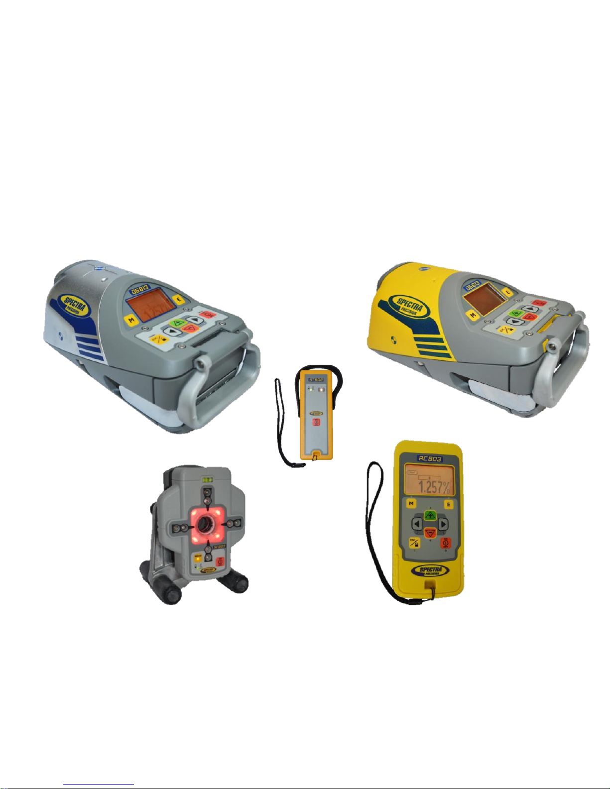
Thank you for choosing one of the Spectra Precision Lasers from the Trimble family of precision pipe lasers.
The pipe laser is an easy-to-use tool that provides underground contractors line, elevation, and grade control
for installing storm, sanitary, or other gravity-flow pipe. This system can also be used for tunneling, boring, pipe
alignment, or any other application requiring line, elevation, and grade control.
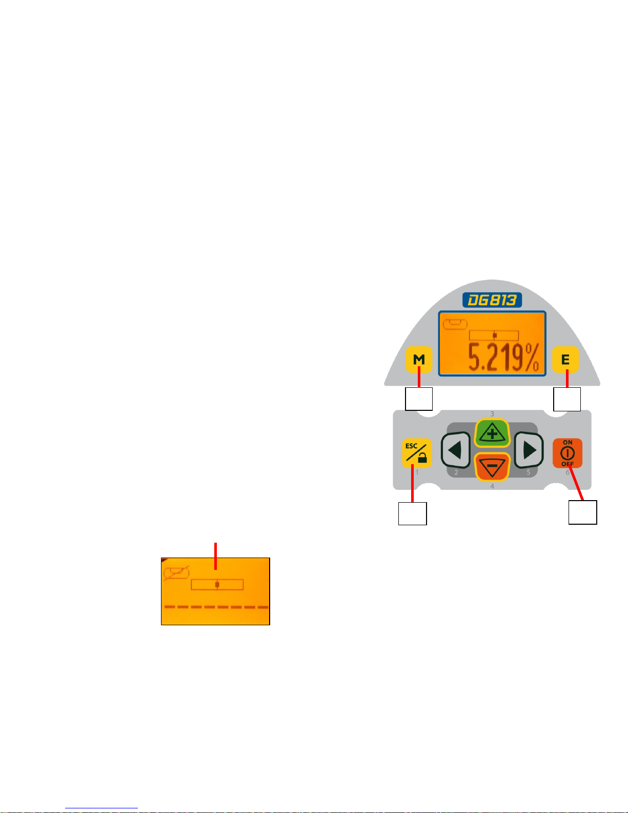
The pipe laser projects a highly visible laser beam in a direction at a predetermined (grade) for the
alignment of gravity-flow pipe. The laser light is intercepted by a target. To align the pipe, you need to
position it so that the pipe laser’s beam is centered at the target’s bullseye.
For Your Safety
For hazardless and safe operation, read all the user guide instructions.
-Use of this product by people other than those trained on this product may result in exposure to
hazardous laser light.
- Do not remove warning labels from the unit.
- The DG813/DG613/DG613G are class 3A/3R laser (<5mW; 600 –680nm) IEC 60825-1:2014). Class 2
version are also available.
-Never look into the laser beam or direct it to the eyes of other people.
- Always operate the unit in a way that prevents the beam from getting into people's eyes.
-If initial service is required, which results in the removal of the outer protective cover, removal
must only be performed by factory-trained personnel.
Caution: Use of other than the described user and calibration tools or other procedures
may result in exposure to hazardous laser light.
Caution: Using different than described at the pipe laser user guide, may result in unsafe
operation. 5

Features and Functions
Laser
1 Battery Compartment
2 Battery Door Latches
3 LCD Graphic Display
4 GradeAxis Pivot Marker
5 Line-Axis Pivot Marker and LED
6 Handle
7 Axis Alignment Markers
8 Mounts for scope adapter
9 5/8”-11 Threaded Mount
10 Remote Receiver Window
11 Beam-Exit Window
6
12 Power Button
13 M - Menu Button
14 E - Enter Button
15 Escape/Lock Button
16 Left Line Control Button
17 Plus Button
18 Minus Button
19 Right Line Control Button
How to Use the Laser System
Batteries
WARNING
Ni-MH batteries may contain small amounts of harmful substances.
Be sure to charge the battery before using it for the first time, and after not using it for an extended length of
time.
Charge only with specified chargers according to device manufacturer‘s instructions.
Do not open the battery, dispose of in fire or short circuit; it may ignite, explode, leak or get hot causing
personal injury.
Dispose in accordance with all applicable federal, state, and local regulations.
Keep the battery away from children. If swallowed, do not induce vomiting. Seek medical attention
immediately.

Powering the Laser
Recharging the Batteries
The laser is shipped with a rechargeable Ni-MH battery pack, it is keyed to prevent mis-insertion.
Note: The approximate charge of the batteries is shown at the top of the LCD when pressing the E button.
The charger requires approx. 10 hours to charge completely discharged batteries.
For charging, connect the plug of the charger to the recharge jack of the battery pack.
New or long-time out-of-use rechargeable batteries reach their best performance after being charged and
recharged five times.Alkaline batteries can be used as a backup. Insert 4 D-cell batteries noting the plus (+)
and minus (-) diagrams inside the battery housing.
The batteries should only be charged when the laser is between 50°F and 104°F (10°C to
40°C). Charging at a higher temperature may damage the batteries. Charging at a lower
temperature may increase the charge time and decrease the charge capacity, resulting in
loss of performance and shortened life expectancy.
Installing Batteries
Open the battery door by pulling out the door latches. Insert batteries (or a rechargeable battery pack) into the
housing so that the negative poles are on the bigger battery spiral springs.
Close the battery door and lock it by pushing the door latches back to the housing.
Only the original rechargeable battery pack allows charging with the provided charger.
7

Features and Functions
1. Battery Compartment –holds the
NiMH battery pack. (D-Cell alkaline batteries
can be used as a backup.)
2. Battery Door Latches –
locks/unlocks and holds the battery
compartment in place.
3. LCD Graphic Display - shows the
power, grade, battery, out-of-level, beam
position and status of the laser.
4. Grade Axis Pivot Marker - identifies
the pivot point for the grade
system
5. Line-Axis Pivot Marker and LED –
used to align a transit over the top of the
laser; lights for 15 minutes after turning on
the laser or pressing one of the buttons.
6. Handle - to carry the laser easily
and to attach a safety rope in manholes
with water.
1
432
5
6
8

7. Axis Alignment Markers - used to align
the laser when the line system is centered.
8. Mounts for scope adapter –to
attach the optional scope adapter for the
„Over the Top“ application
9. 5/8”-11 Threaded Mount –to attach the laser
to various setup accessories
10. Remote Receiver Window –
receives signals from the RC803 and SF803
11. Beam-Exit Window –provides a
clear window for the laser beam to exit
the pipe laser.
Features and Functions
10
11
7
9
8
9

Features and Functions
12. Power Button - turns the laser On/Off
(To turn off the laser, press and hold the button
for 2 seconds).
13. M –Menu Button - Quickly press and release
starts the menu entry. Use the 2 to 5
buttons to toggle through the menu.
14. E - Enter Button - Quickly press and release
to activate a selected menu function and show the
actual laser and remote control battery status.
15. Escape/Lock (ESC) Button - (If pressed
simultaneously with one of the left/right or +/-
buttons, it locks/unlocks the +/- or the left/right
buttons, so that the unit can’t be unintentionally
changed. If pressed for 5 seconds, the unit
switches to the manual mode (steep grade).
13 14
15 12
10

Features and Functions
16. Left Line Control Button - moves the laser
beam to the left. (Simultaneously pressed with the
Right Line Button, centers the line.)
17. Plus Button - increases the grade.
18. Minus Button - decreases the grade.
19. Right Line Control Button - moves the laser
beam to the right. (Simultaneously pressed with the
Left Line Button, centers the line.)
16 17 18 19
11

Laser Setup
Position the laser at the manhole invert or on bottom of the trench at the desired elevation.
Turning On/Off the laser
Press the power button to turn On the laser; the LCD shows Initialization for one second (red and green
LEDs are on - diagnostic mode).
The unit starts the temperature/reference check while the thermometer/CAL symbol is flashing.
Don‘t start automatic functions at the menu before the reference check has been finished.
If an automatic function will be selected and then confirmed with the E button during the reference
check, the display shows the reference check is still running.
The standard display turns on and the self-leveling will start at once.
The unit is leveled when the laser beam is no longer flashing (once every second).
To turn Off the laser, press and hold the power button for two seconds.
If the laser is positioned beyond its self-leveling range of -12 to + 40%, the laser beam remains flashing.
Reposition the laser within its self-leveling range. The laser’s cross axis is completely compensated over
the entire roll range (+/- 15°). Once leveled, the unit constantly monitors its level condition. Depending on
the selection at settings, the setup control (Line alert) is activated 5 minutes or 30 seconds after self-
leveling was performed. If Line Alert condition comes Off, the beam (+LEDs) flashes
two times, pauses for 2 seconds and flashes again two times.After deleting the
Line Alert by pressing the Ebutton, check the beam’s correct position using the target
at the last pipe which was led before the Line alert came off. 12
12

Features and Functions
Standard Display Laser and RC803
The remote control mirrors the functionality of the pipe laser keypad
9
13
Automatic mode Beam line position related to the housing
+/- buttons locked actual grade value
line buttons locked
Beam position at SF803
1 - Escape/Lock Button
2 - Left Line Control Button
3 - Plus Button
4 - Minus Button
5 - Right Line Control Button
6 - Power Button
M - Menu Button
E - Enter Button
Hole for hand loop

RC803 Radio/IR Remote Control
Powering the RC803
1. Open the battery door using a coin or similar pry
device to release the battery door tab on the RC803.
RC803 will be shipped with alkaline batteries
Rechargeable batteries can be used optional but need
to be charged externally
2. Insert two AA batteries noting the plus (+) and minus (-)
diagrams inside the battery housing.
3. Close the battery door. Push down until it “clicks”
into the locked position.
Turning On/Off the Radio/IR Remote Control
The Radio/IR remote control is a hand-held device that allows you to send operational commands to the laser from a
remote location.
Press the power button to turn on the radio/IR remote control.
If the RC803 is outside the radio operating range the remote switches automatically into the IR connection capability.
Note: When the remote control is initially turned on, the standard display (model number and software version) appear
for the first 3 seconds, then the grade value and line direction indications briefly appear in the LCD.
With every button press, the LCD backlight is activated and turns off automatically if no button is pressed for 8
seconds.
To turn off the radio remote control, press and hold the power button for two seconds.
Note: 5 minutes after the last button press, the remote control turns off automatically.
Pairing the RC803 with the DG813/DG613/DG613G - First, make sure the transmitter and the remote control
are turned off. Then press and hold the Escape/Lock (ESC) button and turn on the transmitter. During the next 6
seconds (the red LED flashes fast while the display shows Pairing) repeat the same steps on the remote control.
The remote’s display show Pairing OK for one second and then the same function as the laser is actually working to
indicate the transmitter has been matched with the remote control. 14

Components Spot Finder SF803
15
1 - SF803
2 - Target Plate
for Spot Finder
3 - Center Hole
4 - Power Button
5 -Bubble Vial
6 - Battery LED
7 - Mode LED
8 - Red Direction LEDs
9 - IR transmitters/receivers
10 - Marking notches (front and back)
11 - M6 Clamp Mount
12 - Battery door
13 - Latch for Battery Door
14 - Release Tab Target Plate
15 –SF803-Poladapter
2
14
11
1312
10
1
4
7 3
6
5
9
10
10
10
8
5
15

Powering the SF803
1. Open the battery door pulling the battery door latch.
The SF803 will be shipped with alkaline batteries.
Rechargeable batteries can be used optional but need to be charged externally
2. Insert four AA batteries noting the plus (+) and minus (-) diagrams inside on the battery door.
3. Close the battery door. Push down until it “clicks” into the locked position.
SF803 - Features and Functions
1. Power Button:
Press and release the power button to turn ON the SF803.
All display LED’s will light for 1.0 sec.
Press and hold power button for >2 sec. to turn OFF the SF803.
LED’s:
2. LED1:
solid green when SF803 is on and battery OK
blinking red if battery voltage is 3,8V<V bat <4V
solid red if battery voltage is <3,8V; SF803 turns off automatically after 5 min.
3. Mode LED2:
yellow solid: radio connection OK / yellow flashing: none or lost radio signal
4. Direction LEDs red:
Manual mode: pointing towards the center of the plumb beam.
All 4 LEDs are solid red when the beam is centered.
Automatic SpotLok mode: LEDs solid for 5 min., then flashing every 5 seconds.
Pairing the Spot Finder SF803 with the DG813 -
First, make sure the transmitter and the Spot Finder are turned off. Then press and hold the Escape/Lock button
and turn on the transmitter. Turn On the Spot Finder; the SF803 pairs now automatically with the transmitter.
After a successful pairing, the Laser shows the standard display while the yellow SF803 LED is solid. 16
1
2
3
4

ST802 Transporter
The Transporter is a hand-held device that extends the radio operating range between the RC803 and the DG813
(standard) and DG613/DG613G (optional).
Powering the ST802
1. Open the battery door using a coin or similar pry
device to release the battery door tab on the ST802.
ST802 will be shipped with alkaline batteries
Rechargeable batteries can be used optional but need
to be charged externally
2. Insert two AA batteries noting the plus (+) and minus (-)
diagrams inside the battery housing.
3. Close the battery door. Push down until it “clicks”
into the locked position.
Turning On/Off the Transporter
Press the power button to turn on the Transporter.
Note: When the Transporter is initially turned on, both LEDs turn on for one second (left LED red, right LED yellow –
diagnostic mode).
To turn off the Transporter, press and hold the power button for >2 seconds.
LED’s:
Left LED:
solid green when ST802 is on and battery OK
blinking red if battery voltage is >2V and <=2,4V
solid red if battery voltage is <=2V; ST802 turns off automatically after 5 min.
Right LED:
yellow solid: radio connection OK / yellow flashing: none or lost radio signal
Pairing the Transporter ST802 with the DG813 /DG613/DG613G
First, make sure the transmitter and the Transporter are turned off. Then press and hold the Escape/Lock button and
turn on the transmitter. Turn On the Transporter; the ST802 pairs now automatically with the transmitter.
After a successful pairing, the Laser shows the standard display while the yellow ST802 LED is solid. 17

Transporter ST802 –DG applications
DG813/613/613G at the manhole => ST802 => RC803
ST802 offers radio connection between RC803 and DG813/613/613G also inside the open trench at the
end of the pipe.
DG813/613/613G at the tripod => ST802 => RC803
ST802 extends the radio operating range between DG813/613/613G and RC803 working at „Over the Top“
applications
up to 100 m /330 ft
>0.50 m
>2 ft
up to 140 m/460 ft up to 120 m/400 ft
>0.50 m
>2 ft

19
Menu Functions
Press and release M button at the Standard Display to enter the MENU.
The menu offers always only the available features depending which pipe laser (DG813 or
DG613/DG613G) is used.
The icon of the selected function will be highlighted.
A down arrow at the the right site indicates that the user can scroll down through the menu using the down
arrow button.
After going to the next menu row, an up/down arrow at the the right site indicates that the user can scroll
up/down through the menu using the +/- arrows buttons.
Pressing and releasing button M changes the unit always back to the standard or previous display.
Press and release the 2 to 5 buttons until the desired function at the selected menu row is marked.
Press and release button E to open the submenu OR start the selected function.
Menu functions available at the DG813
Menu functions available at the DG613/DG613G

20
Menu Functions (IR controlled)
If the RC803 is paired with a transmitter and the radio connection doesn’t work, e.g., through a pipe, the IR
connection offers the following functions.
Press and release the Mbutton at the Standard Display.
Pressing and releasing button Mchanges the unit always back to the standard or previous display.
Press and release the buttons 2 to 5 until the desired icon is highlighted.
Press and release E button start the selected function.
Note: If a remote is paired with a transmitter the IR signals of the remote (in case of an interrupted radio
connection) will be transmitted in a private mode so that only the paired transmitter can receive these IR
commands.
IR-menu functions available at the DG813
IR-menu functions available at the DG613/DG613G
This manual suits for next models
2
Table of contents
Other Spectra Measuring Instrument manuals

Spectra
Spectra GL1425C User manual

Spectra
Spectra V610 User manual

Spectra
Spectra HV301 User manual

Spectra
Spectra Trimble hl750 User manual

Spectra
Spectra MKS Cirrus LM99 User manual

Spectra
Spectra HL450 User manual

Spectra
Spectra Trimble hl750 User manual

Spectra
Spectra MKS-11 User manual

Spectra
Spectra Precision HD150 User manual