Speedsignal B-339MZ01 User manual

Carl-von-Ossietzky Straße 3 + 7 Fax: +49 8061 49518 – 10 Homepage: www.speedsignal.de
D- 83043 Bad Aibling facebook: facebook.com/speedsignal
Nur für Fahrzeuge mit Automatikgetriebe
Only for vehicles with automatic gearbox
Fahrzeuge
– Vehicles
Mazda
Mazda 6 GJ FL
EINBAUANLEITUNG
Installation Guide
RunLock MWS)
RunLock
RunLock für Mazda
Universal RunLock for all vehicle types
Art. Nr. B-339MZ01
10R - 055004
B-339MZ01_R0.docx 15.09.2023 Seite 2 von 10
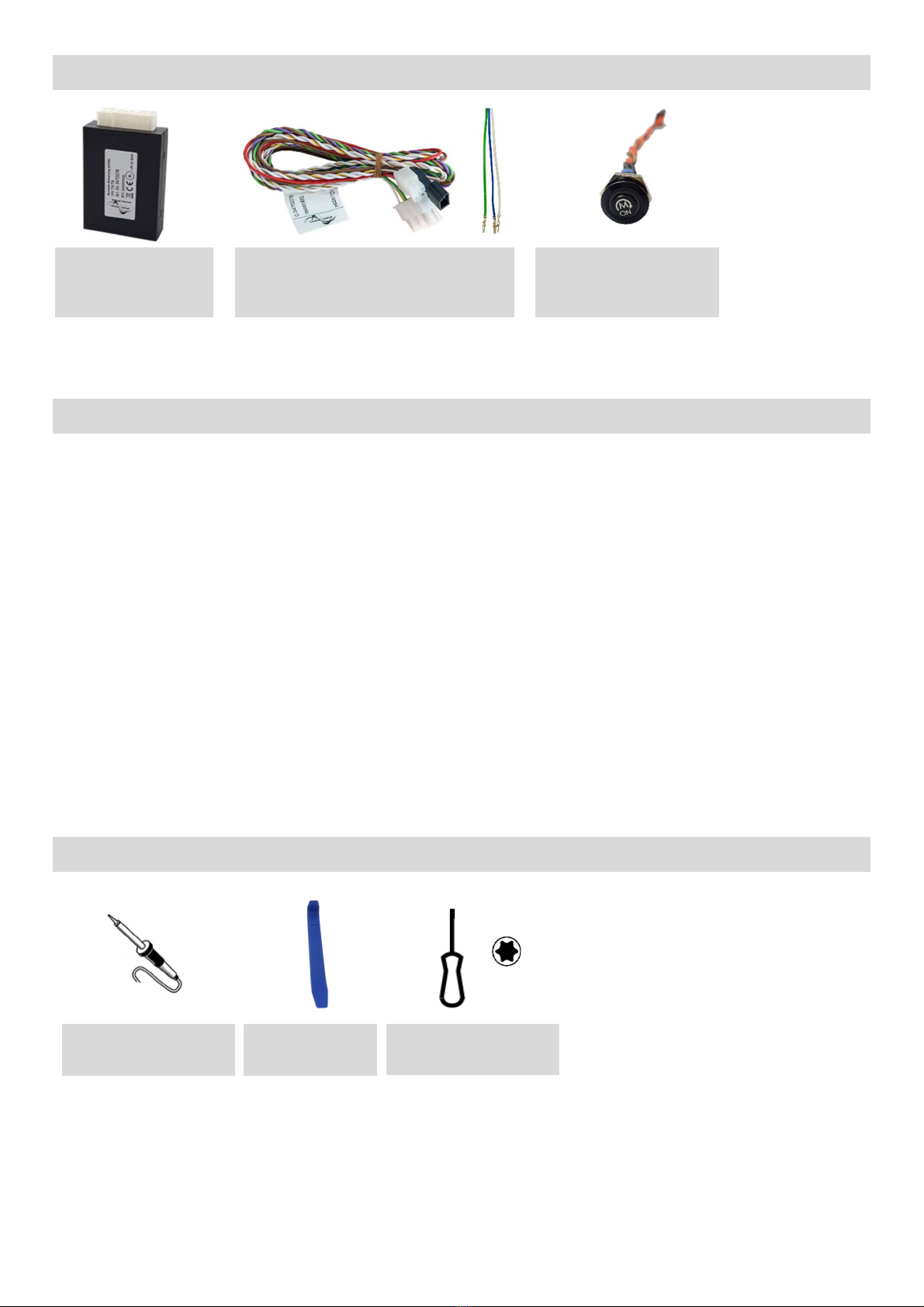
Lieferumfang
– Scope of delivery
Beschreibung
- Description
Die Motorweiterlaufschaltung ermöglicht einen ge icherten Motorweiterlauf bei Verla en de Fahrzeug mit dem
Fahrzeug chlü el. Durch die Möglichkeit, da Fahrzeug bei laufendem Motor von außen zu verriegeln, wird eine
Fremdnutzung au ge chlo en.
Die Motorweiterlauf chaltung i t in er ter Linie für Behördenfahrzeuge in Au übung ihrer dien tlichen Pflicht vorge e-
hen. Beim Einbau in andere Fahrzeuge al Behördenfahrzeuge wei en wir darauf hin, da ein unnötige Laufenla en
von Fahrzeugmotoren nach §30 I StVO verboten i t.
The RunLock enable the engine to be run on ecurely while leaving the vehicle with the vehicle key. The option of locking the
vehicle from the out ide while the engine i running prevent the vehicle from being u ed by third partie .
Primarily it i intended for the u e within authority vehicle in exerci e of their dutie .
For the in tallation into other vehicle (not authority) we point out that an unnece ary engine run i forbidden by law in many
countrie uch a in Germany according to StVO §30.
Benötigtes Werkzeug
- Required tools
Lötkolben
Soldering iron
Interface RunLock
Interface RunLock
3470040
Kabel atz RunLock univer al
Cable harne RunLock univer al
C-3470078
RunLock Ta ter
RunLock Button
6003131
Au bauwerkzeug
Removal tool
Torx Schraubenzieher
Torx crewdriver

B-339MZ01_R0.docx 15.09.2023 Seite 3 von 10
Abgriffpunkte
– Tap points
A:
CAN Bus
Abgriff an OBD
CAN bu tap at gateway
C:
Abgriff Lock/Unlock am RBCM
CAN bu tap at gateway
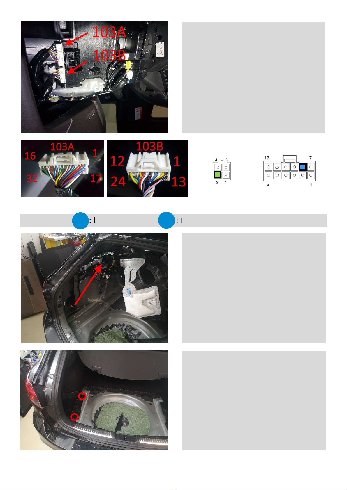
B: Abgriff Start
-
Stop
-
Deaktivierung
CAN bu tap at gateway
A
B
C
B-339MZ01_R0.docx 15.09.2023 Seite 4 von 10
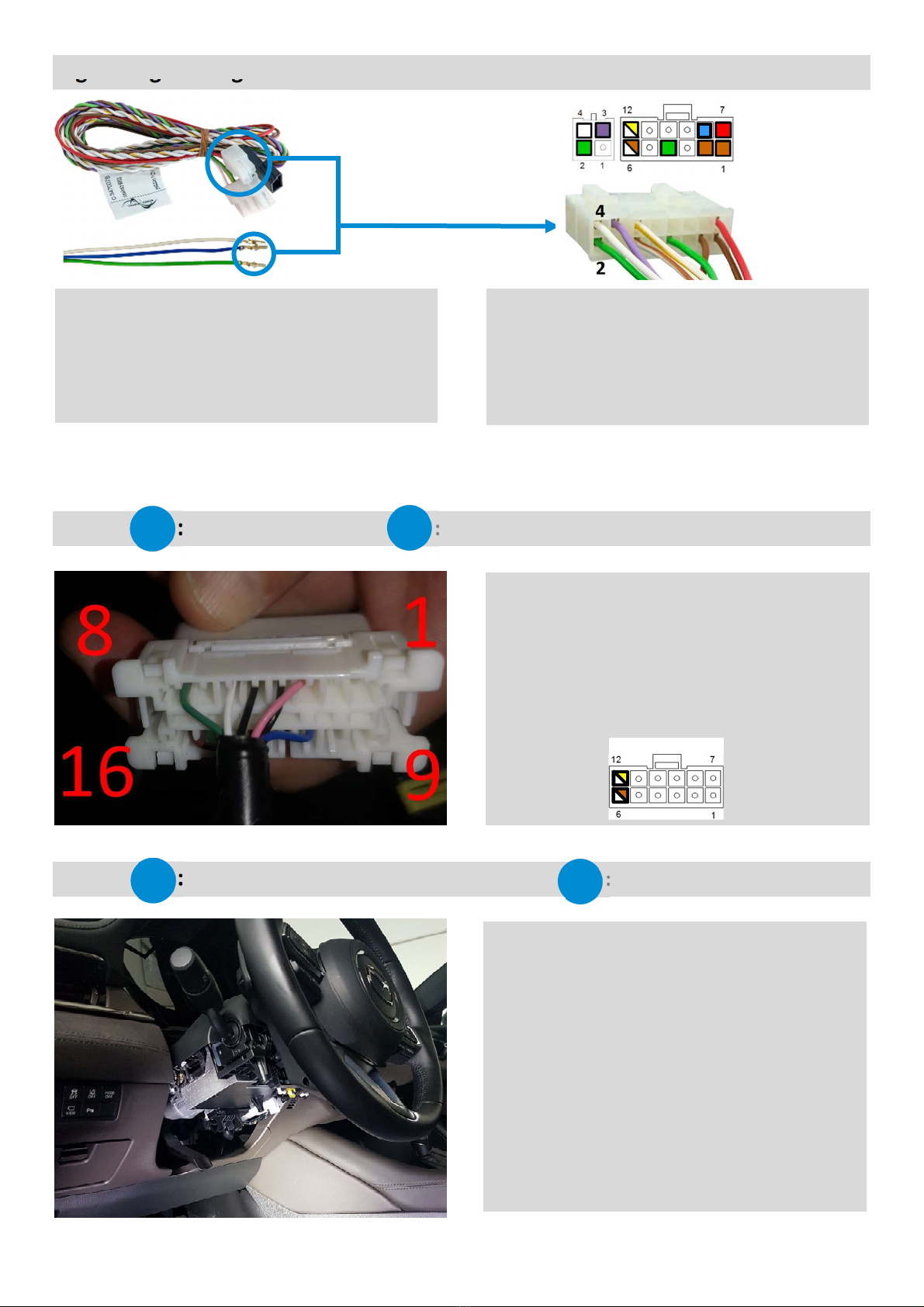
Ergänzungsleitungen einpinnen
– Pinning in additional cables
Abgriff : CAN-Bus
– Tap point : CAN bus
Abgriff : Start-Stop Deaktivierung
– Tap point : start-stop deactivation
A
A
Die OBD-Buch e befindet ich im Fahrerfußraum link
oben. PIN 6 (weiß) mit gelb-weißer Leitung de Kabel-
baum verbinden (CAN High). Pin 14 (rot) mit braun-
weißer Leitung de Kabelbaum verbinden.
The OBD ocket i located in the driver' footwell at the
top left. Connect PIN 6 (white) with yellow-white wire of
the wiring harne (CAN High). Connect pin 14 (red) with
brown-white wire of the wiring harne .
Belegung Interface
B
B
Die Start-Stop-Einheit befindet ich an der Lenk äule. Im
er ten Schritt mu die untere Abdeckung der Lenk äule
( iehe neben tehende Abb.) demontiert werden
The tart- top unit i located on the teering column. In
the fir t tep, the lower cover of the teering column
( ee adjacent picture) mu t be di mantled.
Dem mitgelieferten Kabel atz C-3470078 liegen drei Er-
gänzung leitungen bei.
Weiße Leitung auf Pin 4 de 4-poligen Microfit-Stecker
Grüne Leitung auf Pin 2 de 4-poligen Microfit-Stecker
Blaue Leitung auf Pin 8 de 12-poligen Microfit-Stecker
Three upplementary wire are included with the up-
plied C-3470078 cable harne .
White wire to pin 4 of the 4-pin Microfit connector.
Green wire on pin 2 of the 4-pin Microfit connector.
Blue line on pin 8 of the 12-pin Microfit connector
B-339MZ01_R0.docx 15.09.2023 Seite 5 von 10
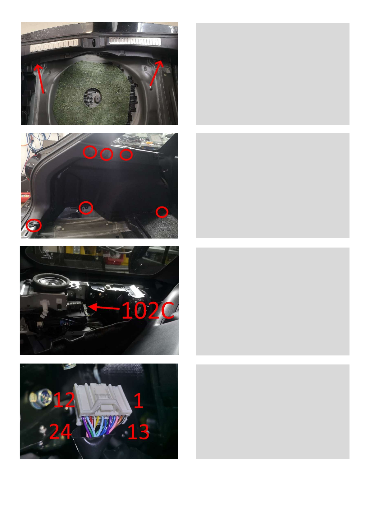
Abgriffpunkt : RBCM
– Tap point : RBCM
32-pol Stecker 103A ab tecken und PIN 20 (grün) tech-
ni ch einwandfrei mit der blauen Leitung de mitgelie-
ferten Kabel atze verbinden (PIN 12.8)
Im näch ten Schritt an 24 poligen Stecker 103B da Kabel
an PIN 17 (rot) mit der grünen Leitung de mitgelieferten
Kabel atze techni ch einwandfrei verbinden (PIN 4.2)
Di connect 32-pin connector 103A and connect PIN 20
(green) technically correct with the blue line of the up-
plied cable et (PIN 12.8)
In the next tep, connect the cable at PIN 17 (red) of the
24-pin connector 103B with the green cable of the up-
plied cable et (PIN 4.2)
Belegung Interface
C
C
Da RBCM befindet ich an der gezeigten Po ition im
Kofferraum. Um da RBCM zu erreichen, die linke Seiten-
verkleidung im Kofferraum lö en. Die er Vorgang wird
im Weiteren genauer erklärt.
The RBCM i located in the po ition hown in the trunk.
To acce the RBCM, loo en the left ide panel in the
trunk.
Die Befe tigung an den markierten Stellen entfernen und
die linke Ablagefläche au bauen.
Take out the trunk floor cover and remove the clip at
the marked point . Now the cover for the di charge pro-
tection can be di mantled.
B-339MZ01_R0.docx 15.09.2023 Seite 6 von 10
Die Kofferraumbodenabdeckung herau nehmen und die
Clip an den markierten Stellen entfernen. Jetzt kann die
Abdeckung für den Entlade chutz demontiert werden.
Take out the trunk floor cover and remove the clip at
the marked point . Now the cover for the di charge pro-
tection can be di mantled.
Die Schrauben / Clip an den markierten Po itionen ent-
fernen und die eitliche Kofferraumabdeckung lö en.
Remove the crew / clip at the marked po ition and
loo en the ide trunk cover.
Der Stecker 102C am RBCM befindet ich an der gezeig-
ten Stelle.
Connector 102C on the RBCM i in the location hown.
Da weiße lo e Kabel vom mitgelieferten Kabel atz
(PIN4.4) ent prechend verlängern und mit dem 24 pol
Stecker 102C PIN 16 (weiß- chwarz) techni ch einwand-
frei verbinden.
Extend the white loo e cable from the upplied cable et
(PIN4.4) accordingly and connect it to the 24-pin con-
nector 102C PIN 16 (white-black) in a technically flawle
manner.

B-339MZ01_R0.docx 15.09.2023 Seite 7 von 10
+12 V Spannungsversorgung
– Plus and minus supply
An geeigneter Stelle am Fahrzeug Ma e (PIN 1 am Interface) und Stromver orgung
(PIN 7 am Interface) abgreifen.
Die maximale Stromaufnahme de Interface beträgt 1 Ampere!
At a uitable location on the vehicle, tap the ground (PIN 1 on the interface) and power
upply (PIN 7 on the interface).
The maximum current con umption of the interface i 1 ampere!
Belegung Interface
7
1
Zusammenbau
der
Verkleidungen
–
Reassembling covers
Nach erfolgtem Funktion te t alle Verkleidungen und Abdeckungen in der rückwärtigen Reihenfolge
w
ieder
zu-
ammenbauen.
After the function te t ha been completed, rea emble all panel and cover in the rever e order.
B-339MZ01_R0.docx 15.09.2023 Seite 8 von 10
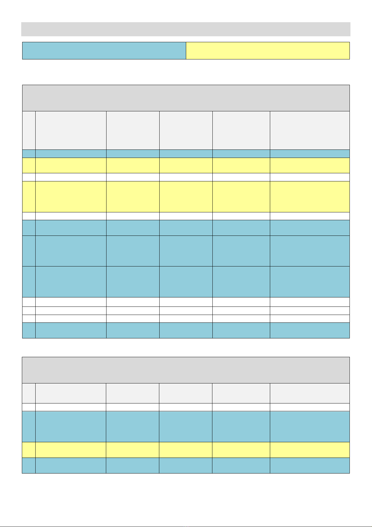
Pin Belegung Kabelsatz Stecker
– Pin Assignment Cable harness connector
blau = Verbindung zum Fahrzeug
blue = connection to vehicle
gelb = Verbindung zum Taster
yellow = connection to button
Anschlussbelegung 4-poliger Minifit-Stecker
Pin assignment 4-pin Minifit connector
Ein-/Ausgang
Input/output
Bezeichnung
designation
Kabelfarbe am
Interface
Kabelfarbe am
Fahrzeug
Bemerkung
remark
1
nicht belegt not a igned
---
---
---
---
2 Au gang output
Start-Stop Deaktiv-
ierung
Start-Stop deacti-
vation
grün green rot red Siehe Abgriffpunkt
See tappingpoint
3
Eingang input
Ta ter in
button in lila purple
RunLock-Ta ter
RunLock button
4
Au gang output Schließ-Befehl
Lock/Unlock-Cmd weiß white rot red Siehe Abgriffpunkt
See tappingpoint
Anschlussbelegung 12-poliger Minifit-Stecker
Pin assignment 12-pin Minifit connector
Ein-/Ausgang
Input/output
Bezeichnung
designation
Kabelfarbe am
Interface
cable colour at
the interface
Kabelfarbe am
Fahrzeug
cable colour at
the vehicle
Bemerkung
remark
1 Eingang input Ma e ground braun brown Ma e ground
2 Au gang output Ma e ground braun brown Ma e RunLock-Ta ter
ground RunLock button
3 nicht belegt not a igned --- --- --- ---
4 Au gang output Output LED grün green ---
Au gang +12 V (Anzeige Run-
Lock)
Output +12 V (Di play Run-
Lock)
5 nicht belegt not a igned --- --- --- ---
6 Eingang input CAN Low weiß-braun
white-brown
weiß
white
Siehe Abgriffpunkt
See tappingpoint
7 Eingang input
Stromver orgung
+12 V
Power upply +12
V
rot red --- An chlu an Klemme 30
Connection to clamp 30
8 Au gang output
Start-Stop Deaktiv-
ierung
Start-Stop deacti-
vation
blau blue grün
green
Siehe Abgriffpunkt
See tappingpoint
9 nicht belegt not a igned --- --- --- ---
10 nicht belegt not a igned --- --- --- ---
11 nicht belegt not a igned --- --- --- ---
12 Eingang input CAN High weiß-gelb
white-yellow
rot
red
Siehe Abgriffpunkt
See tappingpoint

B-339MZ01_R0.docx 15.09.2023 Seite 9 von 10
Funktionsprüfung und Inbetriebnahme
– Functional test and commissioning
Für eine erfolgreiche Aktivierung der Motorweiterlauf chaltung ind folgende Schritte notwendig:
1. Motor starten
2. Handbremse anziehen
3. Automatik auf Stellung „P“ stellen
4. Füße von den Pedalen nehmen
5. RunLock-Taster blinkt -> drücken -> Taste leuchtet durchgängig
6. aus dem Fahrzeug steigen
7. Türe verschließen
Zur Deaktivierung der Motorweiterlauf chaltung beachten Sie bitte folgende Vorgehen wei e:
1. Fahrzeug entsperren
2. Aus Sicherheitsgründen muss bei Keyless Fahrzeugen der Motor gestoppt werden, damit das Fahrzeug den
Schlüssel erneut überprüft
3. RunLock-Taster drücken
Bei Betätigung des Brems- oder Kupplungspedals VOR dem Ausschalten der Motorweiterlaufschaltung schaltet
sich der Motor automatisch aus.
Leucht- und Blinkverhalten des RunLock-Tasters:
Ta ter blinkt: Alle Vorau etzungen für die Aktivierung der Motorweiterlauf chaltung ind gegeben.
Ta ter leuchtet durchgehend: Die Motorweiterlauf chaltung i t erfolgreich aktiviert.
Ta ter leuchtet nicht mehr: Die Motorweiterlauf chaltung i t erfolgreich deaktiviert.
The following tep are nece ary for ucce ful activation of the RunLock:
1. start motor
2. apply handbrake
3. automatic mode set to position "P
4. take your feet off the pedals
5. RunLock button flashes -> press -> button lights up continuously
6. get out of the vehicle
7. close the door
For deactivating RunLock, plea e ob erve following procedure:
1. unlock the vehicle
2. for safety reasons, in keyless vehicles the engine must be stopped for the vehicle to re-check the key
3. press RunLock button
If the brake or clutch pedal is actuated BEFORE the engine is switched off, the engine switches off automatically.
Illumination and flashing behaviour of RunLock button:
button fla he : All condition for activating the RunLock are fulfilled.

B-339MZ01_R0.docx 15.09.2023 Seite 10 von 10
Garantiebestimmungen
– Warranty Conditions
Die peed ignal GmbH gewährlei tet innerhalb der ge etzlichen Fri t von 2 Jahren ab Datum de Er tkaufe , da die e Produkt frei von Materialfehlern und
Verarbeitung fehlern i t, ofern die e Produkt un eren Vorgaben ent prechend verbaut wurde.
Sollten Reparaturen durch Verarbeitung fehler oder Fehlfunktionen de Produkte innerhalb der Gewährlei tung fri t nötig ein, wird die peed ignal GmbH da
Produkt reparieren oder durch ein fehlerfreie Produkt er etzen. Um die Gewährlei tung bean pruchen zu können, benötigen Sie einen Kaufbeleg.
Der Garantiean pruch erli cht durch:
unbefugte Änderungen am Gerät oder Zubehör
elb t au geführte Reparaturen am Gerät
un achgemäße Nutzung bzw. Betrieb
Gewalteinwirkung auf da Gerät (Herabfallen, mutwillige Zer törung, Unfall, etc.)
Beachten Sie beim Einbau alle icherheit relevanten und ge etzmäßigen Be timmungen.
Bitte beachten Sie generell beim Einbau von elektroni chen Baugruppen in Fahrzeugen die Einbaurichtlinien und Garantiebe timmungen de Fahrzeugher teller .
Sie mü en auf jeden Fall den Auftraggeber (Fahrzeughalter) auf den Einbau eine Interface aufmerk am machen und über die Ri iken aufklären.
E empfiehlt ich, mit dem Fahrzeugher teller oder einer einer Vertrag werk tätten Kontakt aufzunehmen, um Ri iken au zu chließen.
peed ignal GmbH guarantee within the legal deadline of 2 year from the original date of purcha e that thi product i free from defect in material and work-
man hip a long a thi product wa in talled imilar to our in tallation guide.
If repair of proce ing error or malfunction of thi product are nece ary within the warranty period, peed ignal will repair the product or replace it with a
flawle product. To be able to a ert the benefit of the e provi ion , you need the proof of purcha e.
Warranty claim and operating licen e lap e :
unauthori ed change on the device or acce ory
elf-initiated repair at the device
improper u e or operation
violent impact to the device (fall down, wanton de truction, accident, etc.)
For in tallation, plea e notice all afety and legal regulation .
When in talling electronic a emblie into vehicle plea e note the in tallation guideline and warranty condition of the vehicle manufacturer.
In any ca e, you have to inform the principal (vehicle owner) about the in tallation of thi interface and about all ri k .
It i therefore recommended to get in contact with the vehicle manufacturer or with an authorized work hop to exclude any ri k .
Sicherheitshinweise
– Safety Instructions
Der Einbau die e Artikel darf nur von ge chultem Fachper onal vorgenommen werden und nur nach der in die er Anleitung be chriebenen Vorgehen wei e.
Die peed ignal GmbH übernimmt keinerlei Haftung für Per onen- oder Sach chäden, die mit dem Mi brauch un erer Produkte im Zu ammenhang tehen.
Vor der Montage bitte die Batterie abklemmen. Beim Einbau müssen alle zusätzlichen Versorgungsleitungen entsprechend ihres Querschnittes und ihrer Ka-
bellänge abgesichert werden. DIN VDE 0298-4)
The in tallation of thi product hould only be carried out by trained peciali t per onnel and in accordance with thi manual.
peed ignal GmbH cannot accept any liability for injury to per on or damage to property from error or mi take in thi operating manual.
Please disconnect the battery before you start with the installation. During montage all additional supply lines must be secured pursuant to their cross section
and cable length. DIN VDE 0298-4)
Carl-von-Ossietzky Straße 3 + 7 Fax: +49 8061 49518 – 10 Homepage: www.speedsignal.de
D- 83043 Bad Aibling facebook: facebook.com/speedsignal
Table of contents
Other Speedsignal Automobile Accessories manuals

Speedsignal
Speedsignal B-339VW01 User manual

Speedsignal
Speedsignal 3474721 URI User manual

Speedsignal
Speedsignal B-3474782 User manual

Speedsignal
Speedsignal Sound2Car User manual

Speedsignal
Speedsignal B-339VW02 User manual

Speedsignal
Speedsignal RunLock User manual

Speedsignal
Speedsignal RunLock B-339VW04 User manual

Speedsignal
Speedsignal B-3674700 User manual

Speedsignal
Speedsignal B-3406857 User manual

Speedsignal
Speedsignal B-3444756 User manual


