Speedsignal B-3674700 User manual

speedsignal GmbH Phone: +49 8061 49518 – 0 E-Mail: info@speedsignal.de
Carl-von-Ossietzky-Straße 3 Fax: +49 8061 49518 – 10 Homepage: www.speedsignal.de
D- 83043 Bad Aibling facebook: facebook.com/speedsignal
EINBAUANLEITUNG
Installation Guide
Heckklappenmodul
Hazard light modul
Audi, BMW, Citroen, Fiat, Kia,
Mercedes, Peugeot, Seat, Skoda, Volvo, VW
Art. Nr. B-3674700
Sicherheitshinweise – Safety Instructions
Der Einbau dieses Artikels darf nur von geschultem Fachpersonal vorgenommen werden und nur nach der in dieser
Anleitung beschriebenen Vorgehensweise.
Die speedsignal GmbH übernimmt keinerlei Haftung für Personen- oder Sachschäden, die mit dem Missbrauch unserer
Produkte im Zusammenhang stehen.
Vor der Montage bitte die Batterie abklemmen. Bitte beachten Sie, dass alle zusätzlichen Versorgungsleitungen
entsprechend ihrem Querschnitt und ihrer Kabellänge gesichert werden müssen. (DIN VDE 0298-4)
The installation of this product should only be carried out by trained specialist personnel and in accordance with this manual.
speedsignal GmbH cannot accept any liability for injury to persons or damage to property from errors or mistakes in this operating
manual.
Please disconnect the battery before you start with the installation. Please take care that all additional supply lines must be
secured pursuant to their cross section and cable length. (DIN VDE 0298-4)
10R-055004

3674700_R5 11.08.2020 Seite 2von 9
Lieferumfang – scope of delivery
Interface Kabelsatz cabel harness
3674700 C-3674700
Beschreibung – description
Das Heckklappenmodul aktiviert bzw. deaktiviert die Warnblinkanlage beim Öffnen und Schließen der Heckklappe au-
tomatisch.
Die Ansteuerung von Zusatzblinkern ist möglich, diese blinken synchron zur Warnblinkanlage.
Anwendungsgebiete:
Automatisches Aktivieren des Warnblinkers zum Beispiel bei Schulbussen, Taxen, Polizei, Pannenhilfe, Paketdienst
The tailgate module automatically activates or deactivates the hazard warning lights when the tailgate is opened and closed.
It is possible to control additional indicators, these flash synchronously with the hazard warning lights.
Fields of application:
Automatic activation of the hazard warning flasher, e.g. for school buses, taxis, police, roadside assistance, parcel service
Funktionsbeschreibung – functional description
Ausgang 1 / output 1
Heckdeckel auf: taktet synchron zum Warnblinker /
trunk open: toggle in time with the hazard flasher
0V/12V
Ausgang 2 / output 2
Heckdeckel zu: potentialfrei / trunk closed: floating
Heckdeckel auf: 12V / trunk open: 12V
Ausgang 3 / output 3
Heckdeckel zu: potentialfrei / trunk closed: floating
Heckdeckel auf: Masseimpuls / trunk open: ground pulse
An den Warnblinkschalter anschließen /
Connect this output to the hazard flasher switch
Ausgang 4 / output 4
Heckdeckel zu: potentialfrei / trunk closed: floating
Heckdeckel auf: 12V / trunk open: 12V
3674700_R5 11.08.2020 Seite 3von 9
Fahrzeuge – vehicles
Installation des Heckklappenmoduls – installation of hazard light modul
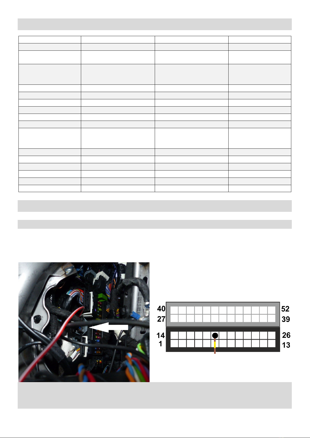
Ford S-Max
Warnblinkeransteuerung
Die Ansteuerung der Warnblinker befindet sich im Sicherungsraum links neben dem Lenkrad.
The tap point for the hazard flasher is located in the fuse compartment on the left side of the steering wheel.
Den 52 poligen BCM Stecker ausstecken und dann Pin 19 (braun-gelb) mit Pin 8 (braun-rot) des Kabelsatzes verbin-
den. Danach den BCM Stecker wieder einstecken.
Disconnect the 52 way BCM connector, then connect pin 19 (brown-yellow) with pin 8 (brown-red) of the cable harness. Recon-
nect the BCM connector afterwards.
Hersteller Manufacturer
CAN high
CAN low
CAN-Bus
Audi
wie VW see VW
BMW
grün-orange / schwarz
green-orange / black
grün / gelb green / yellow
Komfort comfort
Citroen
Nummerierung
am Kabel 9001
Numbering on the cable 9001
Nummerierung
am Kabel 9000
Numbering on the cable 9000
Motor engine
Fiat
weiß white
violett violet
Motor engine
Fiat
rosa-schwarz pink-black
rosa-weiß pink-white
Komfort comfort
Fiat
grau-schwarz grey-black
weiß-grün white-green
Komfort comfort
Ford
OBD Pin 6
OBD Pin 14
Motor engine
Ford
blau-grau blue-grey
lila-grün purple-green
Komfort comfort
Kia
orange orange
grün green
Peugeot
Nummerierung
am Kabel 9001
Numbering on the cable 9001
Nummerierung
am Kabel 9000
Numbering on the cable 9000
Motor engine
SEAT
wie VW see VW
Skoda
wie VW see VW
Volvo (XC 60)
violett-weiß violet-white
violett-grün violet-green
Komfort comfort
VW
orange-lila orange-purple
orange-braun orange-brown
Infotainment
VW
orange-grün orange-green
orange-braun orange-brown
Komfort comfort
VW
orange-schwarz orange-black
orange-braun orange-brown
Motor engine

3674700_R5 11.08.2020 Seite 4von 9
Volvo XC 60 II Gen. (2017-)
Der CAN Abgriff befindet sich am CEM hinter der Abdeckung links neben dem Lenkrad.
Verbinden Sie Pin 20 am FL Stecker des CEM (CAN High, violett-weiß) mit Pin 12 weiß-gelber Leitung des Kabelsatzes.
Verbinden Sie Pin 19 am FL Stecker des CEM (CAN Low, violett-grün) mit Pin 6 weiß-brauner Leitung des Kabelsatzes.
The CAN tap is located on the CEM behind the cover to the left of the steering wheel.
Connect pin 20 on the FL connector of the CEM (Can High, violet-white) with pin 12 white-yellow wire of the cable set.
Connect pin 19 on the FL plug of the CEM (Can Low, violet-green) with pin 6 of the white-brown cable harness.
Warnblinkertaster
Tastenleiste in der Mittelkonsole ausbauen. Pin 6 (braun-grau) am Stecker hinter der Tastenleiste mit Pin 8 (braun-
rot) des Kabelsatzes verbinden.
Hazard flasher switch
Remove the button strip in the centre console. Connect pin 6 (brown-grey) of the connector on the backside of the key cluster
with pin 8 (brown-red) of the cable harness.
Pin 6 (braun-grau) Pin 6 (brown-grey)
FL
CEM Stecker
CEM connector
3674700_R5 11.08.2020 Seite 5von 9
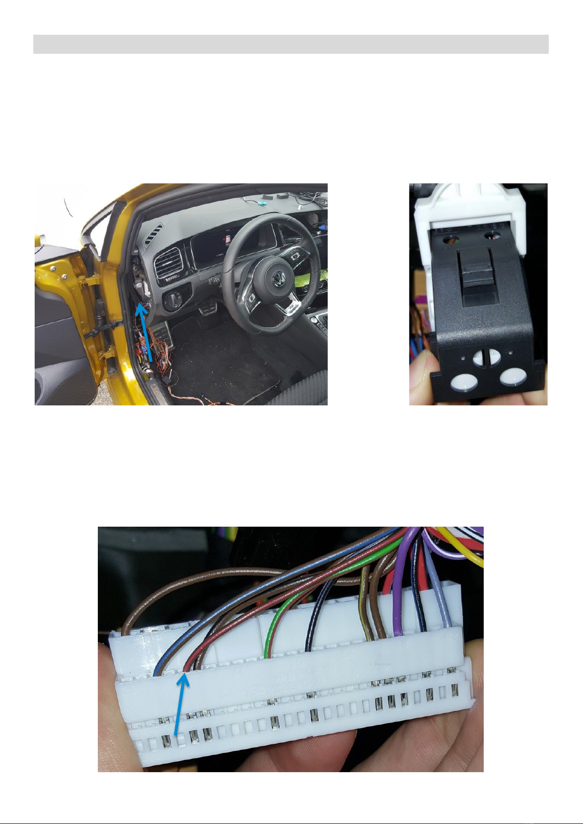
VW Golf VII / Passat B8
Warnblinkeransteuerung
Die Ansteuerung der Warnblinker befindet sich hinter der Plastikabdeckung links neben der Lichtregelung.
Der BCM befindet sich hinter der Fahrlichtsteuerung. Der darin steckende Stecker T73C befindet sich vom Fahrersitz
aus gesehen am nächsten und ist vom Stecker T73A zu unterscheiden durch die weißen Einsätze im T73C.
Hazard flasher control
The control of the hazard lights is located behind the plastic cover to the left of the light rack.
The BCM is located behind the headlight control. The T73C connector is the closest to the driver's seat, and can be distinguished
from the T73A connector by the white inserts in the T73C.
Golf VII: Den BCM Stecker T73C abstecken und Pin 42 (braun-rot) mit Pin 8 (braun-rot) des Kabelsatzes verbinden.
Danach den BCM Stecker wieder einstecken.
Golf VII: Disconnect the BCM connector T73C and connect pin 42 (brown-red) with pin 8 (brown-red) of the cable set.
After that, plug in the BCM connector again.
Passat B8: Den BCM Stecker T73C abstecken und Pin 42 (gelb-violett) mit Pin 8 (braun-rot) des Kabelsatzes verbin-
den. Danach den BCM Stecker wieder einstecken.
Passat B8: Disconnect the BCM connector T73C and connect pin 42 (yellow-violet) with pin 8 (brown-red) of the cable set.
Then plug in the BCM connector again.
3674700_R5 11.08.2020 Seite 6von 9
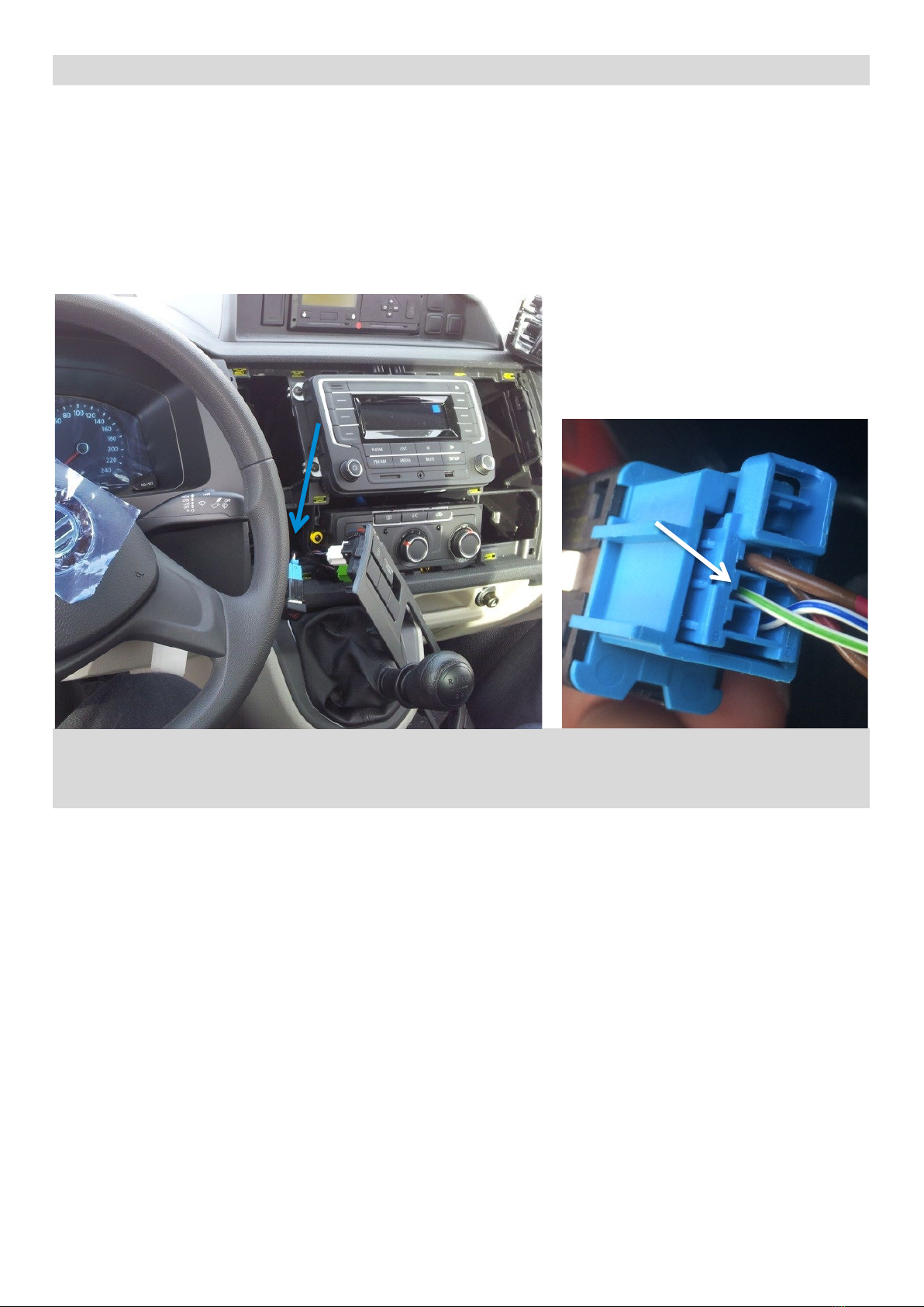
VW T6
Warnblinkertaster
Der blaue Stecker an der Rückseite des Warnblinkschalters befindet sich hinter der Plastikabdeckung im Passagier-
raum. Zuerst die Plastikabdeckung um das Radio herum entfernen, dann die Plastikabdeckung um die Klimakontrolle
entfernen. Der blaue Stecker an der Rückseite des Warnblinkschalters ist nun sichtbar.
Hazard flasher switch
The blue connector on the back of the hazard flasher switch is located behind the plastic cover in the cabin. Remove the upper
plastic cover around the radio first. Then remove the plastic cover around the climate control.
The blue connector on the back of the hazard flasher switch is now visible.
Die Leitung 8 (braun-rot) des Kabelsatzes wie oben gezeigt mit Pin 5 (grün-weiß) des blauen Steckers an der Rück-
seite des Warnblinkschalters.
Connect the wire 8 (brown-red) of the cable harness with the pin 5 (green-white) of the blue connector on the back of the haz-
ard flasher switch.
3674700_R5 11.08.2020 Seite 7von 9
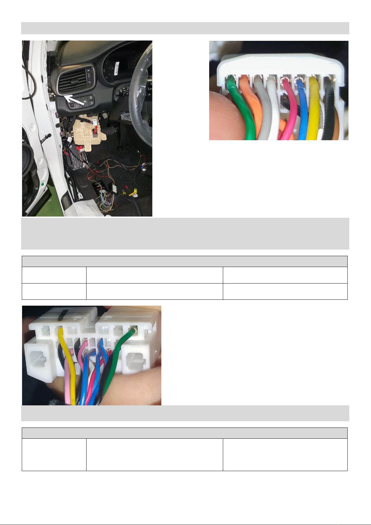
Kia Sorento III Gen. (UM, 2014-)
Der Abgriffpunkt befindet sich hinter dem Sicherungskasten im Fahrerfußraum.
Am weißen 16 poligen Stecker (H Main) den CAN-Bus abgreifen und mit dem Kabelsatz verbinden.
The tapping point is located behind the fuse box in the driver's footwell.
Tap the CAN bus at the white 16 pin connector (H Main) and connect it to the cable harness.
Abgriff CAN-Bus Tap CAN bus
CAN High
Pin 10 weißer Stecker (orange)
Pin 10 white connector (orange)
weiß gelbe Leitung am Kabelsatz
white yellow wire on cable harness
CAN Low
Pin 9 weißer Stecker (grün)
Pin 9 white connector (green)
weiß braune Leitung am Kabelsatz
white brown wire on cable harness
Am weißen 18 poligen Stecker (G Main) den CAN-Bus abgreifen und mit dem Kabelsatz verbinden.
Tap the CAN bus at the white 18-pin connector (G Main) and connect it to the cable harness.
Abgriff Warnblinker Tap hazard lights
Warnblinker
hazard lights
Pin 13 weißer Stecker (pink)
Pin 13 white connector (pink)
Ausgang für Warnblinker Pin 8 (rot-braun)
am Interface
Output for hazard lights Pin 8 (red-brown) on
the interface
A
9
10
13
3674700_R5 11.08.2020 Seite 8von 9
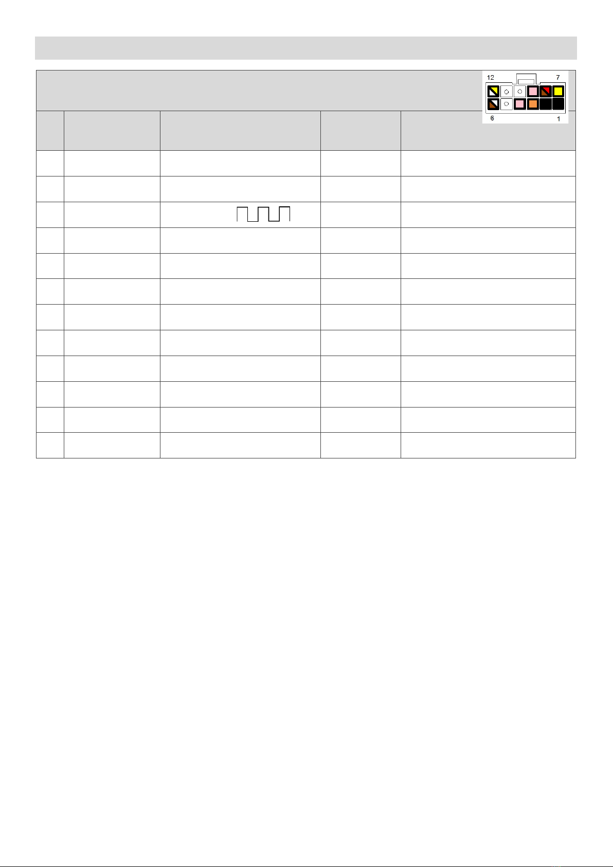
Anschlussbelegung – pin assignment
Anschlussbelegung 12-poliger Molex-Minifit Stecker
Pin assignment 12-pin Molex-Minifit connector
Pin Ein-/Ausgang
input/output
Bezeichnung
designation
Kabelfarbe
Cable colour
Bemerkung
remark
1
Eingang
input
Masse
ground
schwarz
black
Fahrzeugmasse ground
2
Eingang
input
Masse
ground
schwarz
black
Fahrzeugmasse ground
3
Ausgang
output
Takt Signal*
puls signal*
orange
orange
0V/12V max. 180 mA
4
Ausgang
output
Heckklappensignal*
trunk signal*
rosa
pink
12V max. 180 mA
5
nicht belegt
not assigned
--- --- ---
6
Eingang
input
CAN low
weiß-braun
white-brown
---
7
Eingang
input
Stromversorgung +12 V
Power supply +12 V
gelb
yellow
Dauerspannung
permanent voltage
8
Ausgang
output
Warnblinkeransteuerung
hazard light activation
braun-rot
brown-red
Masse geschaltet
switched to ground
9
Ausgang
output
Heckklappensignal*
trunk signal*
rosa
pink
12V max. 180 mA
10
nicht belegt
not assigned
--- --- ---
11
nicht belegt
not assigned
--- --- ---
12
Eingang
input
CAN high
weiß-gelb
white-yellow
---
* Optionale Ausgänge für zusätzliche Rücklichter oder zusätzliche Blinker z.B. innen am Heckdeckel
* Optional outputs for additional tail lights or additional indicators, e.g. inside tailgate

3674700_R5 11.08.2020 Seite 9von 9
Garantiebestimmungen – warranty conditions
Die speedsignal GmbH gewährleistet innerhalb der gesetzlichen Frist von 2 Jahren ab Datum des Erstkaufes, dass dieses
Produkt frei von Materialfehlern und Verarbeitungsfehlern ist, sofern dieses Produkt unseren Vorgaben entsprechend
verbaut wurde.
Sollten Reparaturen durch Verarbeitungsfehler oder Fehlfunktionen des Produktes innerhalb der Gewährleistungsfrist
nötig sein, wird die speedsignal GmbH das Produkt reparieren oder durch ein fehlerfreies Produkt ersetzen. Um die
Gewährleistung beanspruchen zu können, benötigen Sie einen Kaufbeleg.
Der Garantieanspruch erlischt durch:
unbefugte Änderungen am Gerät oder Zubehör
selbst ausgeführte Reparaturen am Gerät
unsachgemäße Nutzung bzw. Betrieb
Gewalteinwirkung auf das Gerät (Herabfallen, mutwillige Zerstörung, Unfall, etc.)
Beachten Sie beim Einbau alle sicherheitsrelevanten und gesetzmäßigen Bestimmungen.
Bitte beachten Sie generell beim Einbau von elektronischen Baugruppen in Fahrzeugen die Einbaurichtlinien und Ga-
rantiebestimmungen des Fahrzeugherstellers.
Sie müssen auf jeden Fall den Auftraggeber (Fahrzeughalter) auf den Einbau eines Interfaces aufmerksam machen und
über die Risiken aufklären.
Es empfiehlt sich, mit dem Fahrzeughersteller oder einer seiner Vertragswerkstätten Kontakt aufzunehmen, um Risi-
ken auszuschließen.
speedsignal GmbH guarantees within the legal deadline of 2 years from the original date of purchase that this product is free from
defects in material and workmanship as long as this product was installed similar to our installation guide.
If repairs of processing errors or malfunctions of this product are necessary within the warranty period, speedsignal will repair the
product or replace it with a flawless product. To be able to assert the benefit of these provisions, you need the proof of purchase.
Warranty claim and operating license lapses:
unauthorised changes on the device or accessory
self-initiated repairs at the device
improper use or operation
violent impacts to the device (fall down, wanton destruction, accident, etc.)
For installation, please notice all safety and legal regulations.
When installing electronic assemblies into vehicles please note the installation guidelines and warranty conditions of the vehicle
manufacturer.
In any case, you have to inform the principal (vehicle owner) about the installation of this interface and about all risks.
It is therefore recommended to get in contact with the vehicle manufacturer or with an authorized workshop to exclude any risks.
speedsignal GmbH Phone: +49 8061 49518 – 0 E-Mail: info@speedsignal.de
Carl-von-Ossietzky-Straße 3 Fax: +49 8061 49518 – 10 Homepage: www.speedsignal.de
D- 83043 Bad Aibling facebook: facebook.com/speedsignal
Table of contents
Other Speedsignal Automobile Accessories manuals

Speedsignal
Speedsignal RunLock User manual

Speedsignal
Speedsignal ADIF 332VW05 User manual

Speedsignal
Speedsignal RunLock B-339VW04 User manual

Speedsignal
Speedsignal 3444712 User manual

Speedsignal
Speedsignal B-339VW02 User manual

Speedsignal
Speedsignal B-3444756 User manual

Speedsignal
Speedsignal B-3406857 User manual

Speedsignal
Speedsignal Sound2Car User manual

Speedsignal
Speedsignal B-339MZ01 User manual

Speedsignal
Speedsignal 3474721 URI User manual


