Speedsignal RunLock B-339VW04 User manual

speedsignal GmbH Phone: +49 8061 49518 – 0 E-Mail: info@speedsignal.de
Carl-von-Ossietzky-Straße 3 Fax: +49 8061 49518 – 10 Homepage: www.speedsignal.de
D- 83043 Bad Aibling facebook: facebook.com/speedsignal
EINBAUANLEITUNG
Installation Guide
Motorweiterlaufschaltung
RunLock
VW Amarok Facelift (2016-), Caddy III (2K, 2015-)
Art.Nr. B-339VW04
10R-05 5004

B-339VW04_R2 15.05.2020 Seite 2von 12
Sicherheitshinweise – safety instructions
Der Einbau dieses Artikels darf nur von geschultem Fachpersonal vorgenommen werden und nur nach der in dieser
Anleitung beschriebenen Vorgehensweise.
Die speedsignal GmbH übernimmt keinerlei Haftung für Personen- oder Sachschäden, die mit dem Missbrauch unse-
rer Produkte im Zusammenhang stehen.
Vor der Montage bitte die Batterie abklemmen. Beim Einbau müssen alle zusätzlichen Versorgungsleitungen ent-
sprechend ihres Querschnittes und ihrer Kabellänge abgesichert werden. (DIN VDE 0298-4)
The installation of this product should only be carried out by trained specialist personnel and in accordance with this manual.
speedsignal GmbH cannot accept any liability for injury to persons or damage to property from errors or mistakes in this operat-
ing manual.
Please disconnect the battery before you start with the installation. During montage, all additional supply lines must be se-
cured pursuant to their cross section and cable length. (DIN VDE 0298-4)
Beschreibung – description
Die Motorweiterlaufschaltung ist eine elektrische Schaltung bei Kraftfahrzeugen, die es ermöglicht, das Fahrzeug bei
laufendem Motor zu verlassen. Eine Fremdnutzung wird durch Sicherheitsmaßnahmen ausgeschlossen. Zusätzlich
kann das Fahrzeug bei laufendem Motor von außen verriegelt werden.
Die Motorweiterlaufschaltung ist in erster Linie für Behördenfahrzeuge in Ausübung ihrer dienstlichen Pflicht vorge-
sehen. Beim Einbau in andere Fahrzeuge als Behördenfahrzeuge weisen wir darauf hin, dass ein unnötiges Laufenlas-
sen von Fahrzeugmotoren nach §30 I StVO verboten ist.
The RunLock is an electrical circuit in motor vehicles that makes it possible to leave the vehicle while the engine is running. Safe-
ty measures prevent unauthorized use. In addition, the vehicle can be locked from the outside while the engine is running.
Primarily it is intended for the use within authority vehicles in exercise of their duties.
For the installation into other vehicles (not authority) we point out that an unnecessary engine run is forbidden by law in many
countries such as in Germany according to StVO §30.
Lieferumfang – scope of delivery
Interface Runlock-Schaltung (MWS) Kabelsatz mit Zusatzkabel RunLock- Taster
RunLock cable set universal RunLock- button
3470079 C-3470078 6003131
Benötigtes Werkzeug - Required tools
Torx Schrauber Ausbauwerkzeug Bohrmaschine Lötkolben
Torx screwdriver removal tool drill soldering irons
Ø 12mm
Torx 20

B-339VW04_R2 15.05.2020 Seite 3von 12
Amarok Facelift (2016-)
Zusatzkabel einpinnen – pin additional cable
Grünes Kabel in Pin 4, weißes Kabel in Pin 9 und blaues Kabel in Pin 9 einpinnen.
Das Interface wird hinter der Fußraumabdeckung verbaut.
Pin green cable into pin 4, white cable into pin 9 and blue cable into pin 9
The interface is installed behind the footwell cover.
Abgriffspunkte – tap points
9
10
4
A
B
C
B
C
A

B-339VW04_R2 15.05.2020 Seite 4von 12
Einbau Amarok– installation Amarok
1
2
3
4
5
6
Seitliche Verkleidung abnehmen
Remove the side cover
Lenkradverkleidung entclipsen
Unclip the steering wheel cover
3 Schrauben oben / unten lösen
Loosen 3 screws top / bottom
Einstelltaster eindrücken und auf
Standlicht drehen.
Lichtschal-
terblock nun herausziehen.
Push in the setting button and turn
to parking light. Now pull out the
light switch block.
Schraube lösen und Verkleidung
abnehmen
Loosen
the screw and remove the
cover
Verkleidung unter dem Lenkrad
entclipsen
Unclip the cover under the steer-
ing wheel

B-339VW04_R2 15.05.2020 Seite 5von 12
Abgriffpunkt A – tap point A
Abgriff Türenschließer (Fußraum links)
Tap door closer (footwell left)
Kabelstrang
Cable harness
braun-rot
brown-red
Abgriff (A) hinter Fußraumabdeckung (links)
Tap (A) behind footwell cover (left)
Abgriffpunkte B & C – Tap point B & C
Abgriff RunLock (B), Zündschloss
Tap RunLock (B), ignition lock
6 poliger Stecker (PIN 2)
6 pole connector (PIN 2)
schwarz
black
Abgriff CAN high (C), Zentralelektrik Fahrerseite rechts
CAN high (C) tap, central electrics driver's side right
brauner Stecker
brown plug
orange-grün
orange-green
Abgriff CAN low (C), Zentralelektrik Fahrerseite rechts
CAN low (C) tap, central electrics driver's side right
brauner Stecker
brown plug
orange-braun
orange-brown
A
B
9
10
C
Abgriff (B) Zündschloss
Tap (B) ignition lock
Abgriff CAN Bus (C), Zentralelektrik Fah-
rerseite rechts
CAN
bus (C) tap, central electrics driver's
side right
4

B-339VW04_R2 15.05.2020 Seite 6von 12
Pin Belegung Kabelsatz Stecker - Pin Assignment Cable set Connector
Anschlussbelegung 12-poliger Minifit-Stecker
Pin assignment 12-pin Minifit connector
Ein-/Ausgang
input/output
Bezeichnung
designation
Kabelfarbe
cable colour
Bemerkung
remark
1
Eingang input
Masse ground
braun brown
---
2 Eingang input Masse ground braun brown
Masse RunLock-Taster
ground RunLock button
3
nicht belegt not assigned
---
---
---
4 Ausgang output Output LED grün green
Ausgang +12 V (Anzeige MWS)
Output +12 V (MWS display)
5
nicht belegt not assigned
---
---
---
6 Eingang input CAN Low
braun-weiß
brown-white
siehe Bild C, siehe S. 5
see picture C, see page 5
7 Eingang input Stromversorgung +12 V
Power supply +12 V rot red
Anschluss an Klemme 30
Passende Sicherung installieren!
Connection to clamp 30
Install a suitable fuse!
8
nicht belegt not assigned
---
---
---
9 Ausgang output Output MWS 1 weiß white
Ausgang +12 V (MWS aktiv), siehe Bild B
Output +12 V (MWS active), see picture B
10 Ausgang output Output MWS 2 blau blue
Ausgang +12 V (MWS aktiv), siehe Bild B
Output +12 V (MWS active), see picture B
11
nicht belegt not assigned
---
---
---
12 Eingang input CAN High
gelb-weiß
yellow-white
siehe Bild C, siehe S. 5
see picture C, see page 5
Anschlussbelegung 4-poliger Minifit-Stecker
pin assignment 4-pole minifit-plug
Ein-/Ausgang
input/output
Bezeichnung
designation
Kabelfarbe
cable colour
Bemerkung
remark
1
nicht belegt not assigned
---
---
---
2
nicht belegt not assigned
---
---
---
3
Eingang input Taster in button in lila purple
Taster RunLock
button RunLock
4
Ausgang output
Türenschließer
door closer
grün green
siehe Bild A, siehe S.4
see picture A, see page 4
Belegung Interface

B-339VW04_R2 15.05.2020 Seite 7von 12
Caddy III (2K, 2015-)
Zusatzkabel einpinnen – pin additional cable
Weißes Kabel in PIN 9 am Interface einpinnen.
Pin the white cable into PIN 9 on the interface.
Der Stecker für das MWS Signal und der CAN Abgriff befinden sich unter am Lenkradstock.
The connector for the RunLock signal and the CAN tap are located under the steering wheel column.
Obere und untere Lenkradabdeckung entfernen. Dazu drei Torx 20 Schrauben lösen.
Remove the upper and lower steering wheel covers. To do this, loosen three Torx 20 screws.
Torx 20
9
A

B-339VW04_R2 15.05.2020 Seite 8von 12
Stecker mit dem CAN Abgriff und dem RunLock Abgriff befinden sich unter dem Lenkrad.
Connector with the CAN tap and the RunLock tap are located under the steering wheel
CAN und RunLock signal abgreifen.
Wie in folgender Tabelle beschrieben mit dem Hauptkabelsatz verbinden:
Tap CAN and RunLock signal.
Connect to the main cable harness as described in the following table:
Abgriff am Stecker - Tap on connector
Signal
Stecker (16pol. Stecker)
Connector (16-pin plug)
Hauptkabelsatz C-3470078
Main cable harness C-3470078
RunLock
Pin 14
schwarz black
Pin 9
weiß white
CAN high
Pin 4
orange-grün orange-green
Pin12
gelb-weiß yellow-white
CAN low
Pin3
orange-braun orange brown
Pin 6
braun-weiß brown-white

B-339VW04_R2 15.05.2020 Seite 9von 12
BCM Einstellung setzen (nur VW CADDY ) - Configure BCM setting (VW CADDY only)
Um das Fahrzeug bei aktiver MWS verschließen zu können, muss die BCM Einstellung korrekt sein.
Die Einstellung sind im Control Module „09-Cent. Elect.“ zu finden. Dort muss im Byte 4 das Bit 2 auf 1 stehen.
In order to lock the vehicle with RunLock active, the BCM setting must be correct.
The setting is stored in the Control Module "09-Cent.Elect." There, bit 2 in byte 4 must be set to 1.

B-339VW04_R2 15.05.2020 Seite 10 von 12
Pin Belegung Kabelsatz Stecker - Pin Assignment Cable set Connector
Anschlussbelegung 12-poliger Minifit-Stecker
Pin assignment 12-pin Minifit connector
Ein-/Ausgang
input/output
Bezeichnung
designation
Kabelfarbe
cable colour
Bemerkung
remark
1
Eingang input
Masse ground
braun brown
---
2 Eingang input Masse ground braun brown
Masse RunLock-Taster
ground RunLock button
3
nicht belegt not assigned
---
---
---
4 Ausgang output Output LED grün green
Ausgang +12 V (Anzeige MWS)
Output +12 V (MWS display)
5
nicht belegt not assigned
---
---
---
6 Eingang input CAN Low
braun-weiß
brown-white
siehe S.8
see page 8
7 Eingang input Stromversorgung +12 V
Power supply +12 V rot red
Anschluss an Klemme 30
Passende Sicherung installieren!
Connection to clamp 30
Install a suitable fuse!
8
nicht belegt not assigned
---
---
---
9 Ausgang output Output MWS 1 weiß white
Ausgang +12 V (MWS aktiv), siehe Seite 8
Output +12 V (MWS active), see page 8
10
nicht belegt not assigned
---
---
---
11
nicht belegt not assigned
---
---
---
12 Eingang input CAN High gelb-weiß
siehe S.8
see page 8
Anschlussbelegung 4-poliger Minifit-Stecker
pin assignment 4-pole minifit-plug
Ein-/Ausgang
input/output
Bezeichnung
designation
Kabelfarbe
cable colour
Bemerkung
remark
1
nicht belegt not assigned
---
---
---
2
nicht belegt not assigned
---
---
---
3
Eingang input Taster in button in lila purple
Taster RunLock
button RunLock
4
nicht belegt not assigned
---
---
---
Belegung Interface

B-339VW04_R2 15.05.2020 Seite 11 von 12
Funktionsprüfung und Inbetriebnahme - functional test and commissioning
Für eine erfolgreiche Aktivierung der Motorweiterlaufschaltung sind folgende Schritte notwendig:
1. Motor starten
2. Handbremse anziehen
3. Automatik auf Stellung „P“ stellen
4. Füße von den Pedalen nehmen
5. RunLock-Taster blinkt -> drücken -> Taste leuchtet durchgängig
6. aus dem Fahrzeug steigen
7. Türe verschließen
Zur Deaktivierung der Motorweiterlaufschaltung beachten Sie bitte folgende Vorgehensweise:
1. Fahrzeug entsperren
2. Aus Sicherheitsgründen muss bei Keyless Fahrzeugen der Motor gestoppt werden, damit das Fahrzeug den
Schlüssel erneut überprüft
3. RunLock-Taster drücken
Bei Betätigung des Brems- oder Kupplungspedals VOR dem Ausschalten der Motorweiterlaufschaltung schaltet
sich der Motor automatisch aus.
Leucht- und Blinkverhalten des RunLock-Tasters:
Taster blinkt: Alle Voraussetzungen für die Aktivierung der Motorweiterlaufschaltung sind gegeben.
Taster leuchtet durchgehend: Die Motorweiterlaufschaltung ist erfolgreich aktiviert.
Taster leuchtet nicht mehr: Die Motorweiterlaufschaltung ist erfolgreich deaktiviert.
The following steps are necessary for successful activation of the RunLock:
1. start motor
2. apply handbrake
3. automatic mode set to position "P
4. take your feet off the pedals
5. RunLock button flashes -> press -> button lights up continuously
6. get out of the vehicle
7. close the door
For deactivating RunLock, please observe following procedure:
1. unlock the vehicle
2. for safety reasons, in keyless vehicles the engine must be stopped for the vehicle to re-check the key
3. press RunLock button
If the brake or clutch pedal is actuated BEFORE the engine is switched off, the engine switches off automatically.
Illumination and flashing behaviour of RunLock button:
button flashes: All conditions for activating the RunLock are fulfilled.
button illuminates constantly: RunLock is activated successfully
button does not illuminate: RunLock is deactivated successfully

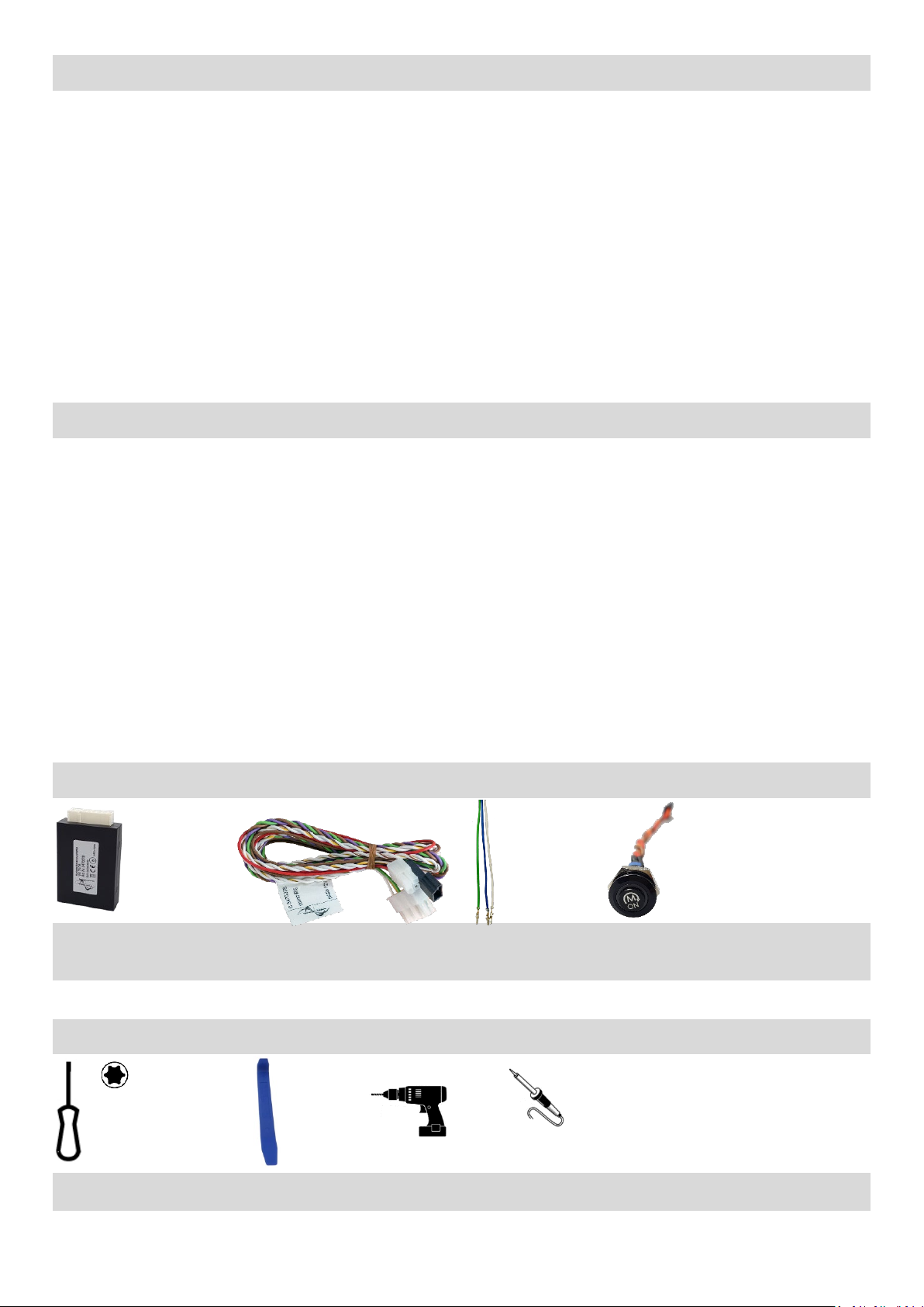
B-339VW04_R2 15.05.2020 Seite 12 von 12
Garantiebestimmungen - Warranty Conditions
Die speedsignal GmbH gewährleistet innerhalb der gesetzlichen Frist von 2 Jahren ab Datum des Erstkaufes, dass
dieses Produkt frei von Materialfehlern und Verarbeitungsfehlern ist, sofern dieses Produkt unseren Vorgaben ent-
sprechend verbaut wurde.
Sollten Reparaturen durch Verarbeitungsfehler oder Fehlfunktionen des Produktes innerhalb der Gewährleistungs-
frist nötig sein, wird die speedsignal GmbH das Produkt reparieren oder durch ein fehlerfreies Produkt ersetzen. Um
die Gewährleistung beanspruchen zu können, benötigen Sie einen Kaufbeleg.
Der Garantieanspruch erlischt durch:
unbefugte Änderungen am Gerät oder Zubehör
selbst ausgeführte Reparaturen am Gerät
unsachgemäße Nutzung bzw. Betrieb
Gewalteinwirkung auf das Gerät (Herabfallen, mutwillige Zerstörung, Unfall, etc.)
Beachten Sie beim Einbau alle sicherheitsrelevanten und gesetzmäßigen Bestimmungen.
Bitte beachten Sie generell beim Einbau von elektronischen Baugruppen in Fahrzeugen die Einbaurichtlinien und
Garantiebestimmungen des Fahrzeugherstellers.
Sie müssen auf jeden Fall den Auftraggeber (Fahrzeughalter) auf den Einbau eines Interfaces aufmerksam machen
und über die Risiken aufklären.
Es empfiehlt sich, mit dem Fahrzeughersteller oder einer seiner Vertragswerkstätten Kontakt aufzunehmen, um Risi-
ken auszuschließen.
speedsignal GmbH guarantees within the legal deadline of 2 years from the original date of purchase that this product is free
from defects in material and workmanship as long as this product was installed similar to our installation guide.
If repairs of processing errors or malfunctions of this product are necessary within the warranty period, speedsignal will repair
the product or replace it with a flawless product. To be able to assert the benefit of these provisions, you need the proof of pur-
chase.
Warranty claim and operating license lapses:
unauthorised changes on the device or accessory
self-initiated repairs at the device
improper use or operation
violent impacts to the device (fall down, wanton destruction, accident, etc.)
For installation, please notice all safety and legal regulations.
When installing electronic assemblies into vehicles please note the installation guidelines and warranty conditions of the vehicle
manufacturer.
In any case, you have to inform the principal (vehicle owner) about the installation of this interface and about all risks.
It is therefore recommended to get in contact with the vehicle manufacturer or with an authorized workshop to exclude any
risks.
speedsignal GmbH Phone: +49 8061 49518 – 0 E-Mail: info@speedsignal.de
Carl-von-Ossietzky-Straße 3 Fax: +49 8061 49518 – 10 Homepage: www.speedsignal.de
D- 83043 Bad Aibling facebook: facebook.com/speedsignal
Table of contents
Other Speedsignal Automobile Accessories manuals

Speedsignal
Speedsignal B-3406857 User manual

Speedsignal
Speedsignal ADIF 332VW05 User manual

Speedsignal
Speedsignal RunLock User manual

Speedsignal
Speedsignal 3474721 URI User manual

Speedsignal
Speedsignal B-3674700 User manual

Speedsignal
Speedsignal B-339MZ01 User manual

Speedsignal
Speedsignal B-3444756 User manual

Speedsignal
Speedsignal B-339VW02 User manual

Speedsignal
Speedsignal 3444712 User manual

Speedsignal
Speedsignal B-339VW01 User manual