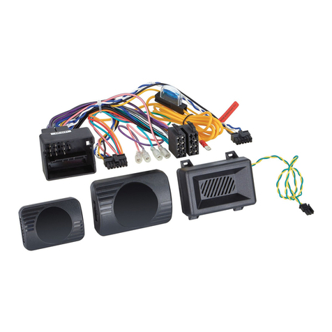
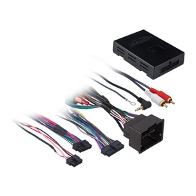
Speedsignal 3474721 URI User manual

Folgende Funktionen werden vom
Interface unterstützt:
Features supported by Interface :
Kl 15 (ACC) / ignition
Rückw rtsgang / reverse
Beleuchtung / illumination
Geschwindigkeit / speed
Handbremse / parking brake
Anzeige im Display bei: W208, W209,
W203 / display output for: W208, W209, W203
speedsignal GmbH
Carl-von-Ossietzky-Straße 3
D-83043 Bad Aibling
Tel: +498061 / 495180
Fax: +498061 / 4951810
info@speedsignal.de
www.speedsignal.de
Universal Remote Interface
3474721 URI
3470010 URI
Mercedes/VW Fahrzeuge / vehicles
CAN-Bus Interface mit Unterstützung der Lenkradtasten
C N-Bus interface with steering wheel remote control
Technische Änderungen und Copyright vorbehalten Copyright and technichal changes under reserve.
enkradfunktionen
steering wheel remote control
Fahrzeuge vehicles
11.03.15 Datenblatt /specification 3474721 Rev. 5 Seite /page 1/4
1
2
6
7
8
3
4
5
Ausbau Serien-Radio removal OE radio
Zündschlüssel abziehen und Radio mit passendem Ausbauwer zeug herausziehen. Falls nicht vorhanden bitte an
Mercedes Vertragswer stätte wenden.
draw-off the car key and remove the radio (to remove the radio, you will need the corresponding removing tool or
help from your Mercedes dealer.)
-A-Klasse (W169, 2005-2012)
-B-Klasse (W245, 2005-2012)
-C-Klasse (W203, 2001-2007)
-C K (W208, mit CAN)
-C K (W209, 2002-2005 & 2005-2010)
-E-Klasse (W211, 2002-2006)
-E-Cabrio (A207, 2010-)
-R-Klasse (W251, 2005-)
-S K (R171, 2004-2011)
-Sportcoupe (C 203, 2000-2011)
-M-Klasse (W164, 2005-2008)
-Viano/Vito (W639, 2003-2010)
-Sprinter II (NCV3 W906, 2006-)
-VW Crafter (2006-)
Lenkradtaste /
steering-wheel
key
Kommando / command
Lautstär e + / volume +
Untermenü wählen / select submenu
Lautstär e - / volume -
Untermenü wählen / select submenu
Nur im Audiomenü: Titel + /
UDIO menu only: track +
Nur im Audiomenü: Titel - /
UDIO menu only: track -
Menü + / menu up
Menü - / menu down
Anruf annehmen / accept call
Anruf ablehnen / reject call
1
2
3
4
5
6
7
8

Technische Änderungen und Copyright vorbehalten Copyright and technichal changes under reserve.
*1) Für alle Blaupunkt Radioger te aus Gruppe 2 (siehe
Übersichtstabelle auf letzter Seite) / for all Blaupunkt radio
devices of group 2 (see Overview Table on last page)
*2) Explizit für das Radioger t Zenec ZE-NC514 / exclusively for the
radio device Zenec ZE-NC514
*3) Für alle Axion Radioger te aus Gruppe 1 sowie Grundig
Radioger te / for all xion radio devices of group 1 as well as
Grundig radio devices
DIP Schalter
DIP switches 1234
– Audiovox 0 0 0 0
– Blaupunkt 1 0 0 0
-Alpine 0100
-Kenwood 1100
-JVC 0010
-Blaupunkt II *1) 1010
-Clarion 0110
-Macrom 1110
-Zenec 0001
-Snooper/Eclipse 1001
-Zenec II *2) 0101
-Axion II 1101
-Grundig/Axion *3) 0011
-Sony 1011
-Pioneer 0111
-Becker 1111
Radio radio
0
DIP-Schalter 1-4 müssen entsprechend der Tabelle gesetzt
werden / DIP Switches 1-4 have to be set corresponding to the table
1
# DIP –Schalter
unterstütztes Fahrzeug
DIP switches supported vehicle
DIP 5 – 8
I ≙ ON
0 ≙ OFF
5 6 7 8
1Alle, außer Frz. aus Schalterstellung 2, 3 und 4 /
all, except the cars from DIP switch pos. 2, 3 and 4
Fun tion Ausgangspin 8: Handbremse /
Function Output 8: Parking Brake
1 0 0 0
2C-Klasse (W203), CLK (W209, 2002-2005), Sportcoupe
(CL203) (Display)
Fun tion Ausgangspin 8: Handbremse /
Function Output 8: Parking Brake
0 1 0 0
3CLK (W208), (W210) (Display)
Fun tion Ausgangspin 8: Handbremse /
Function Output 8: Parking Brake
1 1 0 0
4A-Klasse (W169), B-Klasse (W245), Viano Vito (W639)
Fun tion Ausgangspin 8: Handbremse /
Function Output 8: Parking Brake
0 0 1 0
Programmierung der DIP – Schalter (innenliegend)
coding DIP switches (inside)
Fahrzeug vehicle
Farbe / colour Beschreibung / description
Grün / green CAN a tiv / C N active
Gelb / yellow Ausgang „Kl15“ a tiv / output „ignition“ enabled
11.03.15 Datenblatt /specification 3474721 Rev. 5 Seite /page 2/4

Technische Änderungen und Copyright vorbehalten Copyright and technichal changes under reserve.
Kabelsatz Fahrzeug cable harness vehicle
Kabelsatz / cable harness C-3474721 AUDIO 5 Kabelsatz / cable harness C-3474722 AUDIO 10
Kabelsatz / cable harness C-3474723 AUDIO 20 (2006-) (NTG2)(APS50)
Handbremse / Parking Brake Handbremse / Parking Brake
Handbremse / Parking Brake
Kabelsatz / cable harness C-3474724 AUDIO 20 (-2006) (NTG1)
Handbremse / Parking Brake
Abgriff CAN-Bus bei Radiovorbereitung tap CAN bus by radio preparation
Falls das Fahrzeug keinen CAN-Bus am Radio anliegen hat / i CAN-Bus can not be ound on Radio connector:
CAN-Bus an beliebiger Stelle im Innenraum abgreifen. Der CAN-Bus ist an den meisten Einbauorten als verdrilltes
Adernpaar zu finden.
C N-bus can be tapped in vehicle interior at optional places as a twisted pair of wires.
CAN HIGH braun/rot / brown/red
CAN LOW braun / brown
Beispiele / Examples :
- Am Stec er des Klimabedienelements / behind the climate control board
- Unter dem rechten Vordersitz / below the co-driver seat.
11.03.15 Datenblatt /specification 3474721 Rev. 5 Seite /page 3/4

Technische Änderungen und Copyright vorbehalten Copyright and technichal changes under reserve.
Bei Fahrzeugen mit Radiovorbereitung muss ein Audio 5 mit Telefon einprogrammiert werden
vehicles with a radio prepatation have to be programmed with an audio 5 with telephone
- Star Diagnose starten / Start Star Diagnose
- Menüpunkt “Steuergeräte Anpassung” ausw hlen / choose menu item “configure control unit”
- Menüpunkt “Codierung lesen und ggf. Ändern” / menu item “read and change coding”
- Menüpunkt “Allgemeiner Parametersatz” / menu item “general parameters”
- Auswahlmenü “Audioanlage” auf aktiv setzen / options “audio unit” set active
Fahrzeuge ohne Audiomenü mit Radiovorbereitung Vehicles without audio menue with
radio preparation
Konfiguration muss nur in lteren Fahrzeugen durchgeführt werden, bei denen die Funktion Titel +
und Titel - nicht stetig im Audio Menü bleibt. Diese Funktion verschiebt sich dann in andere
Menüpunkte.
Vorbereitung:
-Interface und Radio einbauen
-Zündung an
-evtl. anstehende Störungen (Lampe defekt, o. .) quittieren
-ins Audio Menü wechseln
Durchführung Konfiguration
-Lenkradtaste für „Anruf ablehnen“ drücken und halten
-gleichzeitig 4x hintereinander „skip down“ drücken („Anruf ablehnen“ ist immer noch gedrückt)
-daraufhin schaltet sich der Rückw rtsgang und die Beleuchtung ein
-„Telefon auflegen“ Taste loslassen
-Menü vorw rts so oft drücken, bis wieder im Audio Menü angelangt
-„Telefon auflegen“ Taste erneut drücken
-Zündung aus
Zündung an, die Konfiguration ist beendet.
Anstehende Störungen nur mit und quittieren!
Konfiguration con iguration o URI inter ace in Mercedes
Nur Schalterstellung 1 / only Dip switch 1
Configuration has only to be done in older cars where the function Track + and Track – switches
between the menus
Preparation:
-installation of RI interface and radio.
How to configure your RI interface
-turn car key to “ignition” and switch on the navigation system
-acknowledge all error messages appearing on on-board-computer
-move to audio menu (press the „menu up“-button until audio window is shown in the display).
-press the button „reject call“ and keep it pressed until the navi display switches to night design.
The M- RI interface is in the configuration mode now.
-press the „menu up“-button once and again, until audio display is shown in the display again.
-press the button „reject call” and keep it pressed until the navi display switches back to day
design.
The configuration is completed now.
It can be done and repeated whenever necessary.
Error messages only quit with and !
11.03.15 Datenblatt /specification 3474721 Rev. 5 Seite /page 4/4

*) Der maximal zulässige Strom pro Ausgang beträgt 180mA. Gleichzeitig ist auf einen Gesamtausgangsstrom aller
Ausgänge zusammen von maximal 200mA zu achten, da sonst das Interface zerstört werden kann. Bei höherem Strombedarf
Zündung, Rückfahrsignal) ein Relais mit einem Spulenwiderstand von min. 75'Ω oder min. 150'Ω bei zwei Relais verwenden.
Wir empfehlen unser ER70.
*) The maximum rate of current per output is 180mA. Also, the total current of all outputs together must not exceed 200mA .Otherwise,
the interface could be damaged. In case a higher current is needed (ACC, reverse signal ) a relay whith a coil resistance of min. 5"Ω or
min. 150"Ω by use of two relays. We advise to use our ER 0.
Disclaimer:
Bitte beachten Sie, generell beim Einbau von elektronischen Baugruppen in Fahrzeugen, die Einbaurichtlinien und Garantie-
bestimmungen des Fahrzeugherstellers. Sie müssen auf jeden Fall den Auftraggeber Fahrzeughalter) auf den Einbau eines
Interfaces aufmerksam machen, und über die Risiken aufklären. Es empfiehlt sich mit dem Fahrzeughersteller oder einer seiner
Vertragswerkstätten Kontakt aufzunehmen, um Risiken auszuschließen.
Please strictly refer to the automobile manufacturers installation guide lines and terms of warranty, when installing electronic units in
automobiles. Inform the customer (car owner) about the installation and the related risks. To disclaim, it may be useful to contact the automobiles
manufacturer or an authorized workshop.
Technische Änderungen und Copyright vorbehalten Copyright and technical changes under reserve.
Pinbelegung / pin configuration 12 pol Molex Mini it
PIN
pin
Signal
signal
Typ
type
Beschreibung
description
Bemerkung
note
1 Kl. 31 In Masse / ground
2 Kl. 31 In Masse / ground
3 Kl. 58 Out*) Beleuchtung / illumination Ausgang 0'V: Licht aus / Ausgang 12'V: Licht an
output 0 V: illumination off / output 12 V: illumination on
4 R Out *) Rückwärtsgang / reverse Ausgang / output 0"V: off≙ /
Ausgang / output 12"V: on ≙
5 BTP 3.15 Out Becker® Fernbedienung
Becker® remote control
Zur Fernsteuerung einer Becker® Navigation. Kammer C3,
Pin15)
remote control of Becker® navigation (chamber C3, Pin15)
6 CAN L In CAN LOW
7 Kl. 30 In +12V Dauerplus /
+ 12V battery plus
Das Interface ist für 12V'DC ausgelegt.
interface is designed for 12V d.c. voltage
8 Mute / HB Out Stummschaltung / mute
Handbremse / parking brake
Masse Ausgang je nach Schalterstellung
output ground is according to switch setting
9 Kl. 15 / ACC Out *) ACC / ignition Ausgang 0V: Zündung aus / Ausgang 12 V: Zündung an
output 0 V: ignition off / output 12 V: ilgnition on
10 Speed Out *) Rechtecksignal, proportional zur
Geschwindigkeit
rectangular signal, proportional to speed
Rechtecksignal 0 .. 12'Volt, ca. 1'Hz per km/h
rectangular signal 0 .. 12"Volt, approx. 1"Hz per km/h
11 BTP 3.16 Out Becker® Fernbedienung
Becker® remote control
Zur Fernsteuerung einer Becker® Navigation. Kammer C3,
Pin16)
remote control of Becker® navigation (chamber C3, Pin16)
12 CAN H In CAN HIGH
Pinbelegung / pin configuration 4 pol Molex Mini it
PIN
pin
Signal
signal
Typ
Type
Beschreibung
description
Bemerkung
note
1Kl. 31 Out Masse / ground
2RC5 out Out Fernsteuerungsausgang digital
remote control system digital
3RC3 in In Lenkradtasteneingang analog
steering-wheel key input analog
4RC3 out Out Fernsteuerungsausgang analog
remote control systems analog
4pol MiniFit Stecker
4-pin MiniFit connector
12pol MiniFit Stecker
12-pin MiniFit connector
Ein- und Ausgänge inputs and outputs
01.10.12 Revision 0

ÜbersichtdervomRadiounterstütztenFunktionen
CD
Radio
CD
Radio
CD
Radio
CD
Radio
CD
Radio
CD
Radio
CD
Radio
Lautstärke+/Vol+
Lautstärke‐/Vol‐
Titel+/Track+
Titel‐/Track‐
Senderspeicher+/Preset+
Senderspeicher‐/Preset‐
Sendersuche+/Seek+
Sendersuche‐/Seek‐
Band
Senderspeicher+/Preset+
Senderspeicher‐/Preset‐
Ordner+/Folder+
Ordner‐/Folder‐
Sendersuche+/Seek+
Sendersuche‐/Seek‐
Ordner+/Folder+
Tel.annehmen/acceptcall(*)
Tel.ablehnen/Rejectcall(*)
Tel.(*)
Quellenwahl/Source
Stummschaltung/Mute
Band
Ein‐/Ausschalten/Power
Sprachwahl/pushtotalk(PTT)
Senderspeicher+/Preset+
Sendersuche+/Seek+
Ordner+/Folder+
Lenkradtaste im
Fahrzeug /
Steering‐wheel
key in vehicle
Radio
CD
Radio
CD
Radio
Radiofunktion / radio device
event
CD
Radio
CD
Axion
Alpine
Pioneer
Kenwood
Clarion
Blaupunkt
Sony
Phonocar
Eclipse
Grundig
Gruppe 1 /
Group1
Gruppe 2 /
Group2
Gruppe 3/
Group3
Gruppe 1 /
Group1
Gruppe 2 /
Group2
CD
Radio
CD
Radio
CD
Radio
CD
Radio
Gruppe 2 /
Group2
JVC
Macrom
Zenec
Audiovox
Gruppe 1 /
Group1
CD
Radio
CD
Radio
CD
Radio
AxionGruppe1/Group1:CR1122D
AxionGruppe2/Group2:DVD1030NAV
JVCGruppe1/Group1:KD‐SH1000undältereGeräte
/andolderdevices
JVCGruppe2/Group2:KD‐R821BT
BAND
SRC
BAND
✔:vorhanden/available
(*):NurfallsvomRadiogerätunterstützt/Onlyifsupportedbytheradiodevice
BlaupunktGruppe1/Group1:OrlandoMP46undältereGeräte/and
olderdevices
BlaupunktGruppe2/Group2:Madrid210,Toronto410BT
BlaupunktGruppe3/Group3:SanFrancisco300
AusgabestandR1vom01.02.2013
This manual suits for next models
1
Table of contents
Other Speedsignal Automobile Accessories manuals
Speedsignal
Speedsignal B-3406857 User manual
Speedsignal
Speedsignal Sound2Car User manual
Speedsignal
Speedsignal B-3444756 User manual
Speedsignal
Speedsignal RunLock B-339VW04 User manual
Speedsignal
Speedsignal B-3674700 User manual

Speedsignal
Speedsignal B-339VW01 User manual
Speedsignal
Speedsignal B-339MZ01 User manual
Speedsignal
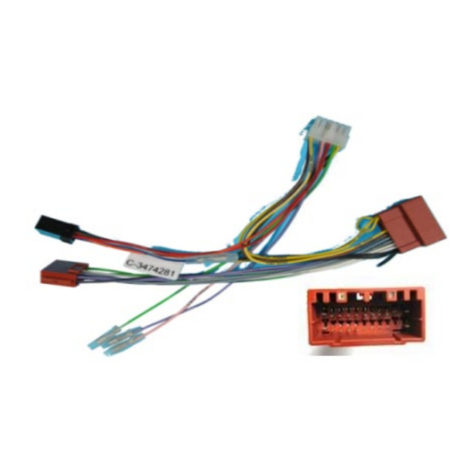
Speedsignal B-3474782 User manual
Speedsignal
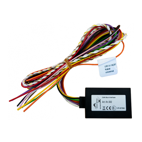
Speedsignal ADIF 332VW05 User manual
Speedsignal
Speedsignal RunLock User manual
