Spin OK CLIMA User manual

1
Instruction
manual
Spin srl
Via Casalecchio 35 - Rimini Italy - tel.0039.0541 730777 -731315
GB

2

3
Cap. 1 – Gene al info mation – secu ity egulations -
Page 4
Cap. 2 - Technical specifications Page 5
Cap. 3 - Installation of secu ity pa amete Page 6
Cap. 4 – Desc iption of the station Page 7
Cap. 5 – P epa ation of the station Page 9
Cap. 6 – Using of the Station Page 10
- Gas echa ge
- P essu e test AC
- Manual
- Half-automatic
- Automatic
- Data base
- Utility
Cap. 7 – Maintenance Page 16
Cap. 8 – Help on finding default functions Page 18
Cap. 9 – Plan fo blockage of functions Page 19
Cap. 10 Gua antee Page 20
List Data bank Page 21
DECLARATION OF CONFORMITY CE Page 22
CONTENTS

4
1.0 SCOPE OF THE MANUAL
This manual is supposed fo the using and maintenance of the ecycling, ecove y, vacuum and echa ge
station OK CLIMA. It is absolutely necessa y to ead this manual attentively befo e the using
the device. This
device is equipped with means of secu ity, which a e helpful to p otect the use against ha ms o inju ies.
The p oduce denies eve y esponsibility fo damages, which can be caused th ough false t eatment of the
devices by the use es
pecially if the using of the secu ity devices has not been adhe ed to. The inst uction
manual is a fi m pa t of the device and needs to accompany it eve y time, even in case of sale.
This symbol is being used if the inst uctions of the
manual a e not being espected o a false inte p etation
of the inst uctions is p esent this can cause inju ies to
people.
The device is being identified via a sign, which shows the desc iption of the model, the const uction yea and
the se ial numbe . The sign is attached to the side of the device. (fig,1).
ATTENTION
The device is supposed o be only for specialis s, which are familiar wi h Freon sys ems and he
damages/injuries hey can cause.
The OK CLIMA-device is capable to pe fo m the ph
ases of ecove y, ecycling, vacuum and
Recha ge in A/C systems of vehicles and indust ial vehicle, which contain the cooling liquid
R 134. Each esponsibility of the p oduce ceases at the fo bidden use of a diffe ent cooling
Liquid/f eon.
1.1 SECURITY FEATURES
Fo the wo k in the p esence of f eon it is absolutely necessa y to wea p otection gloves and
p otection glasses.
Use the device at b
est in a oom which is well ai ed in o de to avoid possible inhalation of the
f eon.
If the F eon comes into contact with the skin accidentally pe fo m as follows:
1) Wash the zones in question with wate ;
2) Remove ca efully the contaminated p otection clothes.
Ca eful: the p otection suits can sting/glue to the skin and can cause fi e inju ies in case of
f ost;
3) Consult a docto .
In case of accidental contact with the eyes perform as follows:
1) Rinse the eyes well with wate and contact a docto immediately.
If the freon is accidentally swallowed perform as follows:
1) Wash well you mouth and d ink lots of wate .
2) Contact medical assistance.
CAP. 1 GENERAL INF RMATI N
ATTENTION
Fig.
1

5
Enclosed Accessories:
1 Low p essu e hose l = 3mt
1 High p essu e hose 1 = 3 mt
1 Quick coupling low p essu e
1 Quick coupling high p essu e
1 Plastic bottle with 250 g fo f esh oil filling
1 Plastic bottles with 250 g fo old oil discha ge
1 cable powe supply
Accessories on reques :
Detecto ’s lamp A t. 19CR expo t SI
Elect onic leak sea ch device TIF RX-1
O-Ring-Set 150 in Viton A t.47CR
O-Ring-Set 360 in Viton, A t. 47.3CR
Digital-The momete DT10K
Oil containe fo R134a, A t.21CR
Oil containe fo vacuum pump 1/2lt A t. AV68I
Data base and elect ical switch plan + CD-Rom fo A/C plants A t. 037.14DT
Ret ofit kit fo A/C plants A t. Ret ofit 715
Leakage sealing set fo A/C plants A t. Supe Seal
TECHNICAL CHARACTERISTICS
Comp esso :
Capacity:
Recove y capacity (liquid phase)
He metic with the ecove ed automatic oil
1/3 PS
400g /min
Vacuum pump:
Capacity:
Vacuum g ad:
One-step
4m
3
/h
7x10
2
Vacuum test: Automatically with ala m sound and message on display
Deposit bottle:
Capacity of f eon:
With heating – two containe s and secu ity valve
18Kg
Exactness of scale:
+
/
-
10g
Cu ent Supply: 220v
Loudness: unde 80dB (measu ed with sound level mete class 2 acco ding
to no m IEC 651.804)
Tube length: 3 mt
Measu ements of the devices:
Weight: Kg
CAP. 2 TECHNICAL SPECIFICATI NS
Fig.2
Accesso ies in addition

6
3.0 RECOMMENDATIONS FOR THE CORRECT USE OF THE DEVICE
Please check befo e the switching-on of the device whethe oil is p esent in the vacuum pump:
If oil is missing fill it up to the level which has to be visible with the adequate cap.
Use exclusively mine al oil fo vacuum pumps Type AV68 (a t. AV68I).
3.1 INSTALLATION
The device has to be t anspo ted and set-up in ve tical position. Tilting the device can cause exit of oil f om
the vacuum pump and the comp esso . The device may only be used on even floo s. It is not advisable to use it
on unknown a ea outside the wo kshop.
3.2 PREPARATION OF THE STATION
Assu e you self befo e the sta ting of the station, that the net tension is as shown on the shield, which is
displayed close to the socket of the switch.
IMPORTANT
It is advised to adhe e absolutely st ict to the secu ity featu es given above. They a e given
fo the p otection of the pe sonnel, which is using the systems and the cooling liquid/f eon
unde p essu e
3.3 PERFORMABLE WORKS
The OK CLIMA is capable to pe fo m the following phases: ecove y, ecycling, vacuum and cha ging of ai
conditioning plants fo vehicles and indust ial vehicles, which contain f eon R134A. The
p oduce denies
eve y esponsibility which de ives f om the fo bidden use of othe F eon.
3.4 SECURITY DEVICES
- Secu ity valve, calib ated to 16 ba fue the inte nal bottle.
- the mical p otection fo the comp esso against su cha ge (within the comp esso )
- elect onic ala m fo the filling of additional l’80% of the capacity (ERR4) and the minimum
Gas amount (ERR1) which is necessa y fo the pe fo mance of the echa ge (< 1Kg ).
- Ala m on handling e o (ERR5) in case of the t y of a pe fo mance of the vacuum with the plant unde
p essu e..
- Cont ol display of the level of oil in the pump.
- P essu e cont ol of the minimal p essu e (P = 0) fo the elimination of the comp esso ecove y.
- Vacuum mete fo automatic leak cont ol.
- Elect o valve fo complete automatism of the functions.
- switch plan display LCD with 2 lines and with elect onic p otection (PTC).
- Secu ity p otection on the eceipt module.
- automatic bottle heating (Use in winte )
CAP. 3 INSTALLATI N - SECURITY DEVICES

7
CAP. 4 DESCRIPTI N F THE STATI N
Fig. 4
Fig. 5a
P
R
O
C
Fig. 3
B
E
H
Fig. 5
Q
V
G
A
D
F
M
N
I
L
Fig. 6
S
Fig. 6a
U
Fig. 3a
Fig. 4a

8
LEGEND
A HIGH PRESSURE GAUGE
B LOW PRESSURE GAUGE
C BOTTLE PRESSURE GAUGE
D DISPLAY LCD ILLUMINATED WITH 2 LINES
E KEY “+” FOR CHANGING THE CHOICE/PARAMETER
F KEY “-” FOR CHANGING THE CHOICE/PARAMETER
G KEY “ENTER” TO CONFIRM THE CHOICE/PARAMETER
H KEY “C” FOR EXIT/DELETE OF PROGRAM
I LOW PRESSURE COUPLING
L HIGH PRESSURE COUPLING
M HIGH PRESSURE COCK
N LOW PRESSURE COCK
O OIL DISCHARGING TANK
P OIL REFILLING TANK
Q FALSE COUPLING
R HOOKS FOR HOSE HANGING
S GENERAL SWITCH WITH SECURITY SWITCH (10A x 20)
T BEEPERS
U BOTTLE’S SECURITY VALVE
V DISPOSAL DRAWER FOR ACCESSORIES
Z PRINTER (optional)
4.1 MESSAGES ON DISPLAY
All messages/signal will be displayed on he display LCD wi h message.
At switch-on the display shows the amount of f eon, which is available within the inte nal bottle. If an e o occu s
du ing the execution of the phases, the display will show an E o acco ding to the following messages:
The message ERR1 occu s if a minimal amount of f eon is available within the inne bottle (<1kg). In this case the
f eon has to be ecove ed f om an exte nal bottle (see chap. 6.0).
The message ERR2 will be shown if a leak is detected within the ai conditioning device of the vehicle du ing the
vacuum test (see chap. 6.3).
The message ERR3 is inactive;
The message ERR4 will be shown when the inte nal bottle contains a too high amount of cooling liquid (>15 kg) and
this is just about to pe fo m the ecove y. In this case a cha ging of the exte nal containe has to be pe fo med. (see
chap. 6.0).
The message ERR5 will be shown if a “vacuum” is pe fo med with the A/C station unde p essu e o if du ing the
vacuum phase a p essu e ise occu s. (>0,5 ba ). In this case a ecove y has to be pe fo med fi st (see chap. 6.4
The message A en ion 6 means that the inte val fo maintenance (150 h) is ove due – exchange the inte nal filte .
The message A en ion 7 will be shown if the ecove y is being pe fo med (manually) and the p essu e of the plant,
which should be checked is unde 0,5 ba – ci culation empty. (chap. 6.2);
The message A en ion 8 will be shown if the echa ging of the inte nal bottle and the exte nal bottle is empty o is
emptying now befo e the p og amming of the cha ge is finished (Chap. 6.0).
The message A en ion 9 will be shown if the ecove y f om the exte nal bottle is finished, you need to close the cock
of the bottle and p ess the key „Ente “ fo t he ecove y of the gas in the tubes.
T

9
F R THE PREPARATI N F THE USE F THE STATI N WE REFER T THE PH T N PAGE 5.
1- Install the tubes onto the high- and low p essu e coupling (I-L) as desc ibed in fig.7.
2- Sc ew the quick couplings onto the tubes (blue = low p essu e – ed = high p essu e).
3- Close the high and low p essu e cocks (M-N).
4- Inse t the plug into the socket and tu n the gene al switch (S) in o de to switch-on the station.
5- Read the amount of cooling liquid f om the display, which is available within the inte nal bottle.
6- Refill the containe with f esh oil (P) with the adequate synthetic oil fo cooling (optional).
- ATTENTION: The hea ing of he bo le func ions au oma ically.
CHAP.5 PREPARATI N F THE STATI N
Fig. 7
Fig. 8
Fig.
9
Synthetic oil fo cooling R134
(optional)
P

10
Fig. 10 Dosato e olio f esco Fig. 11 Olio sintetico a t. 21CR (optionale)
6.0 RECHARGE OF GAS (Charge in ernal bo le)
The amount of f eon, which is p esent in the inte nal bottle, has been inse ted fo the pe fo mance of the check and
cont oll of the station and is sufficient fo pe fo ming a complete cha ging; The efo e it is advisable at switch-on to
cha ge the necessa y gas with the use of an exte nal bottle.
At switch-on appea s the amount of f eon on the display, which is available within the inne bottle; by p essing the
a ow keys + o – the continuous menu will be shown, it will be displayed in subsequent o de (by constantly p essing
the key +) 1.MANUAL 2. HALF AUTOMATIC; 3. AUTOMATIC; 4. DATA BASE; 5. UTILITY; go back to the
amounts of gas, which a e p esent in the bottle;
- Choose the p og am “UTILITY’’ and confi m with “ENTER”;
- Choose “Gas Recha ge” with the keys “+ and –“ and confi m with “ENTER”;
- The display shows the message “CHARGE” and a ce tain amount of gas;
- P og am the amount of gas which is equested to pe fo m the echa ge with the a ow keys “+ and –“ ;
- Confi m with key “ENTER”;
- Like that sta t the pe fo mance of the echa ge, the display will show the gas, which is ecove ed and
additionally the amount of the total gas which is being ecove ed until the end of the ope ation;
Attention!!! At the end of the ecove y the display shows the message “Attention 9” close the cock of the bottle
and p ess the key “ENTER”, like that the emaining gas within the exte nal tubes is ecove ed.
- If the exte nal bottle is empty the display will show the message “Attention 8 exte nal bottle empty”. The same
message appea s, if the bottle empties du ing the ecove y phase.
The device is equipped with a secu ity device, which cont ols the amount of gas, which is available within the inte nal
bottle; if it fo the pe fo mance of the ecove y with the efilled bottle the bo de of the ala m (1,5 kg) on the display
then appea s the message of the full bottle in addition to the message ERR 4. In this case you can only pe fo m the steps
of the vacuum and cha ging until the amount of gas within the bottle has fallen again unde 15 kg.
If the amount of gas available within the inte nal bottle is insufficient afte the p og amming, the display will show
ERR1 as well as the message of the insufficient gas in the bottle, in this case it is necessa y to ca y-on as mentioned
unde “ echa ge gas;
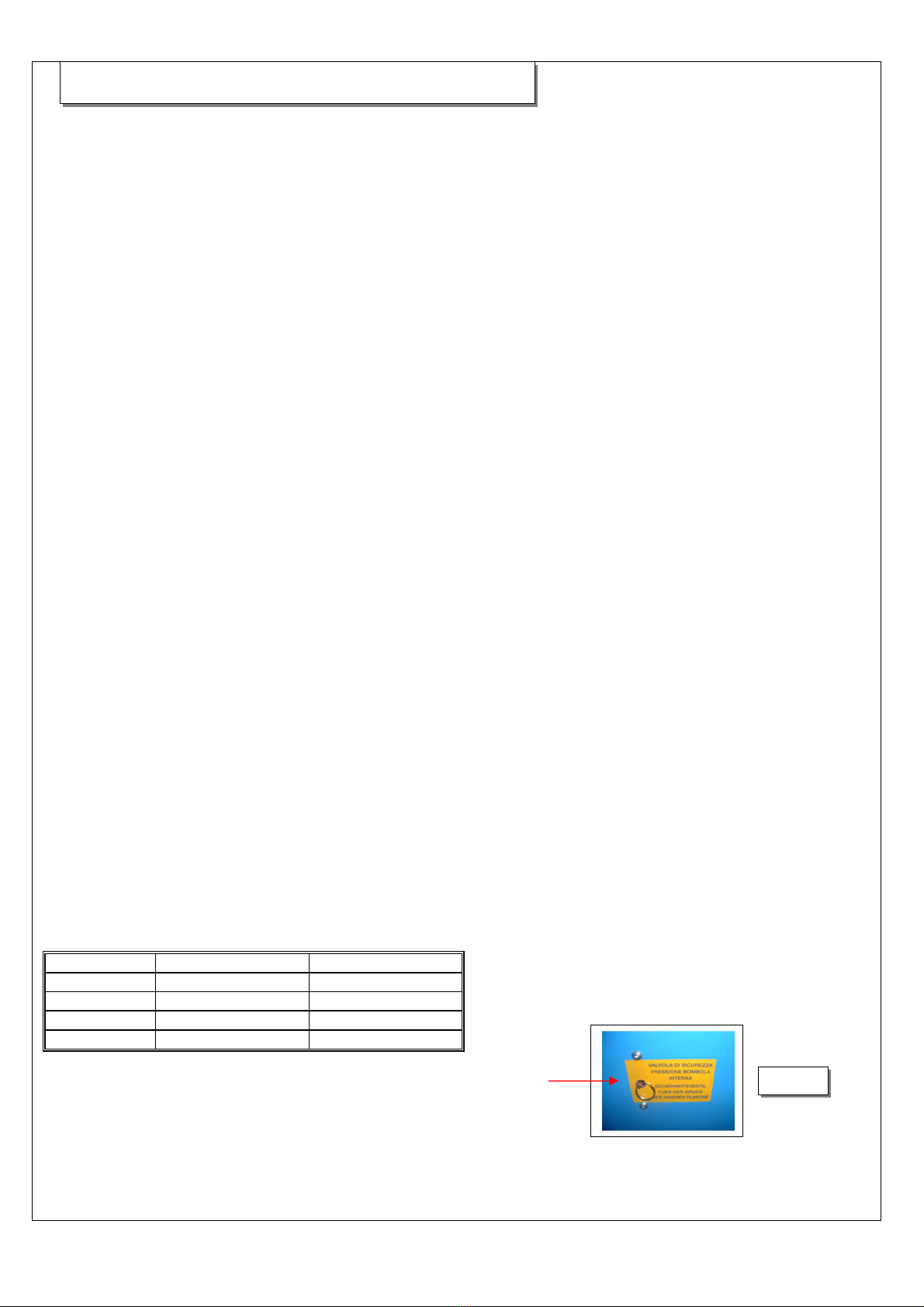
The inte nal bottle is supplied with a mechanic secu ity valve, which opens automatically, when the p essu e ises ove
16 ba . A second, bette eachable valve is positioned at the side of the small oil discha ge bottle.
6.1 PRESSURE TEST OF PLANT A/C
- The two high- and low p essu e cocks need o be closed.
- P ess the key “C” on the keyboa d.
- Sta t the vehicle in gea of 1500 .p.m.
- Switch-on the A/C device.
- Cont ol the p essu e on the gauges “A” and “B” acco ding to the following list:
T. su ounding LOW PRESSURE HIGH PRESSURE
°C 15 0,5 – 2,0 7,5 - 13
°C 20 0,5 – 2,5 10 - 16
°C 25 0,5 – 2,5 12 - 18
°C 30 0,5 - 3 12 - 20
CHAP. 6 USE F THE CENTRAL UNIT
Fig.
12

11
6.2 MANUAL
F om the base menu p ess the key “ENTER”, like that you can ente into the submenu, which contains the
following pa amete :
RECOVERY, VACUUM, OIL INJECTION, CHARGING;
RECOVERY (manual);
Fo the pe fo mance of the ecove y of f eon p ess the key “ENTER” afte the choice “Recove y”. If the plant
is empty (PRESSURE ZERO), the message “Attention 7 plant empty, cont ol whethe the cocks of the station
and the quick couplings a e open“ will appea .
At the p esence of f eon the ecove y will be pe fo med within the A/C plant; at the end the ecove y will be
pe fo med by the station automatically the discha ge of the old oil. To inte upt p ess key “C”.
VACUUM (manual);
Fo the pe fo mance of the vacuum the plant has to be emptied (P essu e unde o equal ze o), othe wise the
message ERR 5 Plant unde p essu e appea s;
P ess the key “ENTER” afte the choice “VACUUM”;
P og am the vacuum time with the a ow keys “+”o “-” ; it is possible to p og am a time between 1 and 180
minutes;
Confi m the p og ammed time with the “ENTER”- key;
On the display the message “test” will appea , like this it is possible to p og am the du ation of the leak test
between 0 and 30 minutes; via inse tion „0“ the leak test will not be executed.
Confi m the choice with the key “ENTER”, like that the vacuum phase will begin;
Afte ending of the vacuum phase the leak test will be pe fo med (if p og ammed p elimina y).
If leaks a e p esent within the A/C plant, the display will show the message “ERR 2 – Density of vacuum
insufficient”; in this case you need to sea ch fo possible leaks with the help of the leak detecto o t he
elect onic leak sea ch device (accesso ies on equest). P ess „C“ to exit.
If no leaks a e p esent, the display will again show the amount of f eon in the bottle. If du ing the vacuum
phase occu s a ise of p essu e (0,5 ba ), the station is automatically switching-off and the message „ERR 5“
appea s on the display. In this case pe fo m a ecove y befo e continuing.
OIL INJECTION (Manual);
The injection of oil into the A/C station can only be pe fo med, if the plant is in unde p essu e and this means
afte the vacuum phase. Fo the cha ge of oil into the plant, p ess the key “ENTER” afte the choice “OIL
INJECTION”; P og am the amount of oil to be inse ted into the plant with the a ow keys and confi m with
key “ENTER”; At the end of the pe fo mance the display shows the amount of f eon p esent in the bottle. It is
possible to mix the oil befo ehand within the containe with an additive, which is integ ated within the
leaksea che (on equest) in o de to emphasize possible existing leaks.
CHARGING OF FREON (manual);
To pe fo m the cha ge of f eon into the A/C plant (as usual with the plant in low p essu e), p ess the key
“ENTER” afte the choice “CHARGING”;
P og am the amount of gas, which is supposed to be loaded into the plant with the a ow keys “+” o “-”, P ess
the key “ENTER” to confi m;
Like that sta ts the cha ging of the plant A/C.
PLEASE NOTE: the loading will be pe fo med simultaneously via high- and low p essu e, if the p essu e in
the inne bottle is highe (ove 9 ba ), it is advisable to pe fo m the cha ging only ove the high p essu e (also
only pa tially), by closing the low p essu e cock.
At the end of the cha ging of the station a sequence of beeps will esound f om the station and the display will
show the amount of gas loaded into the plan.
If du ing the p og amming of the cha ge appea s “ERR1 – Gas in bottle insufficient” , you ne
ed to ecove gas
f om an exte nal bottle (see pa . 6.0) befo e you continue. The message ERR1, will be shown du ing the
p og amming, if the diffe ence between the necessa y and the eally p esent f eon in the bottle lies unde 1 kg.
P ess the key „C“ to exit.

12
6.3 HALF AUTOMATIC
With the p og am “half automatic”, it is automatically possible to pe fo m the following phases: - Recove y –
Oil discha ge – Vacuum – vacuum test;
Choose f om the main menu “half automatic” and confi m with “ENTER”;
- The display shows: “vacuum time”;
- P og am with the a ow keys “+”and “-” the vacuum time, it is possible to p og am a time between 1
and 180 minutes
- Confi m the p og ammed time with the key “ENTER”;
- The display shows “Vacuum test”;
- P og am the du ation of the vacuum test with the a ow keys “+” and “-„; it is possible to p og am the
du ation of the test between 0-30 minutes; inse tion of „0“, the leak test will not be pe fo med;
- Confi m the choice with key “ENTER”;
The station ca ies-out automatically the following Steps:
Fi st ecove y – 2 minutes pause – second ecove y – oil discha ge – vacuum – leak test (if p og ammed); if
leaks have come up, the display will show the message „oil injection“;
- P og am the amount of oil with the a ow keys “+ and –“ (if you inse t “0” of oil, the oil cha ge will
not be executed);
- Confi m the choice with key “ENTER”;
- P og am the amount of gas to cha ge with the a ow keys “+ and –“, confi m the choice with the key
“ENTER”.
Please no e: he charging wi h be performed simul aneously via high- and low pressure, if he pressure
wi hin he in ernal bo le is increased (over 9 bar), i is advisable o perform he charging only via he
high pressure (also only par ial), by closing he low pressure cocks..
Then pe fo m the p essu e tests (see pa . 6.1), sepa ate the connections of the A/C station and pe fo m a
manual ecove y by discha ging of the p essu e out of the tubes.
If leaks a e p esent within the A/C plant (only if p evious the leak test has been p og ammed), the display
shows the message “ERR 2 – Vacuum density insufficient“; in this case possible leaks have to be t aced with
the help of a leak sea ch lamp o an elect onic leak detecto (accesso ies on equest). P ess „C“ to exit.
If du ing the p og amming of the cha ge the fault “ERR1 – insufficient gas in the bottle” occu s, you need to
ecove gas f om an exte nal bottle befo e continuing (see pa . 6.0). The message ERR 1 will be shown du ing
the p og amming when the diffe ence between the necessa y and the eally p esent f eon in the bottle is less
than 1 kg. P ess “C” to exit.
A en ion: It is possible to p int out the pe fo med steps by p essing the key “ente ” fo 2 seconds (on the
display appea s “p intig”), o the key “p int” on the p inte , always afte having p essed the key “C”.
PLEASE NOTE THAT if du ing the oil discha ge an inc ease of the p essu e occu s (> 0,5 ba ), the station
automatically continuous with the ecove y phase.
PLEASE NOTE THAT if an inc ease of p essu e occu s du ing the vacuum phase (> 0,5 ba ), the station
switches off and the message E o 5 appea s on the display. In this case pe fo m a ecove y befo e continuing.

13
6.4 AUTOMATC
With the p og am “automatic”, it is possible to execute all phases automatically (f om the ecove y to the
cha ge); Ensu e that the station has a sufficient amount of f eon befo e switching-on the station in o de to
function p ope ly, othe wise pe fo m a ecove y as mentioned in pa . 6.0.
F om the main menu p essing the a ow key “+ “ the following steps will be shown:
MANUAL; 2.HALF AUTOMATIC; 3.AUTOMATIC; 4.DATA BASE; 5.UTILITY; Retu n to the amount of
gas, which is within the bottle;
- Choose “automatic” with the keys “+ and –“ and p ess “ENTER”;
- The display shows the message “Vacuum”;
- P og am the vacuum time with the keys “+ and –“; confi m with “ENTER”;
- the display shows “vacuum test”;
- P og am the du ation of the test with the keys “+ and –“ and confi m with ENTER”; by p essing of „0”
the vacuum test will not be executed;
- The display shows “oil injection”;
- P og am with the a ow keys “+ and –“ and confi m with key “ENTER”; by the p og amming of “0”
the oil filling will not be executed;
- The display shows “gas cha ging”;
- P og am with the a ow keys “+ and –“ and confi m with key ”ENTER”;
- The station will pe fo m all phases automatically;
FOR THE PRINT-OUT OF DATA (only in p inte ve sion):
- At the end of the cycle p ess the key “C”;
- P ess “p int” on the p inte (see pa . 7);
Attention: If you like to inte upt the phases the data will not be memo ized and the efo e will not be p inted.
Ca y out the p essu e cont ol (see pa . 6.1), sepa ate the connecto s f om the plant A/C and pe fo m a manual
ecove y by eleasing the p essu e f om the tubes.
If leaks occu within the plant (only if p eviously a leak test has been p og ammed), the display will show the
message “E o 2 – Vacuum density insufficient“; in this case a possible leak has to be sea ched by using a
leak sea ch lamp o an elect onic leak detecto (accesso ies on equest). P ess „C“ to exit.
PLEASE NOTE If du ing the p og amming of the cha ging the message “E o 1 – Gas in bottle
insufficient” occu s, you have to ecove fi st gas f om an exte nal bottle befo e continuing (see pa . 6.0). The
message E o 1, will be shown du ing the p og amming, if the diffe ence between the necessa y and the eally
p esent f eon in the bottle is less than 1 kg. P ess „C“ to exit.
PLEASE NOTE If du ing the oil discha ge an inc ease of p essu e (> 0,5ba ) occu s, the station will ca y-on
automatically with the ecove y phase.
PLEASE NOTE if a p essu e inc ease (
> 0,5 ba )
occu s du ing the vacuum phase, the station switches-
off and
the message E o 5 appea s on the display. In this case pe fo m a ecove y befo e continuing.

14
6.5 DATA BANK (personalized – vehicles)
With the pe sonalized data bank it is possible to memo ize 30 vehicles and to give them an app op iate
numbe ; like that it is possible to pe fo m all phases by simply calling the app op iate vehicle numbe ;
Fo execution p ess the key “ENTER” afte you have chosen “data base” f om the main menu;
the display shows “p og am choice”; while p essing of one of the two a ow keys the display shows “Setting”;
With “Setting” you p og am the data banks, with “choose p og amms” you ecall the memo ized data.
“INSERT”:
- P ess “ENTER”, the fi st numbe above on the ight (memo ized numbe ) illuminates;
- Choose the memo y numbe , which you like to p og am (f om 1-30) via the a ow keys (von 1 bis 30);
- Confi m with “ENTER”;
- The fi st ciphe above left illuminates (du ation of vacuum time);
- P og am the equi ed vacuum time with the a ow keys and confi m with “ENTER”;
- that illuminates automatically the second ciphe ;
- P og am the du ation of the vacuum test and confi m with “ENTER”, by p essing of “0”, the vacuum test
will not be pe fo med;
- P og am the amount of f esh oil, which should be inse ted within the plant with the a ow keys and confi m
with key „ENTER”;
- p og am at the end the amount of gas to be inse ted within the plant and confi m with “ENTER”;
Repeat the same steps to memo ize the othe positions of the data bank;
CHOICE OF DATA BANKS MEMORIZED:
Fo the choice of the memo ized positions of the data bank, choose “Choice p og ams” and confi m with the
key “ENTER”;
- the numbe above ight illuminates;
- Choose with the a ow keys “+ and –“ the numbe of the data bank acco ding to the ca ’s sign of the ca
which should be cha ged;
- The display shows (f om sx to dx): vacuum time - du ation vacuum test- amount of oil – amount of gas;
Confi m with key “ENTER”, like that all phases a e being ca ied out automatically.
Da abase vehicles
- to p oceed p ess the key “ENTER” afte having selected “data bank vehicle” f om the menu;
- choose the ca manufactu e with the keys “+” and “-“ and confi m with “Ente ”;
- choose the p esent model with the keys “+” and “-“ and confi m with “Ente ”;
- the display will show the pa amete s in memo y
- confi m with the key “Ente ”;
- now the whole automatic cycle will be pe fo med.

15
6.6 UTILITY
With the p og am “Using”, it is possible to pe fo m the following steps: gas echa ge – calib ation test-
measu e unit – language – p inte heading- se vice
Recha ge GAS
See Chap. 6.0
CALIBRATION TEST
Choose “Calib ation test” and confi m with key “ENTER”, on the display appea s the weight of the gas in the
bottle and the coefficient of the cell. While putting the sample weight on the bottle, one can exactly ead the
total weight f om the display; the displays shows simila ly the coefficient of the cell (fo technical se vice).
MEASURE UNIT
It is possible to display the measu ing unit in kg o pound;
Choose the “Measu ing unit” and p ess the key “ENTER”;
Choose with the a ow keys the desi ed measu ing unit and confi m with the key “ENTER”.
LANGUAGE
Confi m with „Ente “ and choose with the a ow keys the equested language (italian-english-f ench-ge man,
to confi m the choice p ess „Ente “
PRINTER HEADING (is fo P inte ve sion)
1) Select “p inte heading” and push the ENTER key ;
2) The display shows “R1” (line no.);
3) Push the “ENTER” key, the fi st cha acte will blink (o the fi st line);
4) With the a ow keys (+ and -) it is possible to select the equested cha acte (numbe s-symbols-capital
lette s-small lette s- space);
5) Confi m you choice with the “ENTER” key;
6) Next cha acte will automatically blink;
7) Repeat the p ocedu e f om the step no. 4;
8) With the setting of the 24th cha acte you will skip to the second line;
9) If you want to jump the line push “+” while any cha acte o any line is blinking;
10) Set data as pe the step no. 3;
11) Once set the 9th line push “ENTER” until the display will show again the message “p inte heading”;
The heading is in this way memo ized
TECHNICAL SERVICE (ONLY FOR THE TECHNICAL SERVICE)
Inse t the pass wo d in o de to pe fo m the calib ation of the scale.
7.0 HEATING INTERNAL BOTTLE
The heating of the bottle, with the following p essu e ise, favou s the cha ge of f eon into the A/C plant in the
cool season of the yea (with a bottle p essu e < than 5-6 ba ). The switch-on of the heating is being pe fo med
automatically.
P inte (optional)

16
To maintain the station with full efficiency it is necessa y to pe fo m egula maintenances.
The disrespect of performing the maintenances from the customers side frees the producer
From every responsibility concerning the guarantee.
All maintenance wo ks have to be pe fo med afte the sepa ation of the station f om the net. Replace the d ie
filte and the oil of the pump egula ly (acco ding to the use) and clean the de-oiling filte as well. The display
will then show the message „Attention 9“, fo the pe fo mance of the maintenance of the station afte 150
hou s of functioning of the comp esso .
Pump oil
Replace the pump oil eve y 100/150 hou s of functioning o at least eve y 2 yea s even when the station is not
continuously in use. The exchange of oil is absolutely necessa y even when the p esence of polluting
substances can cause cloudiness, in this
case this can cause i eve sible damages on the mechanical pa ts of the
pump. Use only mine al oil fo vacuum pumps type AV68I.
The amount is app ox. 300 g am.
Oil refill
1) Fill the new oil into the cap “b”, until you each the height of the app op iate glass.
Exchange of pump oil
1) Discha ge the oil f om the cap “a”.
2) Inse t the new oil via the cap “b”, until you each the height of the app op iate visualizing glass “c”.
Attention: Do not dispose of the oil via normal waste but via special waste according to the law. Cod. Oil
exchange: AV68I
CHAP. 7 REGULAR MAINTENANCE
Fig. 13
b
a
c

17
Exchange of drier fil er
.
Exchange the d ie filte eve y 100/150 wo king hou s of the ecove y comp esso o at least eve y 2 yea s
even when the station is not in continuous use.
1) Sepa ate the ea panel f om the station.
2) Unsc ew the filte slowly and ca efully.
3) Install the new filte (in conside ing of the
di ection).
Attention: Do not dispose of the filter with normal waste but with special waste according to the law.
A t. Exchange of de-oiling filte
Main enance of oil discharging fil er.
The oil-discha ging filte has to be cleaned eve y time the d ye filte is exchanged.
1) Sepa ate the ea panel f om the station.
2) Unsc ew the filte and clean the inne etina.
Fig.16 oil-discha ging filte
Fig.14

18
In o de to solve p oblems please keep exactly to the secu ity no ms mentioned in Chap 1.
PROBLEM Solving
The station does not switch-on;
The main switch does not
illuminate.
Cont ol the secu ity of the mounted line on the switch-on block.
At switch-on the display emains
switched-off; the main switch does
not glow
1) Cont ol the cabling on the switch boa d display.
2) possible default: powe supply – switchboa d CPU
Call the technician.
The display shows a completely
false amount of gas within the
bottle.
1) Cont ol the tightening of the sc ews of the balance senso ;
2) Calib ate the balance (chap. 6.6 technical se vice);
Call the technician.
The ecove y sta ts but no gas is
being ecove ed.
Possible default:
1) Comp esso ;
Call the technician.
The station is blocked in the
ecove y phase;
The high and low p essu e gauges
a e on ze o;
1) Calib ate if possible the p essu e cont ol.
The station finishes the ecove y
phase but the high- and low
p essu e gauge show the p esence
of gas (> ze o).
1) Calib ate if possible the p essu e cont ol.
The station is blocked in the
ecove y phase;
The high- and low p essu e gauges
a e unde p essu e.
Close the cock within the bottle:
1) The station finishes the ecove y phase (gauge on ze o):
Elect o-cha ging valve EV2 blocked.
2) The station emains fu the mo e within the ecove y phase:
Possible default: Comp esso A t OMT021CR000.
Call the technician.
The cha ging phase sta ts but the
gas does not come out of the
Station;
The high and low p essu e gauges
emain on ze o.
Possible default:
One-Way-Valve of cha ging (afte the elect o valve) A t.
0RR026CR000.
Call the technician.
Smoke comes out of the pump in
the vacuum phase; the sound of the
pump is not no mal/ egula .
Possible suction of ai ;
1) Close the cock of the station and t y anew, whethe the pump is
sta ting its function, cont ol the joints of the tubes and connecto s.
2) Cont ol the oil level of the pump.
The display shows eve ERR2
du ing the leak test.
1) close the cocks and t y to pe fo m a vacuum fo 5 minutes, if no
leaks a e signalized, cont ol the joints of the tubes and the quick
couplings.
2) Should the p oblem pe sist call the technician.
When no f esh oil is being cha ged
into the A/C station.
1) Cont ol the integ ity of the f esh oil tank.
2) Call the technician.
CHAP. 8 Suggestions to solve functioning problems

19
MENU’
OVERVIEW OVER THE FUNCTIONS “main menus and Under menus”
This ove view allow a quick localization of a ce tain function coming f om the main menu.
Main menu
1.Manual - 2.Half automatic - 3.Automatic- 4.Data banks - 5.Usage – available Gas amount
ecove y, Vacuum, oil injection, cha ging
Phase 1: f om the ecove y to the leak test
Phase 2: oil injection-cha ging
single phase :
f om the ecove y to the cha ging
Choice p og ams – inse tion
echa ge gas, calib ation test ,
measu ing unit,
language, technical se vice
Available within the main menu and on
switch-on o the p essing of key
“c” to exit.

20
The device has a gua antee pe iod of 12 months f om the date of delive y. Within the gua antee the comp esso
and the vacuum pump is not included, because it can occu , that the comp esso is being t eated with a diffe ent
oil than the ecommended one.
CAP. 9 GUARANTEE
Other manuals for OK CLIMA
1
Table of contents
Popular Test Equipment manuals by other brands

Wiha
Wiha 45217 instruction manual

Keysight Technologies
Keysight Technologies N4000A SNS Series Operating and service manual

Keysight Technologies
Keysight Technologies U3042AE08 User's and service guide

Fluke
Fluke 712B/EN user manual

Rohde & Schwarz
Rohde & Schwarz 802.2020.52 Service manual

Tektronix
Tektronix 7603 manual