Hioki IM9201 User manual

EN
Instruction Manual
IM9201
SMD TEST FIXTURE
July 2016 Edition 1
IM9201A961-00 16-07H


1
Introduction
Introduction
Thank you for purchasing the Hioki IM9021 SMD Test Fixture. To obtain maximum performance
from the device, please read this manual rst, and keep it handy for future reference.
This device is used by connecting to the impedance analyzer. Before using the impedance
analyzer, read the instruction manual of the impedance analyzer carefully.
Contents
Verifying Package Contents p.2
Safety Information p.3
Operating Precautions p.4
Product Overview p.5
Names and Functions of Parts p.6
Measuring Method p.7
■Measurement Procedure p.7
■Inspection Before Use p.8
■Attaching the Test Head and the Adapter p.9
■Calibration p.10
■Attaching the Device p.13
■Electrical Length Correction p.14
■Short Correction p.15
■Open Correction p.18
■Starting the Measurement p.20
Specications p.21
Maintenance and Service p.22
IM9201A961-00
9
8
7
6
5
4
3
2
1
Appx. Index

2
Verifying Package Contents
When you receive the device, inspect it carefully to ensure that no damage occurred during
shipping. In particular, check the accessories. If damage is evident, or if it fails to operate according
to the specications, contact your authorized Hioki distributor or reseller.
Conrm that the following items are provided.
(1)
(3) (4)
(5) (11)(2)
(9)(8)(10)(7)
(6)
Model IM9201 SMD Test Fixture × 1..............................................................................(1)
Short plate × 5................................................................................................................
GND plate × 1
Device guide × 1
(2)
Hexagon socket head bolts (spare, M1.4 × 4 mm) × 4...................................................
Knob (for xing tip pin) × 1
Tip pin × 2
(3)
Brush for cleaning × 1 ....................................................................................................(4)
Hex driver × 1.................................................................................................................(5)
Carrying case × 1...........................................................................................................(6)
Instruction Manual × 1
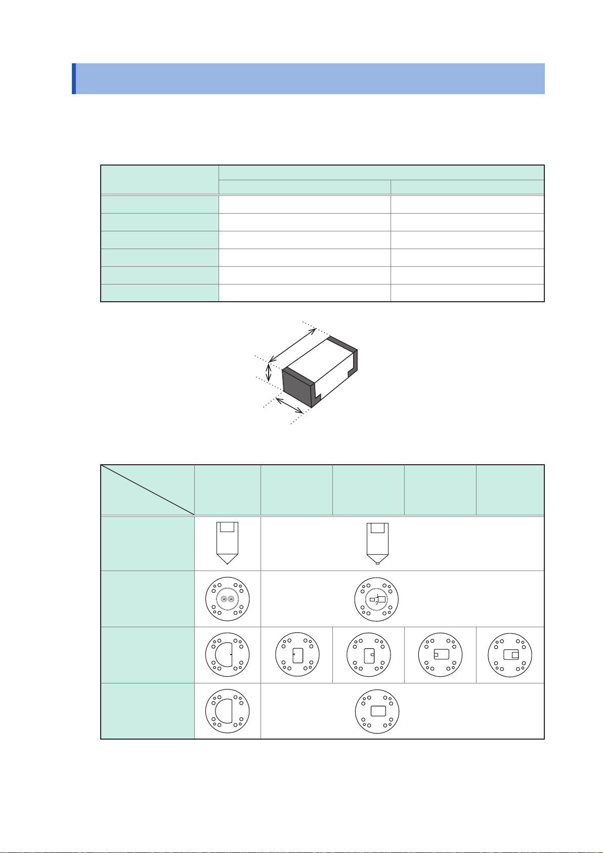
GND plate and device guide for the sizes 1005 (0402), 1608 (0603), 2012 (0805), 3216 (1206), 3225 (1210)
are installed in the device. Refer to "Tip pins, device guides, and plates for each DUT size" (p.5).
Options (sold separately)
Model IM9906 Adapter (3.5 mm/7 mm)..........................................................................(7)
Model IM9905 Calibration Kit (LOAD)............................................................................(8)
Model IM9905 Calibration Kit (OPEN)............................................................................(9)
Model IM9905 Calibration Kit (SHORT) .........................................................................(10)
Magnifying glass (Model IM9200 Test Fixture Stand accessory) ...................................(11)
Model IM9200 Test Fixture Stand
Options (sold separately) can be stored inside (7) to (11) of the carrying case. Please store them after
removing the packed sponge at the time of unpacking.

3
Safety Information
Safety Information
Before using the device, be certain to carefully read the following safety notes.
CAUTION
•Mishandling during use could result in damage to the device. Be certain that you
understand the instructions and precautions in the manual before use.
• Individuals using an electrical measuring device for the rst time should be supervised
by a technician who has experience in electrical measurement.
Notation
In this document, the risk seriousness and the hazard levels are classied as follows.
WARNING Indicates a potentially hazardous situation that may result in death
or serious injury to the operator.
CAUTION Indicates a potentially hazardous situation that may result in minor
or moderate injury to the operator or damage to the device or
malfunction of the device.
IMPORTANT Indicates information related to the operation of the device or
maintenance tasks with which the operators must be fully familiar.
Indicates prohibited action.
Indicates the action which must be performed.
Symbols for standards
Indicates the Waste Electrical and Electronic Equipment Directive (WEEE Directive)
in EU member states.
Indicates that the product conforms to regulations set out by the EC Directive.
9
8
7
6
5
4
3
2
1
Appx. Index

4
Operating Precautions
Follow these precautions to ensure safe operation and to obtain the full benets of the various
functions.
Installation Environment
WARNING
Installing the device in inappropriate locations may cause malfunctions or may
give rise to accidents. Avoid the following locations:
•Exposed to direct sunlight or high temperature
•Exposed to corrosive or combustible gases
•Exposed to strong electromagnetic elds or electrostatic charges
•Near induction heating systems (such as high-frequency induction heating
systems and IH cooking equipment)
•Susceptible to mechanical vibration
•Exposed to water, oil, chemicals, or solvents
•Exposed to high humidity and condensation
•Exposed to high quantities of dust particles
Handling the Device
CAUTION
• Do not press the tip pin in the electrode when the DUT is not attached.
• While pressing the tip pin into the DUT, the DUT may pop out. To avoid injuries, lower
the pusher slowly and press the tip pin into the DUT.
• To avoid damage to the device, protect it from physical shock when transporting and
handling. Be especially careful to avoid physical shock from dropping.
•To prevent damage to the device, use the bolts included in the factory shipment for
securing the pusher and plate. If you have lost any bolts or nd any damaged bolts,
please contact your authorized Hioki distributor or reseller for a replacement.
Measurements
CAUTION
•Do not input a voltage in excess of the maximum applied voltage listed in the
specications. It may cause damage to the device or connecting equipments.
•To avoid damage, do not connect the charged capacitor to the device.
Precautions during shipment
During shipment of the device, handle it carefully so that it is not damaged due to a vibration or
shock.

5
Product Overview
Product Overview
This device is the test xture for SMD (Surface Mount Device) to be used by connecting to the
impedance analyzer of Hioki. It measures the 2 terminals of SMD.
Measurable DUT size
Nominal size [mm]
JIS (EIA) Dimensions
L × W [mm] H [mm]
0603 (0201) (0.6±0.03) × (0.3±0.03) H ≥ 0.25
1005 (0402) (1.0±0.1) × (0.5±0.1) H ≥ 0.4
1608 (0603) (1.6±0.15) × (0.8±0.15) H ≥ 0.4
2012 (0805) (2.0±0.15) × (1.2±0.15) H ≥ 0.4
3216 (1206) (3.2±0.15) × (1.6±0.15) H ≥ 0.4
3225 (1210) (3.2±0.15) × (2.5±0.15) H ≥ 0.4
L
W
H
Tip pins, device guides, and plates for each DUT size
DUT size
JIS (EIA)
Accessories
0603 (0201) 1005 (0402) 1608 (0603) 2012 (0805) 3216 (1206)
3225 (1210)
Tip pin
0603
3225
3216
1005 1608
2012
0603
3225
3216
1005 1608
2012
(Common)
Device guide
0603
3225
3216
1005 1608
2012
0603
3225
3216
1005 1608
2012
(Common)
Short plate
(At the time of
short correction)
0603
3225
3216
1005 1608
2012
0603
3225
3216
1005 1608
2012
0603
3225
3216
1005 1608
2012
0603
3225
3216
1005 1608
2012
0603
3225
3216
1005 1608
2012
GND plate
(At the time of open
correction and
measurement)
0603
3225
3216
1005 1608
2012
0603
3225
3216
1005 1608
2012
(Common)
9
8
7
6
5
4
3
2
1
Appx. Index

6
Names and Functions of Parts
(2)
(1)
(3)
(4)
(5)
(6)
(12)
(9)
(11)
(11)
(7)
(8)
(13)
(10)
(1) Pusher Presses and xes the DUT.
(2) Tip pin The tip of the pusher. Replaced according to the DUT to be measured.
(3) Shock absorber Absorbs the shock when the pusher comes down.
(4) Device guide Placed on the top of the GND plate or short plate for use.
(5) Short plate or
GND plate Short plate is used at the time of short correction.
GND plate is used at the time of open correction and measurement.
(6) Electrode section The measurement unit of the device. Measures by placing the GND plate
and DUT on top of the electrode.
(7) Model IM9906 Adapter
(3.5 mm/7 mm) The exclusive adapter for connecting the device to the test head of the
impedance analyzer side.
(8) Test head The test head is provided with the impedance analyzer.
(9) Loupe The magnifying glass provided with the model IM9200 Test Fixture Stand
(option). It is used by installing to the model IM9200.
(10) Knob The knob is loosened to move the tip pin to the DUT location. Then the
knob is tightened to x it.
(11) Stand xing knob The knob xes the device to the model IM9200 Test Fixture Stand.
(12) Stopper Locks the pusher so that it does not come down.
(13) Model IM9200 Test
Fixture Stand The exclusive stand for xing the test head of the impedance analyzer and
the device.

7
Measuring Method
Measuring Method
Measurement Procedure
You will need (besides the device and accessories):
•Model IM7580 series Impedance Analyzer × 1
•Model IM9200 Test Fixture Stand × 1
•Model IM9906 Adapter × 1
• 3.5 mm Connector torque wrench × 1 (This is not provided with the device.)
• Tweezers × 1 (This is not provided with the device. Tweezers which are thinner than the DUT
size, clean, and not magnetized are recommended.)
1
Connect the test head to the
impedance analyzer. Connect the cable of the test head to the impedance analyzer.
See the instruction manual
of the impedance analyzer. Test head
2
Attach the test head and adapter
to the stand. Attach the test head and model IM9906 Adapter to the model
IM9200 Test Fixture Stand.
Model IM9200
Model IM9906
(p.9)
3
Execute the calibration. Execute the open calibration, short calibration, and load
calibration.
(p.10)
4
Attach the device. Attach the device to the model IM9200 Test Fixture Stand.
Device (model IM9201)
(p.13)
5
Execute the correction. Execute the electrical length correction, short correction, and
open correction.
(From p.14)
6
Start the measurement. Connect the DUT to the measurement location of the device
guide and start the measurement by the impedance analyzer.
(p.20)
9
8
7
6
5
4
3
2
1
Appx. Index

8
Measuring Method
Inspection Before Use
Before using the device, verify that it operates normally to ensure that no damage occurred during
storage or shipping. If you nd any damage, contact your authorized Hioki distributor or reseller.
Inspection item Solution
Is the short plate worn? Compare the resistance value with the new or a non-defective short
plate. Replace with new short plate if the resistance value is high.
Is the tip pin deformed? If the tip pin is deformed, contact your authorized Hioki distributor or
reseller.
Is the device damaged? If the device is damaged, send it for repair.
Is the GND plate damaged or
worn? If there are signicant scratches and deformation, replace it with the
new GND plate.

9
Measuring Method
Attaching the Test Head and the Adapter
Attach the test head and model IM9906 Adapter to the model IM9200 Test Fixture Stand.
IMPORTANT
The impedance analyzer, test head, and measurement cable are adjusted together at the time
of shipment. Use the test head and measurement cable included along with the impedance
analyzer. Conrm that the serial no. of the impedance analyzer and test head is same.
You will need:
•Test head × 1
•Model IM9200 Test Fixture Stand × 1
•Model IM9906 Adapter × 1
• 3.5 mm Connector torque wrench × 1 (This is not provided with the device.)
Test head
Model IM9200
1
2
Metal ttings
1
Pull the metal ttings to the model IM9200 Test
Fixture Stand side.
2
Place the test head on the stand and tighten the
knob.
Model IM9906
Notch
Measuring
terminal
3
4
3
Place the notch of the model IM9906 Adapter
parallel to the metal ttings, then install onto the
measurement terminal of the test head.
At this time it is stopped temporarily. Position the notch of the
model IM9906 Adapter where the metal ttings can slide.
4
Fix the notch of model IM9906 adapter by sliding
the metal ttings.
3.5 mm connector
nut
5
5
Tighten the nut of the 3.5 mm connector by using a
torque wrench.
Recommended torque: 0.9 N·m
Tightening the nut until the handle of the wrench bends
slightly is sufcient. Do not over tighten.
9
8
7
6
5
4
3
2
1
Appx. Index

10
Measuring Method
Calibration
Connect the three standard units, open, short, and load of the model IM9905 Calibration Kit to the
reference surface (terminal) of model IM9906 Adapter one by one, and measure the respective
calibration data. This reference surface is referred to as the “calibration reference surface”. The
cause of errors between the impedance analyzer itself and the calibration reference surface is
eliminated.
The dened value differs according to the calibration kit to be used. See the instruction manual of
the impedance analyzer for the input method of the dened value to the impedance analyzer.
CAUTION
While attaching and detaching the calibration kit, make sure that the internal conductor
of the calibration kit does not rotate. If the internal conductor rotates, it may cause
damage to the electrode.
When the calibration cannot be executed:
• Conrm that the calibration kit and model IM9906 Adapter are connected properly.
•Check that the DC measurement limit value of the impedance analyzer is appropriate.
• Connect the model IM9906 adapter, calibration kit and this device with a 7 mm connector.
Recommended torque for the 7 mm connector is 1.35 N·m.
You will need:
Model IM9905 Calibration Kit (OPEN, SHORT, and LOAD) × 1 of each
1
Set the measurement conditions like frequency,
measurement signal level, and measurement speed
in the impedance analyzer.
For model IM9905 Calibration Kit
Dened values:
OPEN G: 0 S, Cp: 82 fF
SHORT Rs: 0 Ω, Ls: 0 H
LOAD Rs: 50 Ω, Ls: 0 H
Offset delay:
OPEN 0 s
SHORT 0 s
LOAD 0 s
2
Set the dened values of the calibration kit and offset
delay in the impedance analyzer.
The initial values of the impedance analyzer are set to the
values of the left-side table.
Nut
Bolt thread
3
3
Raise the bolt thread by turning the nut of model
IM9906 Adapter.

11
Measuring Method
Nut
5
Open
calibration kit
4
Place the open calibration kit on the reference
surface.
5
As shown in gure, connect by turning only the nut
of open calibration kit while pressing the convex
portion on the top part of the open calibration kit.
The convex part of the open calibration kit is connected with
the internal conductor. If the calibration kit is rotated without
pressing the convex part, the internal conductors of calibration
kit and adapter may graze each other, and the calibration kit
and adapter may get damaged.
6
Execute open calibration by using the impedance
analyzer.
2
1
3
4
Nut
7
Short
calibration kit
9
7
Remove the open calibration kit by turning the nut of
the open calibration kit.
8
Place the short calibration kit on the reference
surface.
9
As shown in gure, connect by turning only the nut
of short calibration kit while pressing the convex
portion on the top part of the short calibration kit.
The convex part of the short calibration kit is connected with
the internal conductor. If the calibration kit is rotated without
pressing the convex part, the internal conductors of calibration
kit and adapter may graze each other, and the calibration kit
and adapter may get damaged.
10
Execute short calibration by using the impedance
analyzer.
2
1
3
4
9
8
7
6
5
4
3
2
1
Appx. Index

12
Measuring Method
11
Load
calibration kit
13
Nut
11
Remove the short calibration kit by turning the nut of
the open calibration kit.
12
Place the load calibration kit on the reference
surface.
13
As shown in gure, connect by turning only the nut
of load calibration kit while pressing the top part of
the load calibration kit.
If the top part of the load calibration kit is rotated, the internal
conductors of the calibration kit and adapter may graze each
other, and the calibration kit and adapter may get damaged.
14
Execute load calibration by using the impedance
analyzer.
2
1
3
4
15
Remove the load calibration kit by turning the nut of
the load calibration kit.

13
Measuring Method
Attaching the Device
Attach the device to the model IM9200 Test Fixture Stand and adapter.
Nut
Bolt thread
1
1
Lower the bolt thread by turning the nut of model
IM9906 Adapter.
3
2
2
2
Loosen the stand xing knob.
3
Place the device on the model IM9200 Test Fixture
Stand.
As shown in gure, slide the notch part.
4
5
5
4
Turn the nut of model IM9906 Adapter and connect to
the device.
5
Tighten the stand xing knob.
9
8
7
6
5
4
3
2
1
Appx. Index

14
Measuring Method
Electrical Length Correction
The error, caused by the phase shift occurring between the calibration reference surface and the
measurement DUT's connection surface is compensated.
Set the electrical length correction to 19 mm in the impedance analyzer.
1
2
3

15
Measuring Method
Short Correction
Short correction is executed to reduce errors. The short plate is used.
CAUTION
• To avoid damage to the device and DUT, while pressing the tip pin into the DUT, move
the tip pin slowly so that shock is not applied.
• To avoid damage to the bolt xing the plates, insert the bolt vertically and tighten it
with appropriate force.
• To avoid injury, make sure that your hand is not in-between the pusher and tip pin.
IMPORTANT
Do not scratch the electrode, GND plate, and short plate of the device or touch them directly with
your hand. It may affect the measurement accuracy and reproducibility.
You will need:
•Hex driver × 1
• Tweezers × 1 (This is not provided with the device. Tweezers which are thinner than the DUT
size, clean, and not magnetized are recommended.)
•Device guide and short plate × 1 each
Device guides and short plates for each DUT size
The set direction as viewed from the front (position from where the model name IM9201 can be read).
DUT size
JIS (EIA)
Accessories
0603 (0201) 1005 (0402) 1608 (0603) 2012 (0805) 3225 (1210)
3216 (1206)
Device guide
0603
3225
3216
1005 1608
2012
0603
3225
3216
1005 1608
2012
0603
3225
3216
1005 1608
2012
0603
3225
3216
1005 1608
2012
0603
3225
3216
1005 1608
2012
Short plate
(At the time of
short correction)
0603
3225
3216
1005 1608
2012
0603
3225
3216
1005 1608
2012
0603
3225
3216
1005 1608
2012
0603
3225
3216
1005 1608
2012
0603
3225
3216
1005 1608
2012
9
8
7
6
5
4
3
2
1
Appx. Index

16
Measuring Method
1
For this device
OPEN G: 0 Ω, Cp: 0 F
SHORT Rs: 0 Ω, Ls: 0 H
1
Set the reference value of correction (COMPEN) in the
impedance analyzer.
The initial values of the impedance analyzer are set to the values
of the left-side table.
When measuring very small inductors, the short plate’s
inductance may affect measured values.
In such cases, enter the short plate’s inductance as the short
correction reference value.
Residual parameters (representative values)
Short plate’s inductance (at 3 GHz)
0603 (0201): 0.7 nH, 1005 (0402): 0.5 nH, 1608 (0603): 0.7 nH,
2012 (0805): 0.5 nH, 3225 (1210): 0.5 nH
By performing this correction process, you can eliminate the
inductance of the short plate from measurement results. However,
measurement error may increase due to variability in the short
plate’s inductance.
2
34
5
6
Short plate
2
Remove four bolts by using the hex driver.
3
Remove the device guide and GND plate.
The plate might be deformed if it is removed forcibly. Keep the
plate leveled so that load is not applied over it.
4
Place the central convex part of the short plate of the
DUT size to be measured facing upwards, then match
it with the measurement position and install it in the
electrode.
Cross-section diagram of short plate
5
Attach the device guide.
Match the frame of the DUT size to be measured with the
measurement location.
6
Tighten four bolts by using the hex driver.
Stopper Knob
Pusher
7
8
9
7
Loosen the knob, insert the tip pin according to the
DUT size into the tip of the pusher and tighten the knob
lightly.
8
Hold the pusher of the stopper side tightly.
9
Pull the stopper slowly.

17
Measuring Method
10
11
10
Lower the pusher slowly. Then turn the knob to adjust
the position of the tip pin to a position which can be
xed by the DUT.
11
When the location of tip pin is nalized, x it by turning
the knob and lower the pusher.
12
Execute short correction by using the impedance
analyzer.
When the correction cannot be executed:
• Conrm that the short calibration kit and model IM9906
Adapter are connected properly.
•Check that the DC measurement limit value of the
impedance analyzer is appropriate.
1
2
3456
9
8
7
6
5
4
3
2
1
Appx. Index

18
Measuring Method
Open Correction
Open correction is executed to reduce errors. The GND plate is used.
You will need:
•Hex driver × 1
• Tweezers × 1 (This is not provided with the device. Tweezers which are thinner than the DUT
size, clean, and not magnetized are recommended.)
•Device guide and GND plate × 1 of each
Device guides and GND plates for each DUT size
DUT size
JIS (EIA)
Accessories
0603 (0201) 1005 (0402) 1608 (0603) 2012 (0805) 3225 (1210)
3216 (1206)
Device guide
0603
3225
3216
1005 1608
2012
0603
3225
3216
1005 1608
2012
0603
3225
3216
1005 1608
2012
0603
3225
3216
1005 1608
2012
0603
3225
3216
1005 1608
2012
GND plate
(At the time of open
correction and
measurement)
0603
3225
3216
1005 1608
2012
0603
3225
3216
1005 1608
2012
0603
3225
3216
1005 1608
2012
0603
3225
3216
1005 1608
2012
0603
3225
3216
1005 1608
2012
1
23
4
5
GND plate
1
Remove four bolts by using the hex driver.
2
Remove the device guide and short plate.
The plate might get deformed if it is removed forcibly. Keep
the plate leveled so that load is not applied over it.
3
Attach the GND plate to the electrode.
The frame of DUT size to be measured should t the
measurement position.
4
Attach the device guide.
The frame of DUT size to be measured should t the
measurement position.
5
Tighten four bolts by using the hex driver.
66
Keep the pusher in a raised state.
Table of contents
Other Hioki Test Equipment manuals