Spintec I.C.C. User manual

I.C.C.
Individual Cell Charger
Users Manual
For Firmware Version 1.05

1
Index
1. Foreword............................................................................................ 2
2. Features of the ICC charger ............................................................ 3
3. Components....................................................................................... 4
4. Setting up the unit............................................................................. 5
4.1 Placement of the unit.................................................................... 5
4.2 Connecting to the power supply .................................................. 5
4.3 Inserting a pack in the ICC tray................................................... 5
4.4 Connecting a pack to the external output..................................... 8
4.5 Connecting a motor to the external output................................... 8
5. Menu structure navigation using the Spinclick dial...................... 8
5.1 Start up ......................................................................................... 8
5.2 Main menu ................................................................................... 9
5.2.1. ICC charging......................................................................... 9
5.2.2. ICC discharging................................................................... 12
5.2.3. External Output................................................................... 13
5.2.4. System Settings................................................................... 14
6. Charging recommendations........................................................... 15
7. Error messages................................................................................ 17
8. Warnings.......................................................................................... 18
9. Product warranty............................................................................ 19
2
1. Foreword
Thank you for choosing the Spintec Individual Cell charger (ICC)!
The ICC has been designed for maximum performance of your
racing batteries. It is the first charger in the world that can charge
each cell in a soldered pack individually. Like our other products it
is designed by a team of specialists. This makes sure you get a top
quality product.
Please take a moment to carefully read this manual. As this is
no ordinary charger, there are a couple of things you need to
know BEFORE you start using it!
As the firmware of the ICC is regularly updated, please check the
website www.spintec.nl for the latest version of both the firmware
and this manual!

3
2. Features of the ICC charger
1. Charges and discharges batteries with 4 and 6 cells in the ICC tray.
2. Charges batteries with 4 to 8 cells on the external output.
3. For NiCd and NiMH batteries.
4. Charge current of 0.1 A to 8 A.
5. Individual cell discharge function for ICC tray of 0.1 to 10 A.
6. Ultra linear charge current.
7. 3-phase step charging.
8. Individual temperature probe for each cell.
9. Motor run-in function (also for powering commutator lathe, etc).
10. Multi-tasking, charge and discharge in the ICC tray at the same time
with charge and motor run on external output.
11. Firmware upgradeable with optional PC interface.
12. Crystal blue 4x20 backlit display.
13. Easy Spinclick dial navigation menu structure.
14. Flexible high-grade wiring.
15. Reverse voltage protected.
16. High-speed internal cooling fan.
4
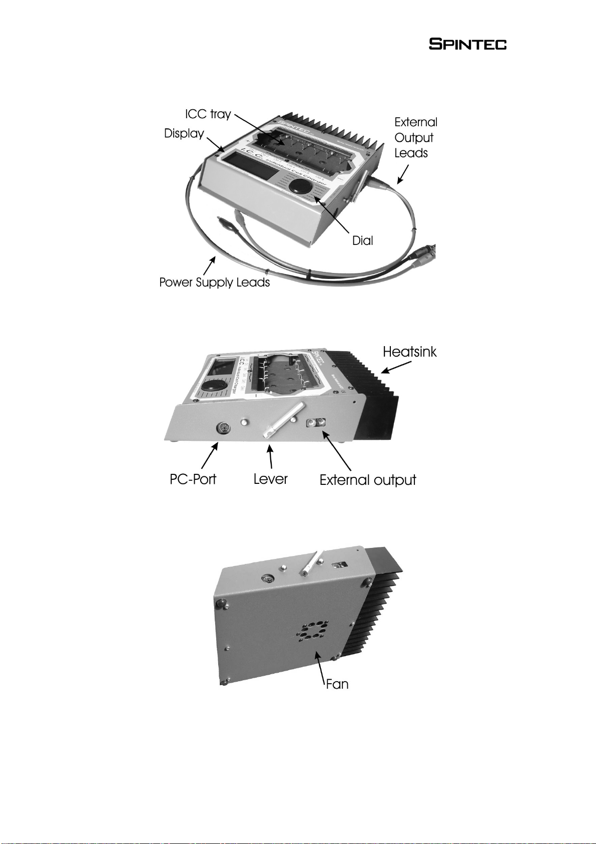
3. Components

5
4. Setting up the unit
4.1 Placement of the unit
Always place the unit on a solid and stable surface. Do not place it
on soft surfaces, like a towel. The fan at the bottom of the ICC
should be able to get fresh air to the unit.
Make sure there is no dirt or metal parts inside the ICC tray.
4.2 Connecting to the power supply
The ICC is designed to work from a power supply delivering
between 12 and 14 volts DC. Connecting to a higher or lower
voltage may cause malfunction or even damage to the unit.
The power supply should be capable of delivering at least the
current that you like to charge at. So for instance, if you like to
charge at 5 amps, a 5 amp supply would be necessary. We advise to
use a supply of minimum 10 amps to use all functionality of the
ICC.
Before you connect the ICC make sure that the power supply is
switched off, no pack is in the tray and nothing is connected on
the external output! Plug in the fixed power supply leads of the
ICC to the supply. Take special notice of the polarity: positive (+)
terminal is red, negative (-) terminal is black. Then switch on the
power supply. If all is fine the ICC will beep once and give you a
welcome message.
When powering down the ICC, first remove the pack from the tray
and disconnect everything from the external output port. Then
switch off the power supply.
4.3 Inserting a pack in the ICC tray
Step 1. Check your pack.
For good charging and discharging without contact errors and
reliable temperature measurements, it is crucial that your pack is
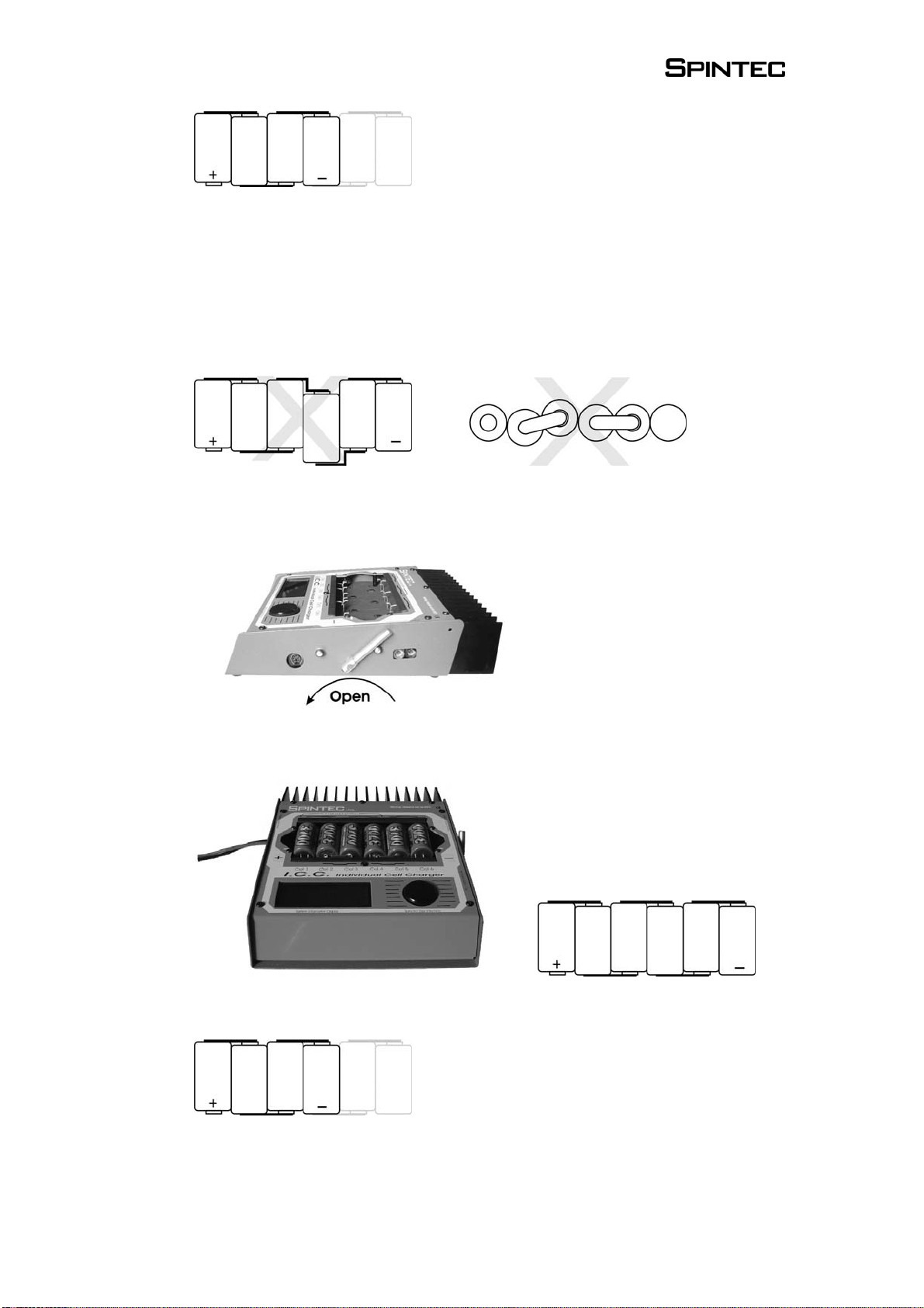
assembled and soldered correctly and nicely aligned.
Your pack should look like this.
6
Or for 4-cell packs, just leave away the right 2 cells.
You can use a flexible wire for connection for ‘saddle pack’ layout,
but make sure the wire is positioned so that you can place the pack
as in the picture.
Make sure all cells are aligned nicely!!
Wrong
Step 2. Open the ICC tray with the lever.
Step 3. Insert the pack.
Watch carefully for polarity. The pack should be placed like this.
Four cell packs should be placed as far as possible to the left in the
tray.

7
Step 4. Close the tray with the lever.
Make sure to hold the lever and slowly close it.
Step 5. Check all connections.
It is important that all probes are in a good position on the pack.
Right
Wrong
Pay extra attention if you are using the ‘Corally style’ bushing
connectors at the end of your pack. The two probes at each end of
the pack should be placed nicely to the side of the bushing. Make
sure that especially on the positive terminal the probes do not slip
of the cell.
Often you can improve contact by moving the pack up and down a
little after closing the lever. This will set the probes for a better
contact.
Move pack slightly up and down to settle the probes.

8
4.4 Connecting a pack to the external output
You can charge packs with 4 to 8 cells on the external output of the
ICC. Use the supplied crocodile-clip leads to connect the pack to
the ICC. Take special care of the polarity: positive (+) terminal is
red, negative (-) terminal is black!
4.5 Connecting a motor to the external output
You can use the external output port of the ICC for powering DC
devices, like running in motors or powering a commutator lathe.
Use the supplied crocodile-clip leads to connect the motor to the
ICC. Take special care of the polarity: positive (+) terminal is red,
negative (-) terminal is black! Make sure you do not let the
positive and negative crocodile clips touch each other.
5. Menu structure navigation using the Spinclick dial
The ICC uses the Spinclick dial to navigate through the menu
structure. By simply turning the dial you move the arrow through
the menu options. Pushing on the dial (clicking) will select the
option at which the arrow is pointing. The next chapter will go
through the menu structure, explaining each function.
Since the firmware of the ICC can be updated, please make sure
that you have the manual that matches the firmware version. For
latest versions please check www.spintec.nl.
5.1 Start up
This is the first menu you will see when you turn on the ICC. It
indicates that all systems are fine and you are ready to go! Simply
click the dial to continue.
W e l c o m e t o S p i nt e c !
→St a r t

9
5.2 Main menu
From here you can access all the functions of the ICC. Charge (1)
and discharge (2) are for the internal ICC tray. External Output (3)
leads you to external charging and motor run.
You can exit any charge or discharge function without stopping the
process. This means you can have two packs charging at the same
time, or discharge a pack in the ICC tray while running a motor on
the external output. The main menu will tell you the status of each
function.
5.2.1. ICC charging
1. Start Charging
Choose Charge (1) in the main menu and then choose Start
Charging (1) in the charge menu to quickly start the charge process
if you know that all settings are fine. To adjust charging parameters
choose Settings (2).
While charging you will see the following information:
oProfile selected (here GP3700)
oTotal charge time (here 12m34s)
oCharge current (here 5.0A), click to change setting
oDelta-peak sensitivity (here 3.5mV), click to change
setting
oTemperature cut-off point (48.5oC), click to change setting
→1 . C h a r g e
2 . D i s c h a r g e
3 . E x t e r n a l O u t p u t
4 . S y s t e m s e t t i n g s
→1 . S t a r t C h a r g i n g
2 . S e t t i n g s
3 . E x i t
C h a r g i n g G P 3 7 0 0
T i m e : 1 2 m 3 4 s
→5 . 0 A 3 . 5 m V 4 8 . 5 ° C
S e t u p E x i t - - >
10
The arrow in the right lower corner indicates that there are more
menu screens with information. Scroll to the right to see them.
You will see respectively:
oStatus of each cell
oVoltage of each cell
oTemperature of each cell
oCapacity of each cell
2. Settings.
You can adjust settings via the ‘Settings’ menu (2) in the charging
menu. Here you can change all charging parameters. The system
will remember your settings made in the ‘Settings’ menu. So if for
example you change the temperature settings of profile ‘GP3700’ it
will remain in memory also if power is disconnected. However, the
settings made in the charge menu screen as above (5.2.1. 1. Start
charging), is temporarily for that charge only.
C 1 : C h a r g e C 4 : C h a r g e
C 2 : F u l l C 5 : C h a r g e
C 3 : C h a r g e C 6 : F u l l
< - - - - >
C 1 : 1 . 2 3 V C 4 : 1 . 2 2 V
C 2 : 1 . 2 2 V C 5 : 1 . 2 3 V
C 3 : 1 . 2 4 V C 6 : 1 . 2 2 V
< - - P a c k : 7 . 3 6 V - - >
C 1 : 1 9 . 3 ° C C 4 : 1 9 . 2 ° C
C 2 : 1 9 . 2 ° C C 5 : 1 9 . 2 ° C
C 3 : 1 9 . 4 ° C C 6 : 1 9 . 3 ° C
< - - P a c k : 1 9 . 2 ° C - - >
C 1 : 1 2 3 4 C 4 : 1 2 3 4 m A h
C 2 : 1 2 3 0 C 5 : 1 2 3 4 m A h
C 3 : 1 2 3 4 C 6 : 1 2 2 8 m A h
< - - P a c k : 1 2 3 4 m A h

11
You can change the following charging parameters:
¾Setup
Choose a profile, each profile contains the full set of
charging parameters. Six profiles are pre-programmed.
¾Deltapeak
The value used for delta peak charge cut-off, measured in
millivolts (mV). The value is set for 1 cell.
¾Temppeak
The maximum temperature a cell is allowed to reach. When
the cell gets to the temperature specified, charging for that
cell is terminated. This can both be used as a charge setting
and safety precaution.
¾Stepcharge
If you select ‘Yes’ then you can specify 3 steps of charging.
This is for experienced users and should be used carefully.
You can set 3 currents: ‘Step 1 cur’, ‘Step 2 cur’ and ‘Step 3
cur’. To specify when charging should proceed from step 1
to step 2, and from step 2 to step 3 you can enter the
milliamphour (mAh) capacity values: ‘Step 1 cap’ and ‘Step
2 cap’. Step 3 will be finished according to the usual
deltapeak and temppeak setting.
¾Min. temp
This is a very useful setting to prevent false peaks. False
peak means that the charger accidentally terminates
charging, while the cell is not yet fully charged. This can
happen with cold cells, or cells that are old or have not been
used for a while. For example, set ‘Min temp’ to 30 °C so
that when a cell is below that temperature charging will
never be ended. This makes sure you always have a fully
charged pack.
¾Lockout
Sometimes cold cells will drop in voltage the first few
minutes of a charge. To prevent false peaks, you can specify
a ‘lockout’ time in which the charger will not stop charging.

12
¾Starttimer
Here you can set a timer so that charging starts at a later
time. This can be useful if you have a race coming up in say
3 hours and you want your pack to be full just in time.
Suppose the charging time is 1 hour, then set the timer at 2
hours. Start the charging, you will see a countdown timer
appear in the charging menu screen.
¾4/6 cell
Choose whether you are charging a 4 or 6 cell pack.
¾Current
This indicates the charge current. You can set the charge
current between 0.1 and 10 Amps. Remember that your
power supply should be able to deliver this current as well.
3. Exiting
When you exit the charge menu, you can choose if you want to stop
charging or not. If you choose ‘No’ the charge process will
continue, and you can scroll through the other menu’s. If you
choose ‘Yes’ charging will be stopped.
Finished charging.
When the charging is finished, the charging statistics will be
shown:
oMatch quality
Gives an indication how close your pack is matched, based
on the
accepted capacity.
oPeak voltage
oPeak temperature
oAccepted capacity
5.2.2. ICC discharging
The same principle of menu structure of the ICC charging (see
5.2.1) applies here. Please read that chapter to understand
operation.

13
1. Settings
¾Current
This is the discharge current of each cell.
¾Cut off
The cut off voltage per cell.
¾4 or 6 cell pack
2. Finished discharging
You will be presented with the following statistical
information:
oMatch quality (%)
oAverage cell voltage in volts (V)
oCapacity in milliamp-hours (mAh)
oEnergy in kilojoule (kJ)
oInternal resistance in milliohms (mΩ)
5.2.3. External Output
Here you have access to functions of the external output
port.
1. Motor Run
Choose Motor Run (1) to connect DC powered devices,
like your racing motors, for running in or testing. Also you
can connect the motor of a commutator lathe.
Operation is simple, click on Voltage to set the output
voltage. Current draw is displayed in Amps. When you exit
this function, motor run will be stopped for safety purpose.
→1 . M o t o r R u n
2 . C h a r g e
3 . E x i t
→V o l t a g e : 6 . 3 V
C u r r e n t : 1 . 4 A
E x i t

14
2. External charging.
This menu gives you control over the external charging feature. It
will operate like any other conventional charger. You can set the
current (Amps) and the delta-peak value. This delta-peak value is
the value for the complete pack! To calculate the value per cell you
need to divide this number by the number of cells in the pack.
Set the charging parameters and click ‘Start’ to begin charging.
You can exit this function while charging continues.
5.2.4. System Settings
1. PC Interface
Use this function to connect to a PC when you have the Interface
Cable (optional item) installed.
The PC Interface Cable can be used to update the firmware of the
ICC with the latest version. You can download the latest version
from www.spintec.nl. Here you can also download your free copy
of the Firmware Upgrade Tool for PC.
To update the ICC take the following steps:
1. Switch the power supply to the ICC off.
2. Remove all packs and cables from the ICC.
3. Connect the Interface Cable between the ICC data port and a free
serial COM port on your PC.
4. Start up the Firmware Upgrade Tool on your PC.
5. Select the right COM port and press the ‘Connect’ button.
6. Now switch on the power supply of the ICC.
7. Scroll to the PC Interface menu and confirm with ‘yes’.
8. The Upgrade Tool should respond with ‘ICC Connected’.
C h a r g i n g →5 . 0 A
2 5 . 0 m V
7 . 6 5 V 1 2 3 4 m A h 2 4 3 s
S t a r t E x i t
→1 . P C I n t e r f a c e
2 . K e y S o u n d O f f
3 . S y s t e m I n f o
4 . E x i t

15
9. Click on the ‘Upgrade’ button and select the latest firmware file
(file extension .icc).
10. Upgrading process will start, progress is indicated by status bar.
This will take a couple of minutes.
It is very important that the upgrading process is not
disturbed. Do not disconnect the cable, do not switch of the
power supply, do not close the Upgrade Tool and do not shut
down the PC!
Note: If anything goes wrong, memory of the ICC will be cleared
and the unit will not start up anymore. In this case the ICC
autmatically always starts up in upgrade mode. So just repeat above
steps to install new firmware in memory.
2. Key Sound Off
Use this function to switch on and off a beeping sound for each
click of the dial.
3. System Info
This menu gives you information about Hardware and Firmware
version numbers. Furthermore it gives you data regarding power
use of the ICC. You can read out power supply voltage, current and
power. Use this to check status of power supply.
4. Temperature units
Here you can select if you want temperature to be displayed in
degrees Celsius (C) or Fahrenheit (F).
6. Charging recommendations
1. The most important thing when charging is to use the right
settings. The ICC is pre-programmed with default setting that
should work well if you select the right profile. There are so
many different types of cells that you might have to find your
own settings. Always comply with the charging
recommendations of the battery manufacturer and matching
company.
The main thing to watch is the difference between NiCd and
NiMH type of cells. This is very important, as delta-peak
settings of these are very different. For NiCd this should be in
the range of 9 or 10 mV per cell, while NiMH cannot have

16
more than 3 or 4 mV. The higher you set this value, the hotter
your battery will become.
2. A very useful feature to prevent false peaking of cells is the
minimum temperature setting. Use this with values between 30
and 35 °C for reliable charges.
3. Keep the charger clean. Any dirt or dust that enters the ICC
can cause malfunction. Also keep it in a cool place out of
direct sunlight.
4. Battery Maintenance.
To get the most out of your packs, you should treat them well.
As heat is an enemy of cells, try to keep them as cool as
possible during charging and discharging. Never allow them to
get warmer than 50 °C.
5. It is best to discharge your pack as soon as possible after
racing. We recommend the Spintec Battery Manager to keep
your packs in top condition. The 35 amps discharge current
makes sure the pack delivers maximum power, while the
cooling-down periods of the Coolflex process keeps the pack
cool. Once every 5 to 10 cycles you can equalize your cells by
discharging them in the ICC tray to about 0.8 or 0.9 Volts per
cell.
6. The ICC is a precise and sensitive measurement and control
system. When you are charging, the system continuously keeps
an eye on the voltage of each cell. Especially when a cell is
almost full, any disturbance can cause a false peak. Try not to
move the charger in this stage. Also try to avoid running a
motor on the external output, or if you do, only change voltage
to it gradually. Do not suddenly connect or disconnect a motor
when voltage setting is not at zero. Doing this causes large
current changes on which the power supply cannot react
quickly enough.

17
7. Error messages
4/6 cell pack detected
You get this warning if you try to charge a 4 cell pack while
settings are on 6 cell, or vice versa. Changing the setting should
solve this error.
Cell contact error
This means that one of the probes is not properly in contact with
the cell. The number in the message tells you which connection is
bad. Number ‘23’ for instance is a probe on the connection
between cell 2 and 3. So is ‘1+’ the positive terminal of the pack,
and ‘6-‘ the negative terminal.
If you see this message, you have the opportunity to correct the
error. Just move your pack or the probe a little to settle, and the
charging or discharging will continue automatically. If you keep
having this problem, make sure your cells and the probes are clean.
No motor connected
When you try to adjust voltage and there is no motor connected, or
the motor is broken, you will get this error. Connect or check your
motor.
No pack
You try to start charging or discharging, but no pack is found in the
system.
Power error
This means that the voltage from the power supply is out of range
(ie. more than 14 volts or less than 12). Check your power supply
to solve this error.
Temperature error.
This means the temperature reading of one of the cells is out of
range. The number indicates which cell sensor gives an error.
Check the temperature of the cell, if it is very hot then you might
have a broken cell.
Voltage error
This means that the voltage of the pack in the ICC tray is out of
range. It could be one cell is dead (zero volts), or voltage is too
high.

18
8. Warnings
1. The heatsink can become very hot. Never touch it directly with
your hands, especially during discharging.
2. Use the ICC only to charge rechargeable nickel-cadmium
(NiCd) or nickel-metalhydride (NiMH) cells that are suitable
for fast-charging. If you attempt to charge other cell types, it
may cause damage to the cells and/or the charger.
3. Avoid any contact of the ICC charger with water or any other
liquids.
4. Never cover the cooling slots or air intakes on the ICC
charger. Place the ICC charger on stable surfaces. Never place
the ICC charger on carpets or cloths.
5. Never allow objects or dirt to enter in the ICC tray. Metal
objects that enter through the ICC tray can damage the
electronics.
6. Do not operate the ICC charger without supervision and never
keep the ICC charger connected to a power supply or a battery
pack when it is not in use.
7. Only charge packs with 4 or 6 cells in the internal ICC tray,
and only charge packs with 4 to 8 cells on the external output.
8. Always comply with the charging instructions of the cell’s
manufacturer.
9. The charger is designed for a supply voltage of 12 Volts. Do
not use a power supply with an output voltage of more than 14
Volts.
10. Make sure you connect the terminals while respecting the
correct polarities, on both the input and output leads, as well as
on the internal ICC tray. Red indicated positive (+) and black
negative (-).
11. If individual cells in the pack heat up excessively, immediately
stop the charging or discharging process.

19
12. Never leave packs connected in/to the ICC when power
supply is switched off.
13. Never remove a pack that is charging or discharging before
switching this function of in the menu.
14. Never disconnect a motor that is running, always turn back
the voltage to zero before disconnecting.
9. Product warranty
Spintec guarantees the ICC charger to be free from defects in
materials and workmanship for a period of 3 months from original
date of purchase (verified by dated, itemized sales receipt).
Warranty does not cover incorrect installation, components worn
by use or excessive force, exceeding the recommended input
voltage, damage resulting from charging fewer or more than the
recommended number of cells, or from improper connection or
charging of inappropriate or defective battery packs, damage from
dissembling the case, tampering with the internal electronics,
allowing water, moisture, or any foreign materials to enter charger
or get onto the PC board. In no case shall our liability exceed the
product’s original cost or cover the cost of batteries damaged while
charging. We reserve the right to modify the provisions stated in
this warranty without notice. Because Spintec has no control over
connection and use of this product, no liability may be assumed nor
will be accepted for damage resulting from the use of this product.
Every ICC charger is thoroughly tested before leaving our facility,
and is therefore considered operational. By the act of
connecting/operating this product, the user accepts all resulting
liability. Spintec is not responsible for any damage caused to
batteries by the ICC.
Table of contents
Popular Batteries Charger manuals by other brands


XS Power Batteries
XS Power Batteries IntelliCHARGER Li1208 user guide

ABB
ABB Terra 360 CE Operation and installation manual

brennenstuhl
brennenstuhl Professional Series operating instructions

MOB
MOB MO9713 user manual

Fisher-Price
Fisher-Price POWER WHEELS H7455 Product features

ANSMANN
ANSMANN ALCS 2-12/0.4 instruction manual