Expion360 EX-85ASC User manual

EX-85ASC
MPPT Solar Charge Controller
/////////////////////////////////////////////
USER MANUAL
////////////////////////////////////////////////////////////////
MODEL EX-85ASC

/////////////////////////////////////////////
///////////////////////////////////////////////////
Lets Get Started

Description
Your Expion360 Solar Charge Controller utilizes maximum
power point tracking (MPPT) technology to optimize the
energy captured from the sun. Solar charge controllers
are essential to convert the energy from the solar panel(s)
into energy that can be used to charge the batteries in your
chosen energy storage solution. Our MPPT charge control-
ler can increase solar charge utilization in excess of 30%
overpulse width modulation (PWM) charge controllers.
This translates to faster charging times using the same
solar panels and more energy to power your
adventures!
1
SOLAR CHARGE CONTROLLER EX-85ASC

Introduction
charge controller and provide added utility for the users of
our leading-edge products. While our MPPT controllers are
protected from damage due to excess internal
temperature, we highly recommend installation in a well
ventilated cabinet away from other devices that produce
large amounts of heat. If the heatsink is unable to dissi-
output current to your batteries. This is to protect the in-
ternal MPPT circuitry and prolong the lifespan of the unit.
Use the Bluetooth app to connect your devices to the
MPPT charge controller.
Thank you for choosing Expion360!
2
SOLAR CHARGE CONTROLLER EX-85ASC

3
SAFETY
Safety Instructions
1. Please read the manual carefully before using the
charge controller.
2. There are no parts inside the controller that can
be maintained or repaired. The user will void the
warranty if the controller is disassembled.
3. Install the controller indoors to prevent exposure
of components and prevent water from entering the
controller.
4. Please install the controller in a well ventilated area
to prevent the heat sink from being overheated.
5. Protecting the charge controller with a fuse or circuit
breaker is recommended.
6. Disconnect the PV input at the fuse or circuit breaker
near the battery terminal prior to installation or
adjusting any wiring at the controller.
7.
will lead to heat build-up at the terminal connection
points and will damage the charge controller.

4
SOLAR CHARGE CONTROLLER EX-85ASC
4 5 6310
11
12
9
1
2
8
1. LCD screen with controls (remote mounting possible)
2. Bluetooth 4.0 BLE module built-in
3. Battery ( + ) terminal
4. Battery ( - ) terminal
5. Solar panel ( - )
6. Solar panel ( + )
7. RS485 communication interface
8. Button
9. TTL communication port
10. Battery temperature sampling port
11. Battery voltage sampling port
12. Relay output interface
7

5
FEATURES
Product Features
• Maximum power point tracking (MPPT) technology
up to 99.9%.
•
• Charging output has active voltage stabilization in
the case of a sudden open circuit at the battery BMS
controller.
• Thermal protection circuit will throttle performance
when the ambient temperature surrounding the heat
sink is high.
• Voltage compensation for charging line losses.
• Bluetooth connectivity for settings and live
information.
• Parallel compatible with additional charge controllers,
for added current handling with available accessory
cable.

6
SOLAR CHARGE CONTROLLER EX-85ASC
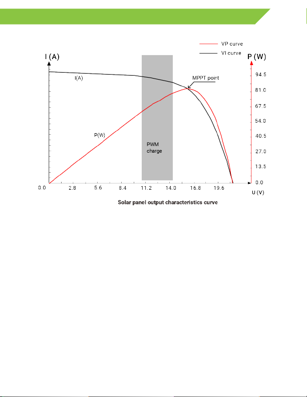
Output Characteristics
The maximum power point for photovoltaics often change
and light conditions. The MPPT controller can rapidly
adjust controller parameters to keep the system at its

7
FEATURES
Lithium Charging Prole
Charging your Expion360 lithium batteries with our MPPT
solar charge controller is the optimal way to deliver
energy. As the voltage of lithium batteries increases
with additional charge from the charge controller, the
MPPT technology is able to adjust the output current to
maximize utilization of the solar power. Once the charge
controller reaches the end of the constant current stage,
the controller will automatically switch to constant voltage

Installation
Step 1: Choose an installation location
Avoid installing the controller in a location with direct
sunlight, high temperature, and water, and ensure good
ventilation around the controller.
Step 2: Mark the mounting position
According to the mounting dimensions of the controller,
drill 4 mounting holes of the appropriate size at the
4 marks. Fix screws into the upper two mounting holes.
8
SOLAR CHARGE CONTROLLER EX-85ASC
WARNING: Danger, explosion hazard!
Never install the controller and a vented
battery in the same enclosed space! Also,
do not install in an enclosed place where
battery gas may collect.
WARNING: Danger, high voltage hazard!
Photovoltaic arrays may generate very high,
open-circuit voltages. Disconnect the circuit
breaker or fuse before wiring and be very
careful during wiring.
CAUTION: When installing the controller,
ensure there is enough air to ow through
the controller’s heatsink, leaving at least
6 inches above and below the controller
for natural convection. If installing the
controller in a closed box, ensure reliable
heat dissipation through the box.
≥ 6 in
≥ 6 in

9
INSTALLATION
Step 3: Fasten the controller
Step 4: Wire for installation safety
WARNING: Danger, electric shock hazard! We strongly
recommend connecting a fuse or circuit breaker to the PV
array and battery terminals to prevent electric shock
hazards during wiring. Make sure the fuse or circuit breaker
is disconnected before wiring.

WARNING: Danger, high voltage hazard! Photovoltaic
arrays may generate very high, open circuit voltages.
Disconnect the circuit breaker or fuse before wiring and be
very careful during wiring.
WARNING: Danger, explosion hazard! If the positive and
negative terminals of the battery, and the wires connected
panel. When wiring the controller, connect the ( + ) positive
Please be very careful during installation.
LED Indicators
10
SOLAR CHARGE CONTROLLER EX-85ASC
① PV Array Status
②Battery State
③ Battery Type
② Battery State Indicator Charge State
Always on MPPT charge
Absorption charge
Float charge
Current limiting charge
Off No charge

11
LED INDICATOR LIGHTS
③ Battery Type Charge State
Red Flooded lead-acid
Yellow Gel lead-acid
Green Sealed lead-acid
Blue 12 V lithium
Purple 24 V lithium
Orange 36 V lithium
Cyan 48 V lithium
White
② Battery State Color Charge State
Green Full battery voltage
Yellow Normal battery voltage
Red, normal on Battery voltage is below the
undervoltage point
Over discharge
Battery overvoltage or
over temperature
*Custom settings should be used by industry professionals only.

12
SOLAR CHARGE CONTROLLER EX-85ASC
Protection Features
Ingress protection
Input power limited protection
If the power of the solar panel is higher than the rated value,
the controller will limit the power of solar panel to prevent
over current damage. Controller enters current-limiting mode.
Battery reverse polarity protection
If the battery polarity is reversed, the system will not
be operational.
PV input overvoltage protection
If the voltage at the PV array input is too high, the controller
will automatically shut off the PV input.
PV input short circuit protection
If the voltage at the PV array input is short-circuited, the
controller will turn off charging. Once the short circuit is
removed, charging will automatically resume.
PV input reverse polarity protection
If the polarity of PV array is reversed, the controller will not
be damaged. Normal operation will continue after wiring is
corrected.
TVS lightning protection
If a lightning strike were to hit the PV array, the controller will
protect the connected circuit from the high voltage spike.
Over-temperature protection
When the temperature of the controller becomes too warm,
the controller will throttle the charging rate or stop charging.

13
PROTECTIONS AND DEVICE CARE
System Maintenance
In order to maintain the best long-term performance of your charge
controller, it is recommended to conduct the following inspections
twice a year.
•
Remove any visible dust from the heat sink with a vacuum or
compressed air.
• Verify that all exposed wires are undamaged due to friction
with nearby objects, dry rot, destruction by insects or rodents,
etc. These are common sources of unexpected damage to
electrical devices. If any damaged wires are found, repair or
replace the wires immediately.
• Check all wiring terminals for corrosion, insulation damage,
signs of high temperature or burning/discoloration. Tighten
terminal screws if there are signs of burning or discoloration
after replacing the wire.
WARNING: Danger, electric shock hazard! Make sure that all power
supplies to the controller have been disconnected before maintenance!

14
SOLAR CHARGE CONTROLLER EX-85ASC
Model MPPT 85 A
System voltage
12 V / 24 V / 36 V / 48 V
Zero load loss (parasitic draw) 0.54 W
Battery voltage 9 V - 64 V
Max PV open circuit voltage 150 V
Max PV input current 70 A
Rated charging current 85 A
Charging current set window 0 A - 85 A
Max PV input (12 V battery bank) 1,100 W
Max PV input (24 V battery bank) 2,200 W
Max PV input (36 V battery bank) 3,300 W
Max PV input (48 V battery bank) 4,400 W
> 99%
Communications Bluetooth, TTL/RS485;
9600 baud, digital bit 3,
stop bit 1, no check bit
Technical Parameters

15
TECHNICAL PARAMETERS
Bluetooth Built-in Bluetooth 4.0 BLE module
Internal temperature
protection
Linear power reduction to protect
controller
Programmable relay DPST 10 A / 250 VAC;
10 A / 30 VDC
Protection function Battery overcharging protection,
battery over discharge protection,
PV input reverse polarity
protection, over temperature
protection of controller, over
current protection of charging,
TVS protection
Operation temperature -30 F up to 150 F
(derate above 100 F)
-34 C up to 65 C
(derate above 37 C )
Elevation
Protection grade IP32
Weight 12.5 lb (5.7 kg)
Product dimensions 12.36 in x 8.95 in x 4.76 in
(314 mm x 227 mm x 121 mm)

16
SOLAR CHARGE CONTROLLER EX-85ASC
Adjust Settings via LCD Screen
Press and hold “ENTER” to access the
“PARAMETER SETTINGS
(1) Press “ENTER” for a short time to adjust the
parameter value
(2) Press “SELECT” for a short time
(3) Press “ENTER” for 2 seconds to save and exit from
the settings mode
(4) Select “LI” battery type for your Expion360 lithium
battery and press “SELECT” to switch between
“system voltage” and “battery type”
(5) For customized battery settings select “USE”, press
“SELECT” to move through the following settings
overdischarge return voltage/ over discharge voltage”

17
LCD MENU

18
SOLAR CHARGE CONTROLLER EX-85ASC
Adjust Settings via Button
There is a button on the controller under the access cover
which is used in conjunction with the battery type indicator
to select the battery type. Generally this method is not used
for adjusting settings. This exists as a backup, in case the
LCD screen becomes damaged in any way.
Press the key for 8 seconds and the battery type indicator
this time). After each press, the battery indicator light turns
another color and changes battery type. After the battery
type is selected, press the button for 8 seconds once or 15
seconds after no operation, the controller will automatically
save the battery type set at present, exit from the setting
mode, and enter into the normal operation mode.
Table of contents
Other Expion360 Batteries Charger manuals