Spirax Sarco CP10 User manual

IM-P403-26 EMM Issue 9 1
1. Safety information
2. General product
information
3. Installation
4. Maintenance
5. Spare parts
© Copyright 2017
Printed in GB
4030150/9
CP10
Sensor
Installation and Maintenance Instructions
IM-P403-26
EMM Issue 9

IM-P403-26 EMM Issue 92
Safe operation of these products can only be guaranteed if they are properly installed,
commissioned, used and maintained by qualified personnel (see Section 1.11) in
compliance with the operating instructions. General installation and safety instructions
for pipeline and plant construction, as well as the proper use of tools and safety
equipment must also be complied with.
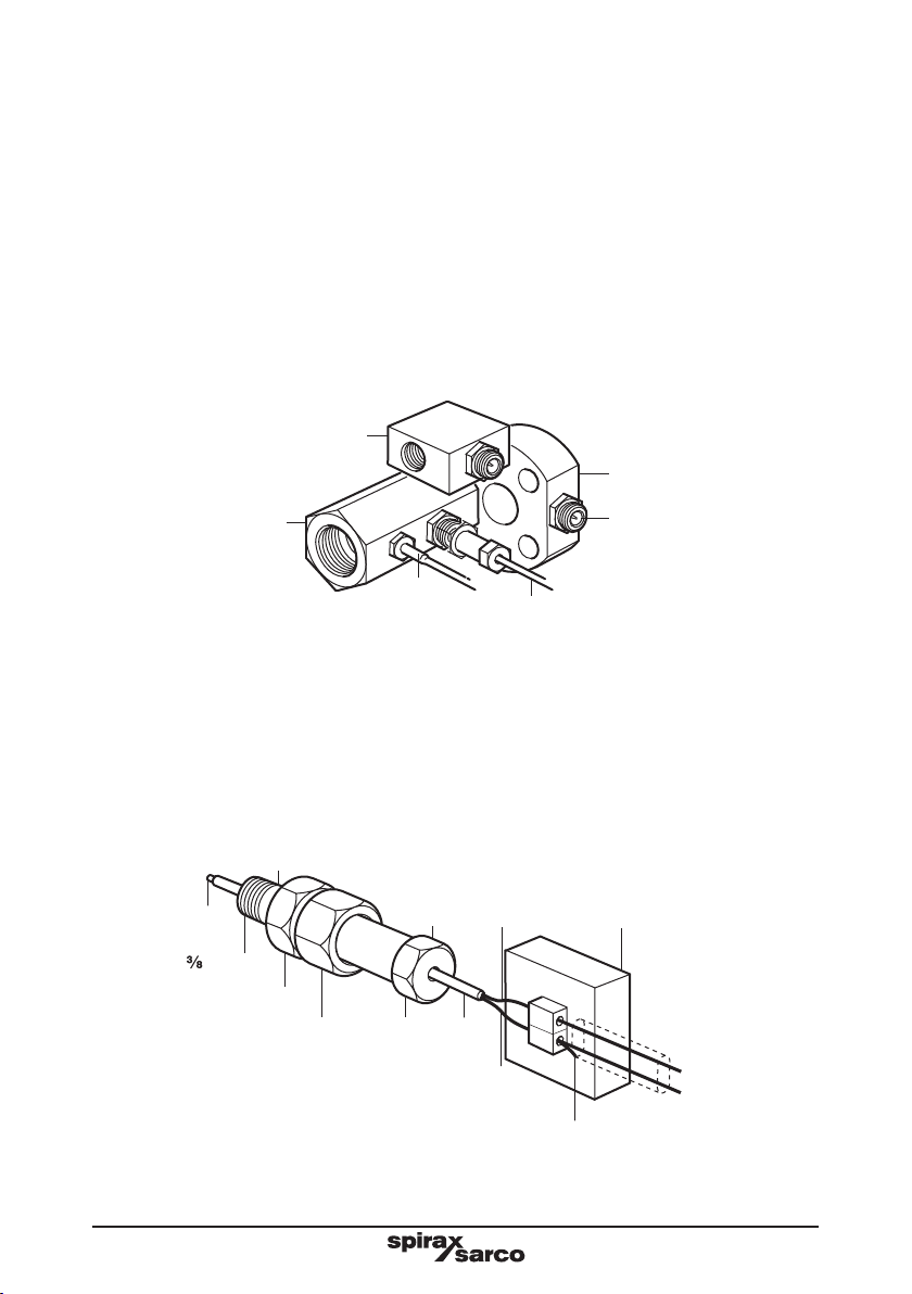
Do not install the probe outdoors without additional weather protection.
Drain / vent holes must be kept clean - do not cover.
1.1 Intended use
Referring to the Installation and Maintenance Instructions, name-plate and Technical
Information Sheet, check that the product is suitable for the intended use /application.
The products comply with the requirements of the European Pressure Equipment
Directive 2014/68/EU and fall within category 'SEP'. It should be noted that products
within this category are required by the directive not to carry the mark.
i) The products have been specifically designed for use on steam and water,
which are in Group 2 of the above mentioned Pressure Equipment Directive.
The products’ use on other fluids may be possible but, if this is contemplated,
Spirax Sarco should be contacted to confirm the suitability of the product for
the application being considered.
ii) Check material suitability, pressure and temperature and their maximum and
minimum values. If the maximum operating limits of the product are lower than
those of the system in which it is being fitted, or if malfunction of the product
could result in a dangerous overpressure or overtemperature occurrence, ensure
a safety device is included in the system to prevent such over-limit situations.
iii) Determine the correct installation situation and direction of fluid flow.
iv) Spirax Sarco products are not intended to withstand external stresses that may
be induced by any system to which they are fitted. It is the responsibility of the
installer to consider these stresses and take adequate precautions to minimise
them.
v) Remove protection covers from all connections and protective film from all
name-plates, where appropriate, before installation on steam or other high
temperature applications.
1.2 Access
Ensure safe access and if necessary a safe working platform (suitably guarded)
before attempting to work on the product. Arrange suitable lifting gear if required.
1.3 Lighting
Ensure adequate lighting, particularly where detailed or intricate work is required.
1. Safety information

IM-P403-26 EMM Issue 9 3
1.4 Hazardous liquids or gases in the pipeline
Consider what is in the pipeline or what may have been in the pipeline at some
previous time. Consider: flammable materials, substances hazardous to health,
extremes of temperature.
1.5 Hazardous environment around the product
Consider: explosion risk areas, lack of oxygen (e.g. tanks, pits), dangerous gases,
extremes of temperature, hot surfaces, fire hazard (e.g. during welding), excessive
noise, moving machinery.
1.6 The system
Consider the effect on the complete system of the work proposed. Will any proposed
action (e.g. closing isolation valves, electrical isolation) put any other part of the
system or any personnel at risk?
Dangers might include isolation of vents or protective devices or the rendering
ineffective of controls or alarms. Ensure isolation valves are turned on and off in a
gradual way to avoid system shocks.
1.7 Pressure systems
Ensure that any pressure is isolated and safely vented to atmospheric pressure.
Consider double isolation (double block and bleed) and the locking or labelling of
closed valves. Do not assume that the system has depressurised even when the
pressure gauge indicates zero.
1.8 Temperature
Allow time for temperature to normalise after isolation to avoid danger of burns.
If parts made from the PTFE have been subjected to a temperature approaching
260 °C (500 °F) or higher, they will give off toxic fumes, which if inhaled are likely
to cause temporary discomfort. It is essential for a no smoking rule to be enforced
in all areas where PTFE is stored, handled, or processed as persons inhaling
the fumes from burning tobacco contaminated with PTFE particles can develop
'polymer fume fever'.
1.9 Tools and consumables
Before starting work ensure that you have suitable tools and / or consumables
available. Use only genuine Spirax Sarco replacement parts.
1.10 Protective clothing
Consider whether you and / or others in the vicinity require any protective clothing
to protect against the hazards of, for example, chemicals, high / low temperature,
radiation, noise, falling objects, and dangers to eyes and face.

IM-P403-26 EMM Issue 94
1.11 Permits to work
All work must be carried out or be supervised by a suitably competent person.
Installation and operating personnel should be trained in the correct use of the
product according to the Installation and Maintenance Instructions.
Where a formal 'permit to work' system is in force it must be complied with. Where
there is no such system, it is recommended that a responsible person should know
what work is going on and, where necessary, arrange to have an assistant whose
primary responsibility is safety.
Post 'warning notices' if necessary.
1.12 Handling
Manual handling of large and / or heavy products may present a risk of injury. Lifting,
pushing, pulling, carrying or supporting a load by bodily force can cause injury
particularly to the back. You are advised to assess the risks taking into account the
task, the individual, the load and the working environment and use the appropriate
handling method depending on the circumstances of the work being done.
1.13 Residual hazards
In normal use the external surface of the product may be very hot. If used at the
maximum permitted operating conditions the surface temperature of some products
may reach temperatures of 239 °C (462 °F).
Many products are not self-draining. Take due care when dismantling or removing
the product from an installation (refer to 'Maintenance instructions').
1.14 Freezing
Provision must be made to protect products which are not self-draining against
frost damage in environments where they may be exposed to temperatures below
freezing point.
1.15 Disposal
Unless otherwise stated in the Installation and Maintenance Instructions, this product
is recyclable and no ecological hazard is anticipated with its disposal providing due
care is taken, except:
PTFE:
-Can only be disposed of by approved methods, not incineration.
-Keep PTFE waste in a separate container do not mix it with other rubbish, and
consign it to a landfill site.
1.16 Returning products
Customers and stockists are reminded that under EC Health, Safety and Environment
Law, when returning products to Spirax Sarco they must provide information on any
hazards and the precautions to be taken due to contamination residues or mechanical
damage which may present a health, safety or environmental risk. This information
must be provided in writing including Health and Safety data sheets relating to any
substances identified as hazardous or potentially hazardous.

IM-P403-26 EMM Issue 9 5
2. General product information
Fig. 1 CP10 sensor
2.1 General product description
The CP10 sensor is a conductivity probe specified for use in total dissolved solids (TDS) and
conductivity control systems.
It is a sealed unit consisting of a central stainless steel sensor tip, PEEK insulator, PTFE
sealing ring, stainless steel body, disc springs and washer.
There are two threads on the CP10 sensor:
-The electrical end connection is threaded M22 to accept the PT2 plug tail.
-The probe-tip end is threaded G3/8 to suit the appropriate sensor chamber.
The unit is supplied with an S-type stainless steel gasket.
Electrical connection is via an IP65 connector (supplied separately).
The CP10 sensor and PT2 plug tail are intended for use with a low voltage limited power
source. These are approved by Underwriters Laboratory as Listed accessories for use with
Spirax Sarco controllers.
2.2 Pressure / temperature limits
Body design PN40
Maximum pressure /temperature 32 bar g at 239 °C (464 psi g at 462 °F)
Designed for a maximum cold hydraulic test
pressure of: 60 bar g (870 psi g)
Minimum conductivity generally10 S / cm or 10 ppm, but see controller IMI.

IM-P403-26 EMM Issue 96
Caution: Do not install the sensor outdoors without additional weather protection.
Fit the sensor chamber in a vertical or horizontal pipeline with suitable isolation valves to
allow inspection / cleaning of the sensors. Reducers may be fitted if required. Flow can be in
either direction. The sensors themselves must be horizontal.
The TP20 has a taper thread, and may be installed using PTFE sealing tape if required.
The CP10 sensor is provided with an S-type stainless steel gasket for sealing. PTFE tape
may be used on the CP10 threads, but check that the resistance to earth is less than 1 after
installation.
Fit the sensors to the chamber and tighten to a torque of 60 N m (44 lbf ft).
Fit PT2 plug tail (or other Spirax Sarco plug tail) to the CP10 sensor and tighten.
Caution: Ensure the PT2 wire is not exposed to a temperature greater than 120 °C (248 °F).
3.1 Electrical installation
Cabling should be installed in accordance with BS 6739 - Instrumentation in Process Control
Systems: Installation design and practice or local equivalent.
CP10
sensor
PT2
plugtail Red wire to
sensor pin
To
blowdown
controller
Screen
Junction box
(for connection to conduit)
Blue wire earthed
via PT2 and CP10
Nut
25 mm A/F
24 mm A/F
Sensor pin
Insulation
" BSP
Connect screen to earth (blue wire)
Fig. 3 Wiring diagram
3. Installation
S11 sensor chamber
CP10
PT2 (or PT3) plug tail
TP20
Temperature sensor
S10
sensor chamber
CP10 sensor
S20
sensor chamber
Ensure resistance from probe body to
pipework / boiler shell is less than 1 .
Fig. 2 Typical applications:
sensor

IM-P403-26 EMM Issue 9 7
4. Maintenance
We recommend that the CP10 is removed for cleaning and inspection at least once a year,
though the frequency of maintenance will depend on the quality and flowrate of the boiler
water or condensate.
-Isolate and depressurise the system, (or with the system empty), remove the CP10 sensor.
-Inspect male and female threads for signs of damage, which may have occurred through
overtightening, leading to torn threads or even localised cold welding (galling / picking
up). If damage has occurred replace the CP10 sensor.
-If after inspection there is no damage to the thread proceed to clean the sensor tip with
fine wet-or-dry paper, and the insulator with a cloth or bristle (not wire) brush.
-Inspect the insulator and sensor tip for erosion, damage, or pitting, and refit or replace
as necessary.
-Retighten the CP10 sensor to a torque of 60 N m (44 lbf ft). Note: Always fit a new gasket.
5. Spare parts
The spare parts available are detailed below. No other parts are supplied as spares.
Available spares
Gasket Stock No. 0957191 Pack of 10
How to order spares
Always order spares by using the description given in the column headed 'Available spares'
and state which product they are for.
Example: 1 off Gasket (pack of 10) for a Spirax Sarco CP10 sensor - Stock number 0957191.

IM-P403-26 EMM Issue 98
Table of contents
Other Spirax Sarco Accessories manuals

Spirax Sarco
Spirax Sarco LC2300 User manual

Spirax Sarco
Spirax Sarco LP20 User manual

Spirax Sarco
Spirax Sarco WLS1 User manual

Spirax Sarco
Spirax Sarco LT2010 User manual

Spirax Sarco
Spirax Sarco LP30 User manual

Spirax Sarco
Spirax Sarco ITD32 User manual

Spirax Sarco
Spirax Sarco SSC20 User manual

Spirax Sarco
Spirax Sarco SSC20 User manual