Spirax Sarco LT2010 User manual

IM-P402-62 AB Issue 5 1
LT2010
Level Transmitter
Installation and Maintenance Instructions
IM-P402-62
AB Issue 5
4025351/5
1. General
safety information
2. General
product information
3. Installation
4. Setting up the transmitter
5. Wiring diagrams
6. Commissioning
. Maintenance
8. Fault finding
LT2010
>100%
>0%
Printed in the UK © Copyright 2003

IM-P402-62 AB Issue 52
1. General safety information
Fig. 1
LT2010
>100%
>0%
Power on
Span
Span adjust
Zero adjust
Zero
Clamping screw
Clamping screw
Your attention is drawn to Safety Information Leaflet IM-GCM-10 as well as to any
National or local regulations.
Safe operation of the product depends on it being properly installed, commissioned
and maintained by a qualified person in compliance with the operating instructions.
It is essential to comply with general installation and safety instructions for pipeline
and plant construction, as well as to make proper use of tools and safety equipment.
The product is designed and constructed to withstand the forces encountered
during normal use. Use of the product for any other purpose, or failure to install the
product in accordance with these Installation and Maintenance Instructions, could cause
damage to the product, will invalidate the marking, and may cause injury or fatality
to personnel.
Warning
Isolate the mains supply before unplugging the transmitter since hazardous voltages will
be exposed on the transmitter base. This product complies with the requirements
of Electromagnetic Compatibility Directive 89/336/EEC by meeting the standards of:
-BS EN 50081-1 (Emissions) and
-BS EN 61000-6-2 (Immunity).
The following conditions should be avoided as they may create interference above
the limits specified in BS EN 61000-6-2 if:
-The product or its wiring is located near a radio transmitter.
-Excessive electrical noise occurs on the mains supply. Power line protectors (ac)
should be installed if mains supply noise is likely. Protectors can combine filtering,
suppression, surge and spike arrestors.
-Cellular telephones and mobile radios may cause interference if used within
approximately 1 metre (39") of the product or its wiring. The actual separation distance
necessary will vary according to the surroundings of the installation and the power
of the transmitter.
If this product is not used in the manner specified by this IMI, then the protection
provided may be impaired.

IM-P402-62 AB Issue 5 3
2. General product information
The LT2010 is a level transmitter which converts the voltage output from a Spirax Sarco
capacitance probe into an isolated 0 - 20 or 4 - 20 mA signal proportional to water level. The
outputcanbescaledtorepresentanydesiredwaterlevelrange,thegaugeglassforexample.Two
or more transmitters may be used with a single capacitance probe if required.
The LT2010 can also power and be used with any 2 wire 0 - 20 or 4 - 20 mA transmitter, for example
for pressure, temperature, or level transmission using a pressure or differential pressure transmitter.
An inverse output can be selected for level monitoring with a differential pressure transmitter. The
transmitterhasLEDindicationofmainson,zeropoint,andspansettings,andawavefilterfunction
which gives an averaged output, maintaining a stable signal under the very different turbulence
conditions found in tanks and high output boilers.
The LT2010 is set up before installation to suit the mains supply voltage and to provide the
required functions, using internal switches. See 'Setting up the transmitter', Section 4. Calibration
can be altered without removing or dismantling the unit, using the zero point and full scale/span
potentiometers on the front panel.
Maximum ambient temperature 55°C (131°F)
Minimum ambient temperature 0°C (32°F)
Pollution degree 2
Overvoltage category I I
Indoor use only
Altitude 2 000 m (6 561 ft)
Humidity Maximum relative humidity 80% for temperature up to 31°C (87.8°F)
decreasing linearly to 50% relative humidity at 40°C (104°F).
Protection rating IP40
Mains supply voltage 230 V setting 198 V - 264 V
115 V setting 99 V - 132 V
Frequency 50 - 60 Hz
20mmCartridge,100mAanti-surge(T).FortheULversion,replacement
Fuse type fuses must be UL recognised to maintain the integrity of the approval.
Maximum power consumption 6 VA
Maximum cable length (transmitter to probe) 100 m (328 ft)
Terminal torque rating 1 N m (9 lbf ft)

IM-P402-62 AB Issue 54
4. Setting up the transmitter
4.1 Setting up the transmitter
The transmitter is set up as follows:
-230 V mains supply.
-Wave filter off.
-4-20 mA.
-Normal (non-inverse) output.
-Capacitance probe input (voltage).
4.2 To change the mains supply voltage:
-Unplug the transmitter from its base.
-Remove the rear cover panel.
-Slide out the printed circuit board.
-Slide the voltage selector switch to the 115 V setting.
-Replace the printed circuit board.
-Ensure that the LED’s engage with the holes in the front panel.
-Replace the rear cover panel.
Slide switch
up for 115 V
setting
230 Transformer
Fig. 2
3. Installation
WARNING:
Isolate the mains supply before unplugging the transmitter since hazardous voltages will be
exposed on the transmitter base.
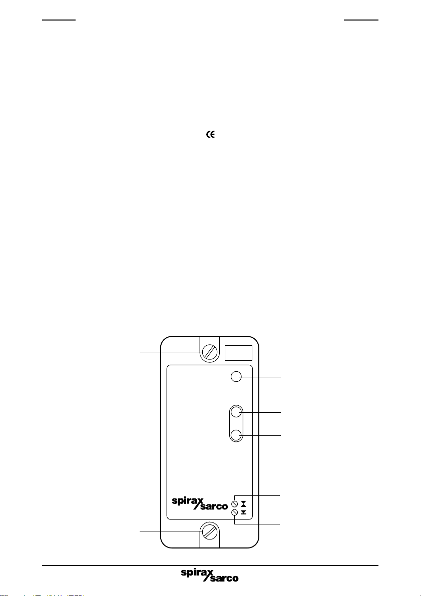
To unplug the transmitter from its base, undo the two retaining screws and pull the transmitter
straight forwards. Rocking the transmitter in the vertical plane will ease removal.
The transmitter must be installed in an enclosure or control panel to provide environmental
protection (Pollution Degree 2). Spirax Sarco can provide suitable metal or plastic enclosures.
The transmitter may be mounted on a 'top hat' DIN rail using the clip provided or the clip can be
removed and the transmitter base screwed directly to a chassis plate.
Caution: Allow 15 mm spacing between multiple units for air circulation.
The transmitter is for installation Category II (Overvoltage category) and must be installed in
accordance with IEC 60364 or equivalent. The transmitter and all connected circuits must
have a common isolation system which meets the relevant requirements of IEC 60947-1 and
IEC 60947-3 or equivalent. This must be positioned close to the transmitter and clearly identified
as the disconnect device.
A quick blow 3 amp external fuse must be fitted in all phases of the transmitter supply.
For the US and Canadian markets the transmitter must be wired in accordance with the National
and Local Electrical Code (NEC) or Canadian Electrical Code (CEC).
Screened high temperature, 3 core, 1 mm²(18 - 16 AWG) copper cable is required for the probe
wiring.Themaximumpermittedlengthis100metres(328ft).Usecablewithasuitabletemperature
rating for the installation. Pirelli FP200 or Delta Crompton Firetuf OHLS are suitable cables for the
standard version. Use NEC Class 1 wiring for the UL version.
Cabling should be installed in accordance with BS 6739 - Instrumentation in Process Control
Systems: Installation design and practice or local equivalent.
Connect the screens as shown in the wiring diagrams (Section 5).
If the product is not used in the manner specified by this IMI, then the protection provided
may be impaired.
20 mm fuse
100 mA anti-surge (T)

IM-P402-62 AB Issue 5 5
4.3 To change the function settings
-Unplug the transmitter from its base.
-Remove the rear cover panel.
-Slide out the printed circuit board.
-An 8-way switch on the printed circuit board determines the transmitter functions.
-Set the switches to the positions shown in the diagram for the chosen functions.
-Replace the printed circuit board.
-Ensure that the LED’s engage with the holes in the front panel.
-Replace the rear cover panel.
Note that Switches 4, 5 and 7 are not used.
4.4 Current/voltage input - Switches 1 and 2
The transmitter is supplied set for use with a capacitance probe, (voltage input).
If a current input is required, for use with a temperature transmitter for example, set switch 1 and
2 to ON.
4.5 Inverse output - Switch 3
The transmitter is supplied set so that a rising level at the probe will give a rising output from the
transmitter.
If a falling transmitter output is required with a rising input, as when using a differential pressure
transmitter for level monitoring, set Switch 3 to OFF.
4.6. Wave filter - Switch 8
Thisfeature averages the signal overa longer periodfor highoutput boilers wherewaves andhigh
turbulence may otherwise cause continuous oscillation of the output signal.
If the wave filter is required, set Switch 8 to ON.
Fig. 3
Capacitance probe
input (voltage)
Capacitance probe
input (voltage)
Inverse output
Not used
Not used
4 - 20 mA
Not used
Filter OFF
Current input ( 4 - 20 mA)
(or 0 - 2 V)
Normal output
0 - 20 mA
Filter ON
ON
1 2 3 4 5 6 7 8

IM-P402-62 AB Issue 56
1
2
3
10
11
12
Termination
box Screen
Brown
Red
Orange
Black *
*See PA20 Installation and Maintenance Instructions
for sensitivity selection
LT2010
Transmitter
+
IN
Common
Flying leads supplied
with PA20
(approximately 300 mm [12"])
Wiring diagram UL version
PA20 preamplifier and LP20 capacitance probe
(see PA20 and LP20 Installation and Maintenance Instructions)
Screen connection
An earth current loop is created if a wire or screen is connected between two earth points, which
areatdifferentpotential(voltage).Iftheinstructionsarefollowedcorrectly,thenthepreamplifierand
transmitter screen will only be connected to earth at one end.
Note: The PA20 earth terminal is a functional earth rather than a protective earth.
A protective earth provides protection from electric shock under a single fault condition. This
product has double insulation and therefore does not require a protective earth.
A functional earth is used in order for the product to operate. In this application, the earth
(tank/boiler shell) is used as the common of the probe/preamplifier. It also provides a sink/drain
for any electrical interference.
Ensure that the screen is connected to the earth terminal of the PA20 and to the common terminal
of the transmitter.
Ensure the common terminal of the transmitter is not internally earthed. (All Spirax Sarco boiler
controls are internally isolated from earth).
The common terminal of the transmitter must only be earthed via the PA20.
CAUTION:
Do not connect the common terminal to an earth local to the transmitter. To do so may
induce an earth current loop, which may reduce the performance or damage the product.
5. Wiring diagrams
Fig. 4
See CAUTION above
Ensure resistance from probe body to
pipework/boiler shell is less than 1 W.

IM-P402-62 AB Issue 5 7
1
2
3
4
5
6
7
8
9
10
11
12
+
+
11
12
10
11
12
10
11
12
+
10
11
12
10
11
12
ON
12
ON
12
ON
12
ON
12
A
1
2
3
1
2
3
Select
voltage
internally
4 - 20 mA Test - connect ammeter between
terminals 5 and 6. Do not dissconnect loop.
0 - 20 mA
or
4 - 20 mA
LP20/PA20
Capacitance
probe
Alternative
remotely
powered
current
or voltage
input
INPUT
L
N
Mains
Fuse
Max. 3A
Common
Common
Additional
unit if fitted
4 - 20 mA transmitter
powered from the
LT2010
Additional
unit
Multiple transmitters
Several transmitters can be
connected to a single probe if
required.
Connect wiring as shown in the
diagram.
Ensure resistance from probe
body to pipework/boiler shell is
less than 1 W.
Links on preamplifier provide sensitivity
selection - see preamplifier IMI
The earth pin is internally connected to the
PA20 body and earthed by the LP20 probe.
Do not connect this earth pin to other earths.
Fig. 5
Test
Output - Maximum 1000 W
LP20/PA20
Capacitance
probe Screen
Screen
Ensure resistance from probe body to
pipework/boiler shell is less than 1 W.See CAUTION page 6

IM-P402-62 AB Issue 58
To commission the transmitter proceed as follows:-
1. Ensure the transmitter is set up for the correct functions and mains supply voltage.
2. Alter the water level in the tank or boiler to the required low level, or zero point. This is
thepoint at which you require the 4 mA, (or 0 mA) to be transmitted.
3. Adjust the zero adjust potentiometer (bottom) until the > 0% LED just lights.
4. Alter the water level to the required high level. This is the level at which the 20 mA signal is
to be transmitted. (Note: that these output signals will be reversed if 'reverse action'
as been selected on switch 3).
5. Adjust the span adjust potentiometer (top) until the > 100% LED just lights.
6. As an aid to commissioning, an ammeter may be connected across the test output pins (5
and 6), to indicate transmitted current.
6. Commissioning
. Maintenance
8. Fault finding
No special servicing or maintenance of the transmitter is necessary. Boiler water level controls
andlevelalarms,however,dorequiretestingandinspection.GeneralguidanceisgiveninHealth
and Safety Executive Guidance Note PM5.
For specific instructions for the Spirax Sarco system please see separate literature.
Available spares
Spare fuses Stock No. 4033380 Set of 3
Most faults which occur on commissioning are due to incorrect wiring or setting up.
In the case of problems the following checklist may be helpful:-
Mains on LED not lit:
-No live supply
-Neutral not connected
-Transmitter internal fuse blown.
Transmitter internal fuse blown:
-Check the mains supply voltage is lower than 264 V, and that the ambient temperature inside
the control panel is less than 55°C (131°F). If either of these limits has been exceeded, it
is possible that the transformer internal thermal fuse has blown, and that the transformer
will need to be replaced.
-Ensure that the probe supply voltage is between 24 Vdc and 35 Vdc between terminals 10 and
12 of the transmitter, or terminals 1 and earth of the probe.
-The probe output voltage should be 1 Vdc to 6 Vdc between terminals 11 and 12 of the
transmitter, or terminals 2 and earth of the probe, depending on the level.
-The voltage increases with the level, even when inverse output has been selected.
Table of contents
Other Spirax Sarco Accessories manuals

Spirax Sarco
Spirax Sarco CP10 User manual

Spirax Sarco
Spirax Sarco ITD32 User manual

Spirax Sarco
Spirax Sarco LC2300 User manual

Spirax Sarco
Spirax Sarco LP20 User manual

Spirax Sarco
Spirax Sarco SSC20 User manual

Spirax Sarco
Spirax Sarco SSC20 User manual

Spirax Sarco
Spirax Sarco WLS1 User manual

Spirax Sarco
Spirax Sarco LP30 User manual