Spirax Sarco LC2300 User manual

IM-P402-72 AB Issue 6 1
LC2300
Level Controller
Installation and Maintenance Instructions
IM-P402-72
AB Issue 6
4025350/6
1. General
safety information
2. General
product information
3. Installation
4. Setting up the
controller
5. Wiring diagrams
6. Commissioning
7. Maintenance
8. Fault finding
LC2300
>50%
>100%
<0%
Printed in the UK © Copyright 2003
Archive

IM-P402-72 AB Issue 6
2
1. General safety information
Your attention is drawn to the Safety Information leaflet, IM-GCM-10, as well as to any
National or local regulations.
Safe operation of the product depends on it being properly installed, commissioned
and maintained by a qualified person in compliance with the operating instructions.
It is essential to comply with general installation and safety instructions for pipeline
and plant construction, as well as to make proper use of tools and safety equipment.
The product is designed and constructed to withstand the forces encountered
during normal use. Use of the product for any other purpose, or failure to install the
productinaccordancewiththeseInstallationandMaintenanceInstructions,couldcause
damage to the product, will invalidate any marking, and may cause injury or fatality
to personnel.
Additional Safety Notes:
Level control and level limiting products in steam boilers
Products/systems must be selected, installed, operated, and tested in accordance with:
-Local or National standards and regulations.
-Guidance Notes, (Health and Safety Executive PM5 in the UK).
-The requirements of Approvals Authorities.
-Boiler Inspection Bodies.
-Boiler manufacturer’s specifications.
Two independent low water limiting systems must be installed on steam boilers.
Level probes must be installed in separate protection tubes/chambers, with
sufficient clearance between the tips, and earth.
Each probe must be connected to an independent controller. The alarm relays
must isolate the boiler heat supply at low alarm status.
A high water alarm may be part of the water level control, or a separate system. An
independenthighwateralarmsystemmustbefittedif itisconsideredasafetyrequirement.
Inthiscase,therelaysmustsimultaneouslyisolatethefeedwatersupplyandtheboilerheat
supply at high alarm status. All boiler water limiters require regular functional testing.
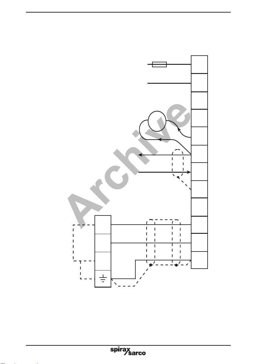
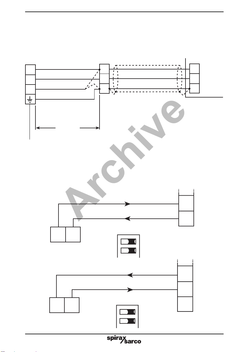
The level probe and controller is only part of the safety system. To complete the
system,additionalcircuitry(wiring,relays,alarmbell/lampetc.)isrequired. Circuitry
must be designed and wired to 'fail-safe'.
Asuitablewatertreatment regimemustbeusedtoensure continuoussafeandcorrect
operation of the control and limiter systems. Consult the above authorities and a
competent water treatment company.
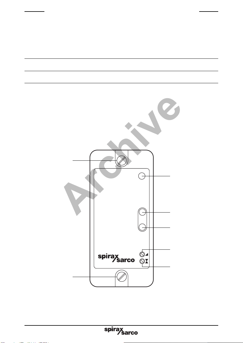
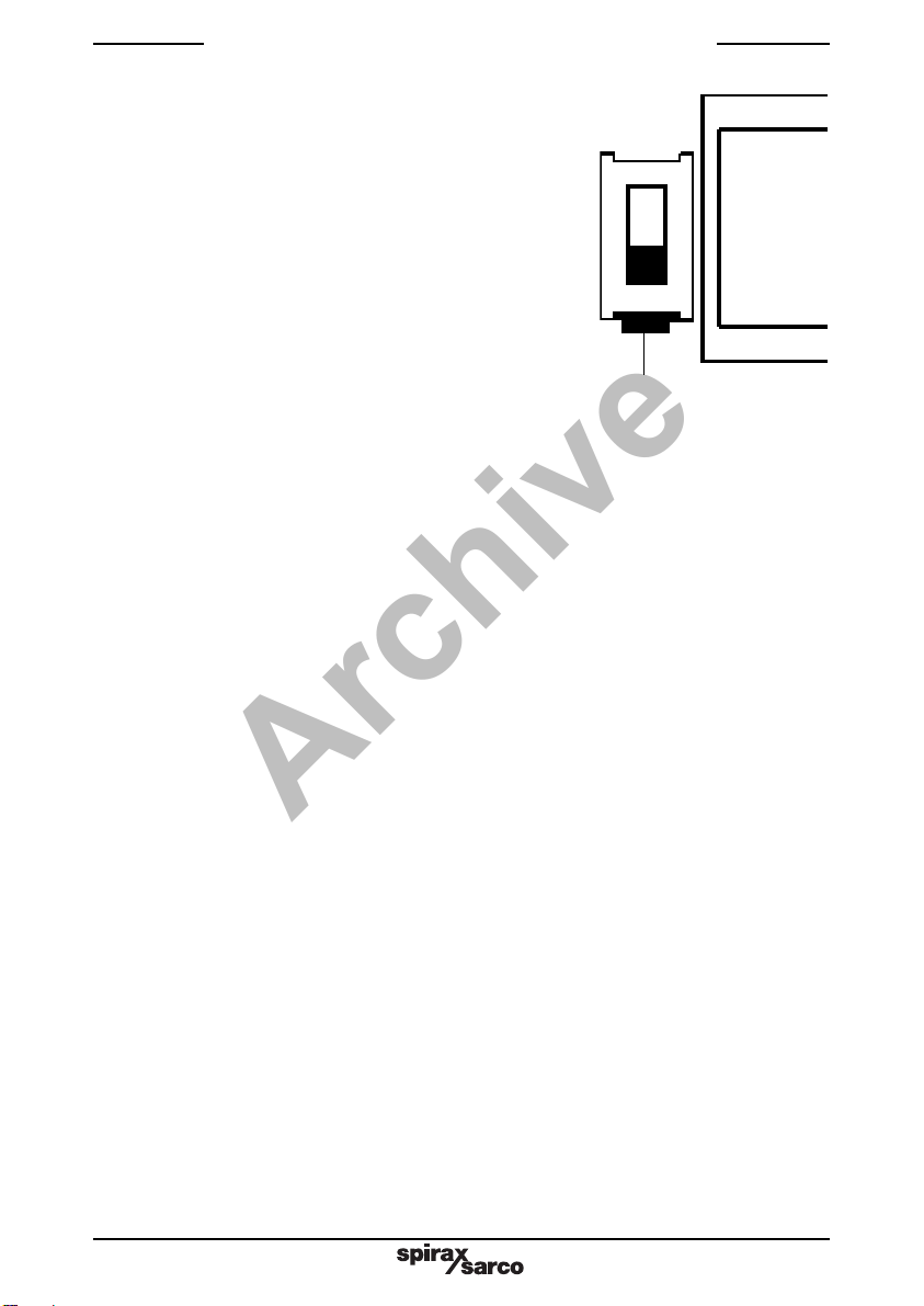
Warning
Isolate the mains supply before unplugging the controller since hazardous voltages will
be exposed on the controller base. This product complies with the requirements
of Electromagnetic Compatibility Directive 89/336/EEC by meeting the standards of:
-Emissions EN 61326: 1997 A1 + A2 Class B equipment Table 4.
-Immunity EN 61326: 1997 A1 + A2 Class A equipment Table 1.
The following conditions should be avoided as they may create interference above
the limits specified in EN 61326 (Immunity) if:
-The product or its wiring is located near a radio transmitter.
-Excessive electrical noise occurs on the mains supply. Power line protectors (ac)
should be installed if mains supply noise is likely. Protectors can combine filtering,
suppression, surge and spike arrestors.
-Cellular telephones and mobile radios may cause interference if used within
approximately 1 metre (39") of the product or its wiring. The actual separation distance
necessary will vary according to the surroundings of the installation and the power
of the transmitter.
If this product is not used in the manner specified by this IMI, then the protection
provided may be impaired.
Archive

IM-P402-72 AB Issue 6 3
2. General product information
The Spirax Sarco LC2300 is used to control the positioner of a pneumatic valve in response to
a signal from a capacitance probe, providing proportional modulating control of liquid levels.
TheLC2300 can alsobe used withanytwo-wire4 -20mA transmitter,forexample forpressure,
temperature, or level control using a pressure or differential pressure transmitter.
Reverse acting or direct output can be selected.
The controller has a mains on LED, and two level indicators:-
The green LED (>50%) Indicates that the output current is greater than 50%,
i.e. above the set point output current.
The amber LED (>100% / < 0%) Indicates that the output is greater than 20 mA
or less than 0 / 4 mA.
A three stage wave filter gives an averaged output, maintaining a stable signal under the very
wide variations in turbulence found in tanks and high output boilers.
The LC2300 is set up before installation to suit the mains supply voltage and to provide the
requiredfunctions,usinginternalswitches.SeeSection4.1,'Settingupthecontroller'.Calibration
canbealteredwithoutremovingordismantlingtheunit,usingthesetpointandproportionalband
potentiometers on the front panel.
Fig. 1
Power on
Green LED
Amber LED
Set point
Proportional band
LC2300
>50%
>100%
<0%
Clamping screw
Clamping screw
Archive

IM-P402-72 AB Issue 6
4
Technical data
Maximum ambient temperature 55°C (131°F)
Minimum ambient temperature 0°C(32°F)
Pollution degree 2
Overvoltage catagory II
Indoor use only
Altitude 2 000 m (6 561.5 ft)
Humidity Maximum relative humidity 80% for temperatures up to 31°C (87.8°F)
decreasing linearly to 50% relative humidity at 40°C (104°F).
Protection rating IP40
Mains supply voltage 230 V setting 198 V - 264 V
115 V setting 99 V - 132 V
Frequency 50 - 60 Hz
Fuse type 20 mmcartridge, 100mAanti-surge (T). Forthe ULversion, replacement
fuses must be UL recognised to maintain the integrity of the approval.
Maximum power consumption 6 VA 0 - 2 V
Input 1 0 - 6 V
Selectable inputs 0 - 20 mA
4 - 20 mA
Input 2 (opposite sense to input 1) 0 - 20 mA
4 - 20 mA
Note: See separate literature for two element control.
0 - 20mA into 1 kΩmaximum
4 - 20mA into 1 kΩmaximum
Output (isolated) or
20 - 0mA into 1 kΩmaximum
20 - 4mA into 1 kΩmaximum
Wave filter - three stages Filter 1 position (Minimum damping) 0.07Hz
Response band width Filter 2 position (Medium damping) 0.02Hz
(designed for slowly varying signals) Filter 3 position (Maximum damping) 0.01Hz
Set point range 0% - 100% of input
Proportional band range 5% - 100% of input
Transducer supply 24 - 37 Vdc 20mA maximum
Maximum cable length (controller to probe) 100 m (328 ft)
Terminal torque rating 1 N m (9 lbf in)
Archive

IM-P402-72 AB Issue 6 5
3. Installation
WARNING
Isolate the mains supply before unplugging the controller since hazardous voltages
will be exposed on the controller base.
The controller must be installed in a suitable industrial control panel or fireproof enclosure to
provide impact and environmental protection (pollution degree 2). Spirax Sarco can provide
suitable plastic or metal enclosures (for the standard controller only).
To unplug the controller from its base, undo the two clamping screws and pull the controller
straight forwards. Rocking the controller in the vertical plane will ease removal.
The controller may be mounted on a 'top hat' DIN rail using the mounting clip provided, or the
clip may be removed and the controller base screwed directly to a chassis plate.
Caution: Allow 15 mm (5
/
8") spacing between multiple units for air circulation.
The controller is for installation category II (Overvoltage category) and must be installed in
accordance with IEC 60364 or equivalent. For the US and Canadian markets the controller
must be wired in accordance with the National and Local Electrical Code (NEC) or Canadian
ElectricalCode(CEC).Thecontrollerandallconnectedcircuitsmusthaveacommonisolation
systemwhichmeetstherelevantrequirementsofIEC60947-1and IEC60947-3orequivalent.
This must be positioned close to the controller and clearly identified as the disconnect device.
A quick blow 3 amp external fuse must be fitted in all phases of the controller supply.
Screened high temperature, 3 core, 1 mm2(18 - 16 AWG) copper cable is required for the
probe wiring. The maximum permitted length is 100 metres (328 ft). Use cable with a suitable
temperature rating for the installation. Pirelli FP200 or Delta Crompton Firetuf OHLS are
suitable cables for the standard version. Use NEC Class 1 wiring for UL version.
Connect the screens as shown in the wiring diagrams (Section 5).
Cabling should be installed in accordance with BS 6739 - Instrumentation in Process Control
Systems: Installation design and practice or local equivalent.
If the product is not used in the manner specified in this IMI, then the protection
provided may be impared.
Archive

IM-P402-72 AB Issue 6
6
4. Setting up the controller
4.1 Setting up the controller
The controller is supplied set up as follows:
-230V mains supply.
-Capacitance probe input (voltage).
-Reducing output with increasing input.
-4 - 20mA output.
-Wave filter position 1 (minimum damping).
4.2 To change the mains supply voltage:
-Unplug the controller from its base.
-Remove the rear cover panel.
-Slide out the printed circuit board.
-Slide the voltage selector switch to the 115 V setting.
-Replace the printed circuit board.
-Ensure that the LEDs engage with the holes in the front panel.
-Replace the rear cover panel.
4.3 To change the function settings:
-Unplug the controller from its base.
-Remove the rear cover panel.
-Slide out the printed circuit board.
-An 8-way switch on the printed circuit board determines the controller functions.
-Set the switches to the positions shown in Figure 3 for the chosen functions.
-Replace the printed circuit board.
-Ensure that the LEDs engage with the holes in the front panel.
-Replace the rear cover panel.
Note that Switches 4 and 5
are not used.
4.4 Current / voltage input - Switches 1 and 2
The controller is supplied set for use with a capacitance probe, (voltage input), with Switches 1
and 2 OFF.
If a current input is required, for use with a 4 - 20 mA transmitter for example, set Switches 1 and
2 to ON.
4.5 Reverse acting output - Switch 3
The controller is supplied set so that a rising level at the probe will give a falling output from the
controller, with Switch 3 OFF.
If a rising controller output is required with a rising input, as when using a differential pressure
transmitter for level monitoring, set Switch 3 to ON.
4.6 4 - 20 mA / 0 - 20 mA - Switch 6
The controller is supplied set for 4 - 20 mA output, with Switch 6 OFF.
Set this Switch to ON for 0 - 20 mA output.
230 Transformer
Slide switch up for
115 V setting
Fig. 2
Archive

IM-P402-72 AB Issue 6 7
Capacitance probe
input (Voltage)
Capacitance probe
input (Voltage)
Reducing output
with increasing input
Not used
Not used
4-20 mAoutput
Filter 1
Filter 1/2
Current input (4 - 20mA)
Current input
(4 - 20mA or 0-2 V)
Increasing output
with increasing input
0 - 20 mA output
Filter 2/3
Filter 3
12
345678
ON
Fig. 3 Ex-works settings are as shown above (in bold text)
4.7 Wave filter - Switches 7 and 8
This feature averages the signal over a longer period for conditions where waves and high
turbulencemayotherwisecausecontinuousoscillationoftheoutputsignal,givingover-frequent
valve movement.
The unit is supplied set to Filter 1 position, the least damped response, with Switches
7and8OFF.Thispositionisgenerallysuitablefortanksandsmall to mediumoutputboilerswith
a reasonably steady steam demand.
For Filter 2 position, medium damped response, set Switches 7 to ON and Switch 8 to OFF.
This position should be selected if turbulence is causing the output signal to oscillate, causing
over-frequent valve actuation.
For very turbulent conditions (High output boilers subject to wide variations in steam demand),
set Switches 7 and 8 to ON.
Archive

IM-P402-72 AB Issue 6
8
5.1 Screen connection
An earth current loop is created if a wire or screen is connected between two earth points,
which are at different potential (voltage). If the instructions are followed correctly, then the
preamplifier and controller screen will only be connected to earth at one end.
Note: The PA20 earth terminal is a functional earth rather than a protective earth.
A protective earth provides protection from electric shock under a single fault condition. This
product has a double insulation and therefore does not require a protective earth.
A functional earth is used in order for the product to operate. In this application, the earth
(tank/boiler shell) is used as the common of the probe/preamplifier. It also provides a sink/drain
for any electrical interference.
Ensure that the screen is connected to the earth terminal of the PA20 and to the common
terminal of the controller.
Ensure the common terminal of the controller is not internally earthed. (All Spirax Sarco boiler
controls are internally isolated from earth).
The common terminal of the controller must only be earthed via the PA20.
CAUTION:
Do not connect the common terminal to an earth local to the controller. To do so may
induce an earth current loop, which may reduce the performance or damage the
product.
5. Wiring diagrams
Archive

IM-P402-72 AB Issue 6 9
Links on
preamplifier provide
sensitivity selection
-seepreamplifierIMI
A
1
2
3
1
2
3
4
5
6
7
8
9
10
11
12
Select
voltage
internally
3Amax.
Mains
L
N
0 - 20mA/4 - 20mA
Test output
0 - 20mA/4 - 20mA
Output
PA20/LP20
Capacitance
probe
+
-
IN 2
+
IN 2
Fuse
Brown
Red
Black
LC2300 controller
Screen
Screen
Fig. 4
5.2 Wiring diagram standard version
4-20 mA Test:-
Connect ammeter between Terminals 5 and 6.
Do not disconnect loop.
This earth terminal is internally connected
to the PA20 body and earthed
by the LP20 probe.
Do not connect this earth terminal or
LC2300 terminal 20 to other earths.
Ensure resistance from probe body to
pipework/boiler shell is less than 1 W.
Common
Common
Test
See CAUTION in Section 5.1.
Archive

IM-P402-72 AB Issue 6
10
1
2
3
Termination
box Screen
Brown
Red
Orange
Black
Flying leads supplied
with PA20
(approximate 300 mm [12"])
*
*See PA20 Installation and Maintenance Instructions
for sensitivity selection
10
11 IN 1
12
LC2300
controller
Fig. 7 Loop powered 4 - 20 mA input
10
11
12
+-
ON
1 2
Fig. 5
+
5.4 Connecting to a 4 - 20 mA level transducer
The controller can be connected to a self-powered or loop powered 4 - 20 mA level transducer
instead of a capacitance probe.
Connect wiring as shown in the Figures 6 and 7.
Fig. 6 Self-powered 4 - 20 mA input
11
12
+-
ON
1 2
5.3 Wiring diagram UL version
PA20 preamplifier and LP20 capacitance probe
(see PA20 and LP20 Installation and Maintenance Instructions)
Common
See CAUTION in Section 5.1.
Ensure resistance from probe body to
pipework/boiler shell is less than 1 W.
Archive

IM-P402-72 AB Issue 6 11
5.5 Multiple controllers
Several controllers can be connected to a single capacitance probe or a 4 - 20 mA (self-powered
or loop powered) source.
Connect wiring as shown in the Figures 8, 9 and 10.
Note: As an example, terminal numbers and switch positions of a second LC2300 are shown.
Wiring connections for other Spirax Sarco controllers/transmitters are different, and are given
in the individual Installation and Maintenance Instructions.
Fig. 8 Capacitance probe source
Fig. 9 Self-powered 4 - 20mA source
Fig. 10 Loop powered 4 - 20mA source
123
10
11
12
11
12
+
+
-
-+
+Additional unit
(LC2300 in this example)
Additional unit
(LC2300 in this example)
Additional unit
(LC2300 in this example)
ON
1 2
ON
1 2
ON
1 2
ON
1 2
ON
1 2
ON
1 2
Screen
11
12
10
11
12
11
12
11
12
Archive

IM-P402-72 AB Issue 6
12
6. Commissioning
Inorder to simplifythe descriptiontheseinstructions refertoboiler waterlevelcontrol applications
(fill control).
The set point is in the middle of the control band of a proportional controller.
Themodulating controlvalve willbe approximatelyhalf openwhen the level is atthe setpoint, will
befullyopenwhenthelevelisatthebottomoftheproportionalband,andfullyclosedwhenthelevel
is at the top of the band.
To commission the controller proceed as follows:-
1. Ensure the controller is set up for the correct functions and mains supply voltage.
2. Alter the water level in the boiler to the desired set point.
3. Adjust the set point potentiometer until the green >50% LED just lights.
4. Alter the water level to either the top or the bottom of the desired proportional band. This
can be the top (valve fully closed), or bottom (valve fully open) position, whichever is
most convenient.
5. Adjust the proportional band potentiometer until the amber >100% / <0% LED just lights.
6. Theunitisnowcalibrated.Checkthatthevalveisfullyopen/closedattheupperandlowerlimits
of the proportional band.
No special servicing or maintenance of the controller is necessary. Boiler water level controls
and level alarms, however, do require testing and inspection. General guidance is given in the
UK Health and Safety Executive Guidance Note PM5. For specific instructions for the Spirax
Sarco systems please see separate literature.
Available spares
Spare fuses Stock No. 4033380 Set of 3
7. Maintenance
8. Fault finding
Most faults which occur on commissioning are due to incorrect wiring or setting up. In the case of
problems the following checklist may be helpful:-
Mains on LED not lit:
-No live supply.
-Neutral not connected.
-Controller internal fuse blown.
Transformer internal fuse blown:
-Check the mains supply voltage is lower than 264 V, and that the ambient temperature inside the
control panel is less than 55°C (131°F). If either of these limits has been exceeded, it is possible
that the transformer internal thermal fuse has blown, and that the transformer will need to
be replaced.
-Ensure that the probe supply voltage is between 24 Vdc and 35 Vdc between terminals 10
and 12 of the controller, or terminals 1 and earth of the probe.
-Theprobeoutputvoltageshouldbe1Vdcto6 Vdcbetweenterminals11and12ofthecontroller,
or terminals 2 and earth of the probe, depending on the level.
This voltage increases with the level, even when reverse acting output has been selected.
Archive
Table of contents
Other Spirax Sarco Accessories manuals

Spirax Sarco
Spirax Sarco WLS1 User manual

Spirax Sarco
Spirax Sarco ITD32 User manual

Spirax Sarco
Spirax Sarco LP30 User manual

Spirax Sarco
Spirax Sarco LP20 User manual

Spirax Sarco
Spirax Sarco CP10 User manual

Spirax Sarco
Spirax Sarco SSC20 User manual

Spirax Sarco
Spirax Sarco SSC20 User manual

Spirax Sarco
Spirax Sarco LT2010 User manual