User manual - 1.0 English 7
4SAFETY
4.1 Safety instructions
5 INSTALLATION AND
COMMISSIONING
5.1 Installation conditions
•Install the unit on a frost-free, well-ventilated place.
•Install the unit in accordance with the local
guidelines and rules.
•Install the unit stress free and with the body in
vertical position.
•Do not use the unit as a support for pipework.
•Do not weld the unit to the pipework or other
external items.
•Do not modify the unit.
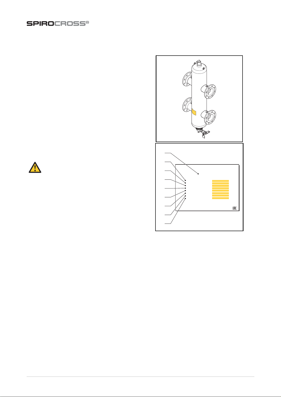
•Apply the separately supplied product labels if the
labels on the product are not visible; for instance
after the unit has been insulated.
•Make sure that there is enough space to replace the
dry pocket at the bottom (Xr). Refer to section 3.4.
•The lifting lugs may only be used during the
installation.
•The unit operates independent of the flow
direction.
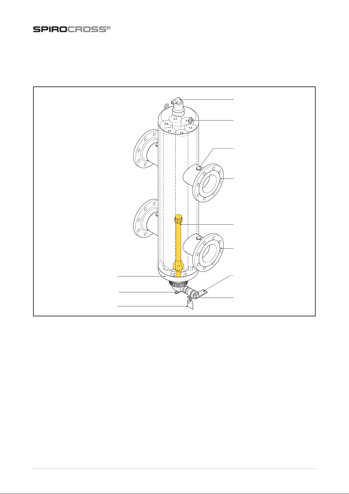
•Do not obstruct the automatic air vent and make
sure that the automatic air vent is always easily
accessible.
•A tube can be fitted to the air vent to lead away the
released (smelly) air. Excessive dirt particles or foam
forming might cause a temporary leakage of the
automatic air vent.
•The unit (except DN50 and DN65) has a sensor port
(G½") at every branch. These sensor ports are
blinded. Sensors can be mounted by removing the
blind plug from the ports. Make sure there is
enough space for mounting a sensor. The sensor
can only be fitted leak-proof with a thread sealant.
•If a drain pipe is fitted, make sure that this pipe is
fitted stress and vibration free to the drain valve.
Preferably, a flexible pipe or pipe parts should be
used (e.g. a hose).
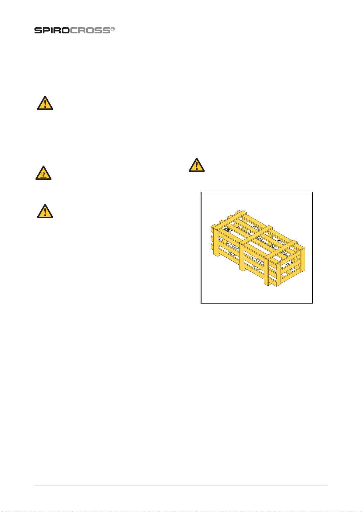
5.2 Unpack
The unit is delivered in a crate.
1. Open the crate.
2. Remove the plastic seal bag.
3. Check the unit for transport damage.
WARNING
•Installation and maintenance may only
be carried out by a qualified installer.
•When working on the unit, always
ensure there is no pressure in the
installation, let it cool down and remove
the water from the unit.
WARNING
Do not touch the unit or the pipework when
the system is in operation. The surfaces may
be hot and touching them may cause burns.
CAUTION
•Do not use the drain valve for (re)filling.
•Always install the unit vertically, with
the automatic air vent on top and the
dry pocket at the bottom.
WARNING
To prevent damage to the unit, do not hoist
the unpacked unit.