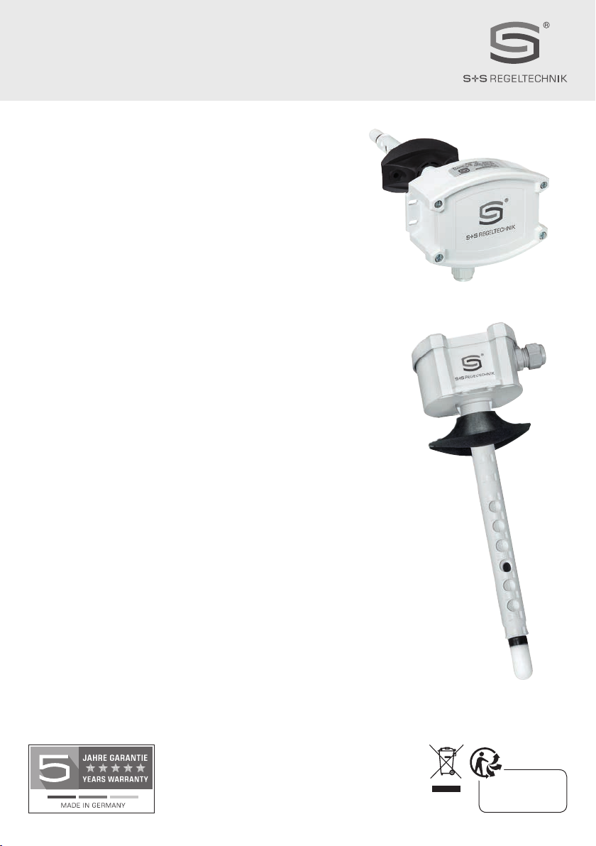
S+S Regeltechnik HYGRASREG KFTF-35 Repair manual

HYGRASREG® KFTF-35
D G F r
D
Bedienungs- und Montageanleitung
Betauungsgeschützer Kanal- Feuchte- und Temperaturfühler
für „Hochfeuchte“, inkl. Montageflansch,
kalibrierfähig, mit Mehrbereichsumschaltung,
mit aktivem und schaltenden Ausgang
G
Operating Instructions, Mounting & Installation
Condensation-protected duct humidity and temperature sensor
for “high humidity”, incl. mounting flange,
calibratable, with multi-range switching,
with active and switching output
F
Notice d’instruction
Sonde de température et d’humidité pour montage en gaine
protégée contre la condensation pour «humidité élevée»,
y compris bride de montage, étalonnable,
avec commutation multi-gamme,
avec sortie active et en tout ou rien
r
Руководство по монтажу и обслуживанию
Защищенный от образования конденсата канальный датчик
влажности и температуры для высокой влажности,
включ. присоединительный фланец, калибруемый,
с переключением между несколькими диапазонами,
с активным и релейным выходом
CART O N S
ET EMBALLAGE
PAPIER À TRIER
6000-3970-0000-1XX 39700-0000 V100 09 ⁄ 2022
S+S REGELTECHNIK GMBH
THURN-UND-TAXIS-STR. 22
90411 NÜRNBERG ⁄GERMANY
FON +49
(0)911 ⁄ 519 47-0
mail@SplusS.de
www
.
SplusS.de

2
HYGRASREG® KFTF-35
D G F r
MFT - 20 - K
Montageflansch aus Kunststoff
Mounting flange, plastic
Bride de montage en matière plastique
Присоединительный фланец из пластика
Maßzeichnung
Dimensional drawing
Plan coté
Габаритный чертеж
[mm]
SF -M
Metall -Sinterfilter (optional)
Metal sinter filter (optional)
Filtre fritté en métal (en option)
Металлокерамический фильтр (опция)
SF -K
Kunststoff -Sinterfilter (Standard)
Plastic sinter filter (standard)
Fitre fritté en matière synthétique (standard)
Пластиковым спеченным фильтром
(стандартное исполнение)
~ 200
126
112
90
50
ø 20
112
20
4
ø 32.3
13.4
~ 35
M16x1.5
60
87
~30
32
62
M4
ø5.2
ø
20
M16x1.5
~ 200
126
112
90
50
ø 20
112
20
4
ø 32.3
13.4
~ 35
M16x1.5
60
87
~30
32
62
M4
ø5.2
ø
20
M16x1.5
KFTF-35

3
DHYGRASREG®KFTF-35
Rev. Data - V20
Betauungsgeschützer Kanalfühler
HYGRASREG
®
KFTF-35
mit aktivem und schaltendem Ausgang, Gehäuse aus schlagfestem Kunststoff
mit Schnellverschlussschrauben, Kabelverschraubung, Kunststoff-Sinterfilter (austauschbar), wahlweise mit ⁄ohne Display,
zur Erfassung der relativen Feuchte (0…100 % RH) und der Temperatur (4 umschaltbare Messbereiche, max. 0...+100 °C) sowie zur Ermittlung
diverser Kenngrößen der Feuchtemesstechnik. Der Messumformer wandelt die Messgrößen in ein Normsignal von 0 -10 V oder 4...20 mA.
Das Gerät ist speziell für den Einsatz im
Hochfeuchtebereich
(95...99 % RH) konzipiert.
Es wird ein langzeitstabiler,
digitaler Feuchte- und
Temperatursensor
verwendet. Durch
Übertemperatur wird die Betauung des Feuchtesensors verhindert bzw. erschwert. Mit Hilfe eines zweiten,
separaten Temperaturmesselements wird die tatsächliche relative Feuchte der Umgebungsluft ermittelt. Aus diesen Messgrößen werden intern
folgende Kenngrößen berechnet, die über den Ausgang
OUT3
abrufbar sind: absolute Feuchte, Mischungsverhältnis, Taupunkt und Feuchtkugel-
temperatur (über DIP-Schalter umstellbar).
Der Fühler findet Einsatz in der Medizintechnik, Kältetechnik, Regeltechnik, Klima- und Reinraumtechnik.
Der Fühler ist werkseitig kalibriert, eine umgebungsbedingte Feinjustierung durch den Fachmann ist möglich.
TECHNISCHE DATEN
Spannungsversorgung: 24 V AC/DC (± 10 %)
Bürde: > 100 kOhm bei U -Variante; 100...500 Ohm bei I-Variante
Leistungsaufnahme: typisch < 6 W bei 24 V DC, Peakstrom 200 mA
Messgrößen: relative Feuchte [%RH], Temperatur [°C]
Kenngrößen: absolute Feuchte [g/m3], Mischungsverhältnis [g/kg], Taupunkt [°C], Feuchtkugeltemperatur [°C]
Ausgänge: 3 aktive Ausgänge (0 -10 V oder 4...20 mA)
1 Wechsler
Sensor:
digitaler Feuchtesensor mit integriertem Temperatursensor,
kleine Hysterese, hohe Langzeitstabilität,
mit Kondensationsschutz durch Heizfunktion
(plus ein zweites, separates Temperaturmesselement)
Sensorschutz:
Kunststoff
-Sinterfilter, Ø 16 mm, L = 35 mm, austauschbar
(optional
Metall
-Sinterfilter, Ø 16 mm, L = 32 mm)
FEUCHTE
Messbereich Feuchte: 0...100 % RH
Abweichung Feuchte: typisch ± 3,0 %
(30...70 % RH) bei +25 °C, sonst ± 3,5 %
(Abweichung der alternativen Kenngrößen ergeben sich
aus den Abweichungen von Feuchte und Temperatur.)
Ausgang Feuchte: 0 -10V bei U -Variante; 4...20 mA bei I-Variante
TEMPERATUR
Messbereich Temperatur:
Mehrbereichsumschaltung mit 4 umschaltbaren Messbereichen
(siehe Tabelle)
0...+50 °C (default); –20...+50 °C; –20...+80 °C; 0...+100 °C
Abweichung Temperatur: typisch ± 0,5 K bei +25 °C
Ausgang Temperatur: 0 -10V bei U -Variante; 4...20 mA bei I-Variante
Langzeitstabilität: ± 1 % pro Jahr
Ansprechzeit (t90): < 60 s
Einlaufzeit: < 10 min
elektrischer Anschluss: 0,14 - 1,5 mm², über Schraubklemmen
Kabelanschluss:
Kabelverschraubung
aus Kunststoff (M 16 x 1,5 ; mit Zugentlastung,
auswechselbar, max. Innendurchmesser 10,4mm)
Gehäuse: Kunststoff,
UV-beständig,
Werkstoff Polyamid, 30 % glaskugelverstärkt,
mit Schnellverschlussschrauben(Schlitz ⁄ Kreuzschlitz-Kombination),
Farbe Verkehrsweiß (ähnlich RAL 9016), Deckel für Display ist transparent!
Abmaße Gehäuse: 126 x 90 x 50 mm (Tyr 2)
Schutzrohr:
PLEUROFORM
TM, Werkstoff Polyamid (PA6), verdrehsicher,
Ø 20 mm, NL = 235 mm (optional 135 mm), vmax = 30 m/s (Luft)
Prozessanschluss: mittels Montageflansch (im Lieferumfang enthalten)
Umgebungstemperatur: Lagerung –20...+50 °C; Betrieb –20...+50 °C
zulässige Luftfeuchte: < 99 % RH, nicht kondensierende, schadstofffreie Luft
Schutzklasse: III (nach EN 60 730)
Schutzart:
IP 65
(nach EN 60 529) Gehäuse,Sensorik IP 20
Normen: CE-Konformität, elektromagnetische Verträglichkeit nach EN 61326,
EMV-Richtlinie 2014 ⁄ 30 ⁄ EU
Fortsetzung siehe nächste Seite!

4
DHYGRASREG®KFTF-35
Rev. Data - V20
TECHNISCHE DATEN (Fortsetzung)
FUNKTION
Durch eine stetige Übertemperatur des Feuchtesensors wird dessen Betauen
maßgeblich erschwert bzw. im Rahmen der Systemgrenzen verhindert.
Es wird eine schnellere Reaktionsgeschwindigkeit bei Feuchteschwankungen,
auch im Bereich oberhalb von 95 % RH erreicht. Der Sensor (kombiniertes Feuchte-
und Temperaturmesselement) wird ca. 3K über die Umgebungstemperatur aufgeheizt.
Aus der gemessenen relativen Feuchte bei Übertemperatur, der Chiptemperatur
des Sensors und der Umgebungstemperatur (über ein zweites, separates
Temperaturmesselement) wird die tatsächliche relative Feuchte ermittelt.
ZUBEHÖR
siehe Tabelle
Typ ⁄ WG01
Messbereich
Feuchte
Temperatur
Ausgang
Ausgang
Display
aktiv
schaltend
Art.-Nr.
KFTF-35 - I I - Variante
KFTF-35-I/W
0
...
100 % RH
0...20 g/m3(a.F.)
0...25 g/m3(a.F.)
0...20 g/kg (MV)
0...25 g/kg (MV)
0...+50 °C (TP)
–20...+50 °C (TP)
–30...+30 °C (
FKT
)
–20...+50 °C (FKT)
0
...
+50 °C
–20...+50 °C
–20...+80 °C
0...+100 °C
3x
4...20 mA
1x Wechsler
1201-814B-1000-000
KFTF-35-I/W
LCD
(wie oben) (wie oben) 3x
4...20 mA
1x Wechsler ■
1201-814B-1200-000
KFTF-35 - U U - Variante
KFTF-35-U/W (wie oben) (wie oben) 3x
0 -10 V
1x Wechsler
1201-814A-1000-000
KFTF-35-U/W
LCD
(wie oben) (wie oben) 3x
0 -10 V
1x Wechsler ■
1201-814A-1200-000
Optional: verkürztes Schutzrohr
PLEUROFORM
TM, L = 100 mm auf Anfrage!
Hinweis
Aus den Messgrößen werden intern
alternative
Kenngrößen
berechnet,
die über den aktiven Ausgang
OUT3
abrufbar sind:
absolute Feuchte, Mischungsverhältnis, Taupunkt und Feuchtkugeltemperatur
(über DIP-Schalter umstellbar)
ZUBEHÖR
SF-M Metall
-Sinterfilter, Ø 16 mm, L = 32 mm, austauschbar,
aus Edelstahl
V4A
(1.4 404)
7000-0050-2200-100

5
DHYGRASREG®KFTF-35
Rev. Data - V20
Schaltbild Anschlussbild
Anschlussbild
KFTF-35 - xx KFTF-35 - I
KFTF-35 - U
6
7
8
2
3
4
5
1
+UB 24V AC/DC
Ausgang Feuchte 4...20mA
Ausgang Temperatur 4...20mA
Ausgang altern. Kenngröße 4...20mA
Öffner
Schließer
Wurzel
–UB GND
6
7
8
2
3
4
5
1
+UB 24V AC/DC
Ausgang Feuchte 0-10V
Ausgang Temperatur 0-10V
Ausgang altern. Kenngröße 0-10V
Öffner
Schließer
Wurzel
–UB GND
6 7 8
NC MNO
1 2 3
UB+ GND HUM
4 5
TEMP
thershold
OUT3
123456
ON DIP
12
ON
TEMP
offset
HUM
offset
123456
ON DIP
12
ON
TEMP
offset
HUM
offset
thershold
SET-Potentiometer
Einstellung Schaltpunkt
OFFSET-Potentiometer
HUM = Feuchte (± 5 %RH)
TEMP = Temperatur (± 5 K)
LED
(on = aktiv)
Relais / Schaltpunkt überschritten
DIP
Zuordnung Relais
DIP
Mehrbereichsumschaltung Temperatur
und alternative Kenngrößen
Relais
Zuordnung
Relaisfunktion
DIP
1
DIP
2
inaktiv
(default) OFF OFF
Feuchte
O N
OFF
Temperatur OFF
O N
alternative Kenngrößen
O N O N
Messbereiche
Temperatur
DIP
1
DIP
2
0
...
+50 °C
(default)OFF OFF
–20...+50 °C
O N
OFF
–20...+80 °C OFF
O N
0...+100 °C
O N O N
Hinweis:
Nur für werkseitigen Service,
muss im Betrieb auf "OFF" gestellt sein!
DIP
6
Betrieb
(default) OFF
Messbereiche
alternative Kenngrößen
DIP
3
DIP
4
DIP
5
(a.F.)
0
...
20 g/m3
(default)OFF OFF OFF
(a.F.) 0...25 g/m3
O N
OFF OFF
(MV) 0...20 g/kg OFF
O N
OFF
(MV) 0...25 g/kg
O N O N
OFF
(TP) 0...+50 °C OFF OFF
O N
(TP) –20...+50 °C
O N
OFF
O N
(FKT) –30...+30 °C OFF
O N O N
(FKT) –20...+50 °C
O N O N O N
(a.F.) = absolute Feuchte [g/m3]
(MV) = Mischungsverhältnis [g/kg]
(TP) = Taupunkt [°C]
(FKT) = Feuchtkugeltemperatur [°C]
Typ ⁄ WG01
Messbereich
Feuchte
Temperatur
Ausgang
Ausgang
Display
aktiv
schaltend
Art.-Nr.
KFTF-35 - I I - Variante
KFTF-35-I/W
0
...
100 % RH
0...20 g/m3(a.F.)
0...25 g/m3(a.F.)
0...20 g/kg (MV)
0...25 g/kg (MV)
0...+50 °C (TP)
–20...+50 °C (TP)
–30...+30 °C (
FKT
)
–20...+50 °C (FKT)
0
...
+50 °C
–20...+50 °C
–20...+80 °C
0...+100 °C
3x
4...20 mA
1x Wechsler
1201-814B-1000-000
KFTF-35-I/W
LCD
(wie oben) (wie oben) 3x
4...20 mA
1x Wechsler ■
1201-814B-1200-000
KFTF-35 - U U - Variante
KFTF-35-U/W (wie oben) (wie oben) 3x
0 -10 V
1x Wechsler
1201-814A-1000-000
KFTF-35-U/W
LCD
(wie oben) (wie oben) 3x
0 -10 V
1x Wechsler ■
1201-814A-1200-000
Optional: verkürztes Schutzrohr
PLEUROFORM
TM, L = 100 mm auf Anfrage!
Hinweis
Aus den Messgrößen werden intern
alternative
Kenngrößen
berechnet,
die über den aktiven Ausgang
OUT3
abrufbar sind:
absolute Feuchte, Mischungsverhältnis, Taupunkt und Feuchtkugeltemperatur
(über DIP-Schalter umstellbar)
ZUBEHÖR
SF-M Metall
-Sinterfilter, Ø 16 mm, L = 32 mm, austauschbar,
aus Edelstahl
V4A
(1.4 404)
7000-0050-2200-100

6
D
Montage und Inbetriebnahme
Schaltbild
Parallelbetrieb
Schaltbild
Einzelbetrieb
VERSORGUNGSSPANNUNG:
Als Verpolungsschutz der Betriebsspannung ist bei dieser Gerätevariante
eine Einweggleichrichtung bzw. Verpolungschutzdiode integriert. Diese
interne Einweggleichrichtung erlaubt auch den Betrieb mit AC-Versorgungs-
spannung.
Das Ausgangssignal ist mit einem Messgerät abzugreifen. Hierbei wird
das Ausgangssignal gegen das Nullpotenial (O V) der Eingangsspannung
gemessen!
Wird dieses Gerät mit
DC - Versorgungsspannung
betrieben, ist der
Betriebsspannungseingang UB+ für 15...36 V DC - Einspeisung und UB–
bzw. GND als Masseleitung zu verwenden!
Werden mehrere Geräte von einer 24 V
AC - Spannung
versorgt, ist
darauf zu achten, dass alle „positiven“ Betriebsspannungseingänge (+) der
Feldgeräte miteinander verbunden sind, sowie alle „negativen“ Betriebs-
spannungseingänge (–) = Bezugspotential miteinander verbunden sind
(phasengleicher Anschluss der Feldgeräte). Alle Feldgeräteausgänge
müssen auf das gleiche Potential bezogen werden!
Bei Verpolung der Versorgungsspannung an einem der Feldgeräte würde
über dieses ein Kurzschluss der Versorgungsspannung erzeugt. Der somit
über dieses Feldgerät fließende Kurzschlussstrom kann zur Beschädigung
dieses Gerätes führen.
Achten Sie daher auf die korrekte Verdrahtung!
Schaltung Schaltung
0-10V
0V/GND
0-10V
0V/GND
Versorgung mit
AC 24V~ 0V
DC 15-36V = GND
AC 24V~ 0V
DC 15-36V = GND
Schaltung
0-10V
0V/GND
V
Versorgung mit
Temperaturtabelle
MB: 0...+100 °C
°C UA
[V]
IA
[mA]
0
0,0 4,0
5
0,5 4,8
10
1,0 5,6
15
1,5 6,4
20
2,0 7,2
25
2,5 8,0
30
3,0 8,8
35
3,5 9,6
40
4,0 10,4
45
4,5 11,2
50
5,0 12,0
55
5,5 12,8
60
6,0 13,6
65
6,5 14,4
70
7,0 15,2
75
7,5 16,0
80
8,0 16,8
85
8,5 17,6
90
9,0 18,4
95
9,5 19,2
100
10,0 20,0
Feuchtetabelle
MB: 0...100 % RH
%
RH
UA
[V]
IA
[mA]
0
0,0 4,0
5
0,5 4,8
10
1,0 5,6
15
1,5 6,4
20
2,0 7,2
25
2,5 8,0
30
3,0 8,8
35
3,5 9,6
40
4,0 10,4
45
4,5 11,2
50
5,0 12,0
55
5,5 12,8
60
6,0 13,6
65
6,5 14,4
70
7,0 15,2
75
7,5 16,0
80
8,0 16,8
85
8,5 17,6
90
9,0 18,4
95
9,5 19,2
100
10,0 20,0
Temperaturtabelle
MB: 0...+50 °C
°C UA
[V]
IA
[mA]
0
0,0 4,0
5
1,0 5,6
10
2,0 7,2
15
3,0 8,8
20
4,0 10,4
25
5,0 12,0
30
6,0 13,6
35
7,0 15,2
40
8,0 16,8
45
9,0 18,4
50
10,0 20,0
Temperaturtabelle
MB: –20...+80 °C
°C UA
[V]
IA
[mA]
– 20
0,0 4,0
– 15
0,5 4,8
– 10
1,0 5,6
– 5
1,5 6,4
0
2,0 7,2
5
2,5 8,0
10
3,0 8,8
15
3,5 9,6
20
4,0 10,4
25
4,5 11,2
30
5,0 12,0
35
5,5 12,8
40
6,0 13,6
45
6,5 14,4
50
7,0 15,2
55
7,5 16,0
60
8,0 16,8
65
8,5 17,6
70
9,0 18,4
75
9,5 19,2
80
10,0 20,0
Temperaturtabelle
MB: –20...+50 °C
°C UA
[V]
IA
[mA]
– 20
0,0 4,0
– 15
0,7 5,1
– 10
1,4 6,3
– 5
2,1 7,4
0
2,9 8,6
5
3,6 9,7
10
4,3 10,9
15
5,0 12,0
20
5,7 13,1
25
6,4 14,3
30
7,1 15,4
35
7,9 16,6
40
8,6 17,7
45
9,3 18,9
50
10,0 20,0

7
DWichtige Hinweise
Als AGB gelten ausschließlich unsere sowie die gültigen „Allgemeinen Lieferbedingungen für Erzeugnisse und Leistungen der Elektroindustrie“
(ZVEI Bedingungen) zuzüglich der Ergänzungsklausel „Erweiterter Eigentumsvorbehalt“.
Außerdem sind folgende Punkte zu beachten:
– Vor der Installation und Inbetriebnahme ist diese Anleitung zu lesen und die alle darin gemachten Hinweise sind zu beachten!
– Der Anschluss der Geräte darf nur an Sicherheitskleinspannung und im spannungslosen Zustand erfolgen. Um Schäden und Fehler am Gerät
(z.B. durch Spannungsinduktion) zu verhindern, sind abgeschirmte Leitungen zu verwenden, eine Parallelverlegung zu stromführenden Leitungen
zu vermeiden und die EMV- Richtlinien zu beachten.
– Dieses Gerät ist nur für den angegebenen Verwendungszweck zu nutzen, dabei sind die entsprechenden Sicherheitsvorschriften des VDE,
der Länder, ihrer Überwachungsorgane, des TÜV und der örtlichen EVU zu beachten.
Der Käufer hat die Einhaltung der Bau- und Sicherungsbestimmung zu gewährleisten und Gefährdungen aller Art zu vermeiden.
– Für Mängel und Schäden, die durch unsachgemäße Verwendung dieses Gerätes entstehen,
werden keinerlei Gewährleistungen und Haftungen übernommen.
– Folgeschäden, welche durch Fehler an diesem Gerät entstehen, sind von der Gewährleistung und Haftung ausgeschlossen.
– Montage und Inbetriebnahme der Geräte darf nur durch Fachpersonal erfolgen.
– Es gelten ausschließlich die technischen Daten und Anschlussbedingungen der zum Gerät gelieferten Montage- und Bedienungsanleitung,
Abweichungen zur Katalogdarstellung sind nicht zusätzlich aufgeführt und im Sinne des technischen Fortschritts und der stetigen Verbesserung
unserer Produkte möglich.
– Bei Veränderungen der Geräte durch den Anwender entfallen alle Gewährleistungsansprüche.
– Dieses Gerät darf nicht in der Nähe von Wärmequellen (z.B. Heizkörpern) oder deren Wärmestrom eingesetzt werden,
eine direkte Sonneneinstrahlung oder Wärmeeinstrahlung durch ähnliche Quellen (starke Leuchte, Halogenstrahler) ist unbedingt zu vermeiden.
– Der Betrieb in der Nähe von Geräten, welche nicht den EMV- Richtlinien entsprechen, kann zur Beeinflussung der Funktionsweise führen.
– Dieses Gerät darf nicht für Überwachungszwecke, welche dem Schutz von Personen gegen Gefährdung oder Verletzung dienen und
nicht als Not-Aus-Schalter an Anlagen und Maschinen oder vergleichbare sicherheitsrelevante Aufgaben verwendet werden.
– Die Gehäuse- und Gehäusezubehörmaße können geringe Toleranzen zu den Angaben dieser Anleitung aufweisen.
– Veränderungen dieser Unterlagen sind nicht gestattet.
– Reklamationen werden nur vollständig in Originalverpackung angenommen.
Hinweise zur Inbetriebnahme:
Dieses Gerät wurde unter genormten Bedingungen kalibriert, abgeglichen und geprüft. Bei Betrieb unter abweichenden Bedingungen empfehlen wir
Vorort eine manuelle Justage erstmals bei Inbetriebnahme sowie anschließend in regelmäßigen Abständen vorzunehmen.
Eine Inbetriebnahme ist zwingend durchzuführen und darf nur von Fachpersonal vorgenommen werden!
Vor der Montage und Inbetriebnahme ist diese Anleitung zu lesen und die alle darin gemachten Hinweise sind zu beachten!
– Dieses Gerät darf nur in schadstofffreier, nicht kondensierender Luft, ohne Über- oder Unterdruck am Sensorelement eingesetzt werden.
– Bei Aussen- und Kanalfühlern schützt der Sinterfilter des Sensorelementes den Feuchtesensor vor eventuellen Staubbelastungen.
Dieser Filter sollte bei Verunreinigung ⁄ Verschmutzung regelmäßig gewartet werden.
– Staub- und Verunreinigungen verfälschen das Messergebnis und sind zu vermeiden.
Geringe Verunreinigungen und Staubablagerungen können mit Druckluft beseitigt werden.
– Das Berühren des Feuchteelementes ist unbedingt zu vermeiden, da dies zu erheblichen Fehlmessungen führt.
– Bei Verunreinigungen empfehlen wir eine werksseitige Reinigung und Neukalibrieung.
– Chemikalien oder andere Reinigungsmittel dürfen unter keinen Umständen auf den Sensor gelangen.
– Die relative Feuchte von 0 ...100 % wird durch das Ausgangssignal 0 -10 V abgebildet. Der Arbeitsbereich des Gerätes umfasst 10,0... 99 % RH,
ausserhalb dieses Bereiches kann es zu Fehlmessungen bzw. zu erhöhten Abweichungen kommen.
–
Beim Anschluss mehrerer Fühler (0 -10 V) an eine gemeinsame Spannungsversorgung mit 24 V AC (Wechselspannung) ist auf die Polung zu achten,
da sonst die Wechselspannungsquelle kurz geschlossen werden kann.
– Die Spannungsausgänge sind kurzschlussfest, ein Anlegen einer Überspannung oder der Spannungsversorgung am Spannungsausgang zerstört
das Gerät.
– Beim Betrieb des Gerätes ausserhalb des Spezifikationsbereiches entfallen alle Garantieansprüche.

8
GHYGRASREG®KFTF-35
Rev. Data - V20
Condensation-protected ductsensor
HYGRASREG
®
KFTF-35
with active and switching output, housing made of impact-resistant plastic
with quick-locking screws, cable gland, plastic sinter filter (replaceable), optionally with ⁄ without display, for detecting relative humidity
(0…100 % RH) and temperature (4 switchable measuring ranges, max. 0...+100°C) as well as for determining various parameters of humidity
measurement technology. The measuring transducer converts the measured variables into a standard signal of 0-10V or 4…20 mA.
The unit is specially designed for use in the
high humidity range
(95…99% RH).
A long-term stable,
digital humidity and temperature sensor
is
used. Overtemperature
prevents or hinders dew formation on the humidity sensor. A second, separate temperature measuring element is used to
determine the actual relative humidity of the ambient air. The following measured variables are calculated internally from these parameters and are
retrievable via output
OUT3
: absolute humidity, mixing ratio, dew point and wet bulb temperature (can be changed via DIP switch).
The sensor is used in medical technology, refrigeration technology, control technology, air conditioning and clean room technology.
The sensor is factory-calibrated; an environmental precision adjustment by an expert is possible.
TECHNICAL DATA
Power supply: 24 V AC/DC (± 10%)
Working resistance: > 100 kOhm for U variant; 100…500 Ohm for I variant
Power consumption: typically < 6 W at 24 V DC, peak current 200 mA
Measured variables: relative humidity [% RH], temperature [°C]
Parameters: absolute humidity [g/m3], mixture ratio [g/kg], dew point [°C], wet bulb temperature [°C]
Outputs: 3 active outputs (0 -10 V or 4…20 mA)
1 changeover contact
Sensor:
digital humidity sensor with integrated temperature sensor,
low hysteresis, high long-term stability,
with condensation protection through heating function
(plus a second, separate temperature measuring element)
Sensor protection:
plastic
sinter filter, Ø 16 mm, L = 35 mm, exchangeable
(optional
metal
sinter filter, Ø 16 mm, L = 32 mm)
HUMIDITY
Measuring range, humidity: 0…100% RH
Deviation in humidity: typically ± 3.0%
(30…70% RH) at +25 °C, otherwise ± 3.5%
(deviations of alternative parameters result
from deviations from humidity and temperature.)
Output humidity: 0 -10V for U variant; 4…20 mA for I variant
TEMPERATURE
Temperature measuring range:
Multi-range switching with 4 switchable measuring ranges
(see table)
0...+50 °C (default); –20...+50 °C; –20...+80 °C; 0...+100 °C
Deviation in temperature: typically ± 0.5 K at +25 °C
Temperature output: 0 -10V for U variant; 4…20 mA for I variant
Long-term stability: ± 1% per year
Response time (t90): < 60 s
Warm-up time: < 10 min
Electrical connection: 0.14 - 1.5 mm², via terminal screws
Cable connection:
Cable gland,
plastic (M 16x 1.5; with strain relief,
exchangeable, max. inner diameter 10.4 mm)
Housing: Plastic,
UV-resistant,
material polyamide, 30% glass-globe reinforced,
with quick-locking screws(slotted ⁄ Phillips head combination),
colour traffic white (similar to RAL 9016), enclosure cover for display is transparent!
Housing dimensions: 126 x 90 x 50 mm (Tyr 2)
Protective tube:
PLEUROFORM
TM, material polyamide (PA6), with torsion protection,
Ø 20 mm, NL = 235 mm (optional 135 mm), vmax = 30 m/s (air)
Process connection: by means of plastic mounting flange (included in the scope of delivery)
Ambient temperature: storage –20...+50 °C; operation –20...+50 °C
Permitted humidity: < 99% RH, non-precipitating air free of harmful substances
Protection class: III (as per EN 60 730)
IP rating:
IP 65
(as per EN 60 529) housing,IP 20 sensor technology
Standards: CE-conformity, electromagnetic compatibility according to EN 61 326,
EMC Directive 2014 ⁄ 30 ⁄ EU
continued on next page!

9
GHYGRASREG®KFTF-35
Rev. Data - V20
TECHNICAL DATA (continued)
FUNCTION
A constant overtemperature of the humidity sensor makes its dewing considerably
more difficult or prevents its formation within the limits of the system.
A faster reaction speed is achieved in the case of humidity fluctuations, even in the
range above
95 % RH
. The sensor (combined humidity and temperature measuring
element) is heated approx. 3K above the ambient temperature.
The actual relative humidity is determined from the measured relative humidity at
overtemperature, the chip temperature of the sensor and the ambient temperature
(via a second, separate temperature measuring element).
ACCESSORIES
see table
Type ⁄ WG01
Measuring Range
Humidity
Temperature
Output
Output
Display
active
switching
Item No.
KFTF-35 - I I variant
KFTF-35-I/W
0
...
100 % RH
0...20 g/m3(a.F.)
0...25 g/m3(a.F.)
0...20 g/kg (MV)
0...25 g/kg (MV)
0...+50 °C (TP)
–20...+50 °C (TP)
–30...+30 °C (
FKT
)
–20...+50 °C (FKT)
0
...
+50 °C
–20...+50 °C
–20...+80 °C
0...+100 °C
3x
4...20 mA
1x Changeover
contact
1201-814B-1000-000
KFTF-35-I/W
LCD
(as above) (as above) 3x
4...20 mA
1x Changeover
contact ■
1201-814B-1200-000
KFTF-35 - U U variant
KFTF-35-U/W (as above) (as above) 3x
0 -10 V
1x Changeover
contact
1201-814A-1000-000
KFTF-35-U/W
LCD
(as above) (as above) 3x
0 -10 V
1x Changeover
contact ■
1201-814A-1200-000
Optional: shortened protection tube
PLEUROFORM
TM L = 100 mm on request
Note Alternative
parameters
are calculated internally from the measured variables,
which are retrievable via the active output
OUT3
:
absolute humidity, mixing ratio, dew point and wet bulb temperature
(can be changed via DIP switch)
ACCESSORIES
SF-M Metal
sinter filter, Ø 16 mm, L = 32 mm, exchangeable
stainless steel
V4A
(1.4 404)
7000-0050-2200-100

10
GHYGRASREG®KFTF-35
Rev. Data - V20
Schematic diagram Connecting diagram
Connecting diagram
KFTF-35 - xx KFTF-35 - I
KFTF-35 - U
6
7
8
2
3
4
5
1
NC Normally Closed
NO Normally Open
M Common
+UB 24V AC/DC
Output Humidity 4...20mA
Output Temperature 4...20mA
Output altern. parameters 4...20mA
–UB GND
6
7
8
2
3
4
5
1
NC Normally Closed
NO Normally Open
M Common
+UB 24V AC/DC
Output Humidity 0-10V
Output Temperature 0-10V
Output altern. parameters 0-10V
–UB GND
6 7 8
NC MNO
1 2 3
UB+ GND HUM
4 5
TEMP
thershold
OUT3
123456
ON DIP
12
ON
TEMP
offset
HUM
offset
123456
ON DIP
12
ON
TEMP
offset
HUM
offset
thershold
SET potentiometer
setting switching point
OFFSET potentiometer
HUM = humidity (± 5 %RH)
TEMP = temperature (± 5 K)
LED
(on =
active
)
relay / switching point exceeded
DIP
assignment relay
DIP
multi-range switching temperature
and alternative parameters
Relay
Type ⁄ WG01
Measuring Range
Humidity
Temperature
Output
Output
Display
active
switching
Item No.
KFTF-35 - I I variant
KFTF-35-I/W
0
...
100 % RH
0...20 g/m3(a.F.)
0...25 g/m3(a.F.)
0...20 g/kg (MV)
0...25 g/kg (MV)
0...+50 °C (TP)
–20...+50 °C (TP)
–30...+30 °C (
FKT
)
–20...+50 °C (FKT)
0
...
+50 °C
–20...+50 °C
–20...+80 °C
0...+100 °C
3x
4...20 mA
1x Changeover
contact
1201-814B-1000-000
KFTF-35-I/W
LCD
(as above) (as above) 3x
4...20 mA
1x Changeover
contact ■
1201-814B-1200-000
KFTF-35 - U U variant
KFTF-35-U/W (as above) (as above) 3x
0 -10 V
1x Changeover
contact
1201-814A-1000-000
KFTF-35-U/W
LCD
(as above) (as above) 3x
0 -10 V
1x Changeover
contact ■
1201-814A-1200-000
Optional: shortened protection tube
PLEUROFORM
TM L = 100 mm on request
Note Alternative
parameters
are calculated internally from the measured variables,
which are retrievable via the active output
OUT3
:
absolute humidity, mixing ratio, dew point and wet bulb temperature
(can be changed via DIP switch)
ACCESSORIES
SF-M Metal
sinter filter, Ø 16 mm, L = 32 mm, exchangeable
stainless steel
V4A
(1.4 404)
7000-0050-2200-100
Relay function
assignment
DIP
1
DIP
2
inactive
(default) OFF OFF
Humidity
O N
OFF
Temperature OFF
O N
alternative parameters
O N O N
Measuring ranges
temperature
DIP
1
DIP
2
0
...
+50 °C
(default)OFF OFF
–20...+50 °C
O N
OFF
–20...+80 °C OFF
O N
0...+100 °C
O N O N
Note:
For factory service only,
it must be set to "OFF" during operation!
DIP
6
Operation
(default) OFF
Measuring ranges
alternative parameters
DIP
3
DIP
4
DIP
5
(a.F.)
0
...
20 g⁄m3
(default)OFF OFF OFF
(a.F.) 0...25 g/m3
O N
OFF OFF
(MV) 0...20 g/kg OFF
O N
OFF
(MV) 0...25 g/kg
O N O N
OFF
(TP) 0...+50 °C OFF OFF
O N
(TP) –20...+50 °C
O N
OFF
O N
(FKT) –30...+30 °C OFF
O N O N
(FKT) –20...+50 °C
O N O N O N
(a.F.) = absolute humidity [g/m3]
(MV) = mixture ratio [g/kg]
(TP) = dew point [°C]
(FKT) = wet bulb temperature [°C]

11
G
Installation and Commissioning
Connecting scheme
Parallel operation
Connecting scheme
Individual operation
Circuitry Circuitry
0...10V
0V/GND
0...10V
0V/GND
Power supply
AC 24V~ 0V
DC 15-36V = GND
Circuitry
0...10V
0V/GND
V
Power supply
AC 24V~ 0V
DC 15-36V = GND
SUPPLY VOLTAGE :
For operating voltage reverse polarity protection, a one-way rectifier or
reverse polarity protection diode is integrated in this device variant.
This internal one-way rectifier on AC supply voltage.
The output signal is to be tapped by a measuring instrument. The output
signal is measured her against zero potential (O V) of the input voltage!
When this device is operated on
DC supply voltage
, the operating voltage
input UB+ is to be used for 15...36 V DC supply and UB – or GND for
ground wire!
When several devices are supplied by one 24 V
AC voltage supply
, it is to
be ensured that all ”positive“ operating voltage input terminals (+) of the
field devices are connected with each other and all ”negative“ operating
voltage input terminals (–) (= reference potential) are connected together
(in-phase connection of field devices). All outputs of field devices must be
referenced to the same potential!
In case of reversed polarity at one field device, a supply voltage short-
circuit would be caused by that device. The consequential short-circuit
current flowing through this field device may cause damage to it.
Therefore, pay attention to correct wiring!
Temperature table
MR: 0...+100 °C
°C UA
[V]
IA
[mA]
0
0.0 4.0
5
0.5 4.8
10
1.0 5.6
15
1.5 6.4
20
2.0 7.2
25
2.5 8.0
30
3.0 8.8
35
3.5 9.6
40
4.0 10.4
45
4.5 11.2
50
5.0 12.0
55
5.5 12.8
60
6.0 13.6
65
6.5 14.4
70
7.0 15.2
75
7.5 16.0
80
8.0 16.8
85
8.5 17.6
90
9.0 18.4
95
9.5 19.2
100
10.0 20.0
Humidity table
MR: 0...100 % RH
%
RH
UA
[V]
IA
[mA]
0
0.0 4.0
5
0.5 4.8
10
1.0 5.6
15
1.5 6.4
20
2.0 7.2
25
2.5 8.0
30
3.0 8.8
35
3.5 9.6
40
4.0 10.4
45
4.5 11.2
50
5.0 12.0
55
5.5 12.8
60
6.0 13.6
65
6.5 14.4
70
7.0 15.2
75
7.5 16.0
80
8.0 16.8
85
8.5 17.6
90
9.0 18.4
95
9.5 19.2
100
10.0 20.0
Temperature table
MR: 0...+50 °C
°C UA
[V]
IA
[mA]
0
0.0 4.0
5
1.0 5.6
10
2.0 7.2
15
3.0 8.8
20
4.0 10.4
25
5.0 12.0
30
6.0 13.6
35
7.0 15.2
40
8.0 16.8
45
9.0 18.4
50
10.0 20.0
Temperature table
MR: –20...+80 °C
°C UA
[V]
IA
[mA]
– 20
0.0 4.0
– 15
0.5 4.8
– 10
1.0 5.6
– 5
1.5 6.4
0
2.0 7.2
5
2.5 8.0
10
3.0 8.8
15
3.5 9.6
20
4.0 10.4
25
4.5 11.2
30
5.0 12.0
35
5.5 12.8
40
6.0 13.6
45
6.5 14.4
50
7.0 15.2
55
7.5 16.0
60
8.0 16.8
65
8.5 17.6
70
9.0 18.4
75
9.5 19.2
80
10.0 20.0
Temperature table
MR: –20...+50 °C
°C UA
[V]
IA
[mA]
– 20
0.0 4.0
– 15
0.7 5.1
– 10
1.4 6.3
– 5
2.1 7.4
0
2.9 8.6
5
3.6 9.7
10
4.3 10.9
15
5.0 12.0
20
5.7 13.1
25
6.4 14.3
30
7.1 15.4
35
7.9 16.6
40
8.6 17.7
45
9.3 18.9
50
10.0 20.0

12
Our “General Terms and Conditions for Business“ together with the “General Conditions for the Supply of Products and Services of the
Electrical and Electronics Industry“ (ZVEI conditions) including supplementary clause “Extended Retention of Title“ apply as the exclusive
terms and conditions.
In addition, the following points are to be observed:
– These instructions must be read before installation and putting in operation and all notes provided therein are to be regarded!
– Devices must only be connected to safety extra-low voltage and under dead-voltage condition. To avoid damages and errors at the device
(e.g. by voltage induction) shielded cables are to be used, laying parallel with current-carrying lines is to be avoided,
and EMC directives are to be observed.
– This device shall only be used for its intended purpose. Respective safety regulations issued by the VDE, the states, their control authorities,
the TÜV and the local energy supply company must be observed. The purchaser has to adhere to the building and safety regulations and has to
prevent perils of any kind.
– No warranties or liabilities will be assumed for defects and damages arising from improper use of this device.
– Consequential damages caused by a fault in this device are excluded from warranty or liability.
– These devices must be installed and commissioned by authorised specialists.
– The technical data and connecting conditions of the mounting and operating instructions delivered together with the device are exclusively valid.
Deviations from the catalogue representation are not explicitly mentioned and are possible in terms of technical progress and continuous
improvement of our products.
– In case of any modifications made by the user, all warranty claims are forfeited.
– This device must not be installed close to heat sources (e.g. radiators) or be exposed to their heat flow.
Direct sun irradiation or heat irradiation by similar sources (powerful lamps, halogen spotlights) must absolutely be avoided.
– Operating this device close to other devices that do not comply with EMC directives may influence functionality.
– This device must not be used for monitoring applications, which serve the purpose of protecting persons against hazards or injury,
or as an EMERGENCY STOP switch for systems or machinery, or for any other similar safety-relevant purposes.
– Dimensions of housings or housing accessories may show slight tolerances on the specifications provided in these instructions.
– Modifications of these records are not permitted.
– In case of a complaint, only complete devices returned in original packing will be accepted.
Notes on commissioning:
This device was calibrated, adjusted and tested under standardised conditions. When operating under deviating conditions,
we recommend performing an initial manual adjustment on-site during commissioning and subsequently at regular intervals.
Commissioning is mandatory and may only be performed by qualified personnel!
These instructions must be read before installation and commissioning and all notes provided therein are to be regarded!
GGeneral notes
– This unit must only be used in non-precipitating air without positive or negative pressure at the sensor element.
– With outdoor and duct sensors, the sinter filter of the sensor element protects the humidity sensor against potential dust exposure.
In case of contamination/soiling, this filter should be cleaned on a regular basis.
– Dust and contamination distort measurement results and are to be avoided.
Small amounts of contamination and dust deposits can be removed using compressed air.
– Touching the humidity element must be avoided under any circumstances, since this would result in serious measuring errors.
– In case of contamination, we recommend cleaning and recalibration in the factory.
– Under no circumstances should the sensor come into contact with chemicals or other cleaning agents.
– The relative humidity of 0 …100 % is represented by the output signal of 0-10V. The operating range of the unit covers 10.0…99% RH,
; faulty measurements or increased deviations may occur outside that range.
–
When several sensors (0-10V)are connected to one voltage supply of 24 V AC (alternating voltage), the correct polarity must be ensured
as
otherwise the alternating voltage source may be short-circuited.
– The voltage outputs are short-circuit proof; applying overvoltage or voltage supply to the voltage output will destroy the unit.
– If this unit is operated outside the specified range, all warranty claims are forfeited.

13
FHYGRASREG®KFTF-35
Rev. Data - V20
Sonde de mesure pour montage en gaine protégée contre la condensation
HYGRASREG
®
KFTF-35
avec sortie active et en tout ou rien,
avec boîtier en plastique résistante aux chocs et vis de fermeture rapide, presse-étoupe, filtre fritté en plastique (remplaçable), au choix avec/sans
écran, pour détecter l’humidité relative (0...100% RH) et la température (4plages de mesure commutables, max. 0...+100 °C) et pour déterminer
divers paramètres caractéristiques de la technique de mesure de l’humidité. Le convertisseur de mesure convertit les grandeurs de mesure en un
signal normalisé de 0...10V ou de 4...20mA.
L’appareil est spécialement conçu pour une utilisation dans une
plage d’humidité élevée
(95...99% RH).
Un capteur
numérique d’humidité et de
température,
stable à long terme,
est utilisé. La surchauffe
empêche ou complique la formation de condensation sur le capteur d’humidité.
L’humidité relative réelle de l’air ambiant est déterminée à l’aide d’un deuxième élément de mesure de la température séparé.
Les paramètres suivants, consultables sur la sortie
OUT3
, sont calculés en interne à partir ces grandeurs de mesure:
humidité absolue, rapport de mélange et température de bulbe humide (commutable via un interrupteur DIP).
La sonde est utilisée dans la technique médicale, la technique frigorifique, la technique de régulation, la technique de climatisation et de salles
blanches. La sonde est étalonnée d’usine et peut être ajustée plus précisément à son environnement par un professionnel.
CARACTÉRISTIQUES TECHNIQUES
Alimentation en tension: 24V AC/CC (± 10%)
Charge: > 100kOhm pour la variante U; 100...500Ohm pour la variante I
Puissance absorbée: typique < 6W pour 24VCC, pointe de courant 200mA
Grandeurs de mesure: humidité relative [%RH], température [°C]
Paramètres: humidité absolue [g/m3], rapport de mélange [g/kg], point de rosée [°C], température de bulbe humide [°C]
Sorties: 3sorties actives (0...10V ou 4...20mA)
1inverseur
Capteur:
capteur d’humidité numérique avec capteur de température intégré,
petite hystérésis, haute stabilité à long terme,
avec protection contre la condensation grâce à la fonction de chauffage
(plus un deuxième élément de mesure de la température séparé)
Protection de capteur: filtre fritté en
plastique
, Ø 16 mm, L = 35 mm, remplaçable
(en option filtre fritté en
métal
, Ø 16 mm, L = 32 mm)
HUMIDITÉ
Plage de mesure humidité: 0...100% RH
Écart humidité: typique ± 3,0%
(30...70% HR) à +25°C, sinon ± 3,5%
(L’écart des paramètres alternatifs résulte
des écarts de l’humidité et de la température.)
Sortie humidité: 0 -10V pour variante U; 4...20mA pour variante I
TEMPÉRATURE
Plage de mesure température
:
commutation multi-gamme avec 4plages de mesure commutables
(voir tableau)
0...+50°C (par défaut); –20...+50 °C; –20...+80 °C; 0...+100 °C
Écart température: typique ± 0,5 K à +25 °C
Sortie température: 0 -10V pour variante U; 4...20mA pour variante I
Stabilité à long terme: ± 1% par an
Temps de réponse (t90): < 60s
Temps de démarrage: < 10 min
Raccordement électrique: 0,14 - 1,5 mm², par bornes à vis
Raccordement de câble:
presse-étoupe
en plastique (M 16x 1,5; avec décharge de traction,
remplaçable, diamètre intérieur max. 10,4mm)
Boîtier: plastique,
résistant aux UV
, matière polyamide, renforcé de billes de verre à 30 %,
avec vis de fermeture rapide (association fente/fente en croix),
couleur blanc signalisation (similaire à RAL 9016),
le couvercle de l’écran est transparent!
Dimensions du boîtier: 126 x 90 x 50 mm (Tyr 2)
Tube de protection:
PLEUROFORM
TM, matière polyamide (PA6), avec protection contre la torsion,
Ø 20mm, NL = 235 mm (optional 135 mm), vmax = 30m/s (air)
Raccordement process: avec bride de montage (comprise dans la livraison)
Température ambiante: stockage –20...+50 °C; fonctionnement –20...+50 °C
Humidité de l’air admissible: < 99% RH, air non pollué sans condensation
Classe de protection: III (selon EN60730)
Type de protection: boîtier
IP 65
(selon EN60529), capteurs IP 20
Normes: Conformité CE, compatibilité électromagnétique selon EN 61 326,
Directive «CEM» 2014 ⁄ 30 ⁄ EU
continued on next page!

14
FHYGRASREG®KFTF-35
Rev. Data - V20
CARACTÉRISTIQUES TECHNIQUES (continued)
FONCTION
Une surchauffe constante de la sonde d’humidité rend la formation de condensation
beaucoup plus difficile et peut même l’empêcher dans les limites du système.
On obtient une vitesse de réaction plus rapide en cas de variations d’humidité,
même dans une plage supérieure à 95 % RH. Le capteur (élément de mesure combiné
de l’humidité et de la température) est chauffé à environ 3K au-dessus de la température
ambiante. L’humidité relative réelle est déterminée à partir de l’humidité relative mesurée
en cas de surchauffe, de la température de la puce du capteur et de la température
ambiante (via un deuxième élément de mesure de la température séparé).
ACCESSOIRES
voir tableau
Type ⁄ WG01 plage de mesure
humidité
température
sortie
sortie
écran
active
en tout ou rien
référence
KFTF-35 - I variante I
KFTF-35-I/W
0
...
100 % RH
0...20 g/m3(a.F.)
0...25 g/m3(a.F.)
0...20 g/kg (MV)
0...25 g/kg (MV)
0...+50 °C (TP)
–20...+50 °C (TP)
–30...+30 °C (
FKT
)
–20...+50 °C (FKT)
0
...
+50 °C
–20...+50 °C
–20...+80 °C
0...+100 °C
3x
4...20 mA
1x inverseur
1201-814B-1000-000
KFTF-35-I/W
LCD
(comme plus haut) (comme plus haut) 3x
4...20 mA
1x inverseur ■
1201-814B-1200-000
KFTF-35 - U variante U
KFTF-35-U/W (comme plus haut) (comme plus haut) 3x
0 -10 V
1x inverseur
1201-814A-1000-000
KFTF-35-U/W
LCD
(comme plus haut) (comme plus haut) 3x
0 -10 V
1x inverseur ■
1201-814A-1200-000
En option : tube de protection raccourci
PLEUROFORM
TM,L = 100 mm sur demande
Remarque
des
paramètres
alternatifs
sont calculés en interne
à partir des grandeurs de mesure et peuvent être appelés via la sortie active
OUT3
:
humidité absolue, rapport de mélange, point de rosée et température de bulbe humide
(modifiable par un commutateur DIP)
ACCESSOIRES
SF-M
filtre fritté
en métal
, Ø 16mm, L = 32mm, remplaçable,
en acier inox
V4A
(1.4404)
7000-0050-2200-100

15
FHYGRASREG®KFTF-35
Rev. Data - V20
Schéma de connexion Schéma de raccordement
Schéma de raccordement
KFTF-35 - xx
6
7
8
2
3
4
5
1
NC Normally Closed
NO Normally Open
M Common
+UB 24V AC/DC
Output Humidity 4...20mA
Output Temperature 4...20mA
Output altern. parameters 4...20mA
–UB GND
6
7
8
2
3
4
5
1
NC Normally Closed
NO Normally Open
M Common
+UB 24V AC/DC
Output Humidity 0-10V
Output Temperature 0-10V
Output altern. parameters 0-10V
–UB GND
6 7 8
NC MNO
1 2 3
UB+ GND HUM
4 5
TEMP
thershold
OUT3
123456
ON DIP
12
ON
TEMP
offset
HUM
offset
123456
ON DIP
12
ON
TEMP
offset
HUM
offset
thershold
SET potentiometer
setting switching point
OFFSET potentiometer
HUM = humidity (± 5 %RH)
TEMP = temperature (± 5 K)
LED
(on =
active
)
relay / switching point exceeded
DIP
assignment relay
DIP
multi-range switching temperature
and alternative parameters
Relay
Affectation
Fonction de relais
DIP
1
DIP
2
inactif
(default) OFF OFF
Humidité
O N
OFF
Température OFF
O N
Paramètres alternatifs
O N O N
Plages de mesure
Température
DIP
1
DIP
2
0
...
+50 °C
(default)OFF OFF
–20...+50 °C
O N
OFF
–20...+80 °C OFF
O N
0...+100 °C
O N O N
Remarque :
uniquement pour le service en usine,
doit être réglé sur «OFF» pendant le fonctionnement!
DIP
6
Fonctionnement
(default) OFF
Plages de mesure
Paramètres alternatifs
DIP
3
DIP
4
DIP
5
(a.F.)
0
...
20 g⁄m3
(default)OFF OFF OFF
(a.F.) 0...25 g/m3
O N
OFF OFF
(MV) 0...20 g/kg OFF
O N
OFF
(MV) 0...25 g/kg
O N O N
OFF
(TP) 0...+50 °C OFF OFF
O N
(TP) –20...+50 °C
O N
OFF
O N
(FKT) –30...+30 °C OFF
O N O N
(FKT) –20...+50 °C
O N O N O N
(a.F.) = Humidité absoluee [g/m3]
(MV) = Rapport de mélange [g/kg]
(TP) = Point de rosée [°C]
(FKT) = Température de bulbe humide [°C]
Type ⁄ WG01 plage de mesure
humidité
température
sortie
sortie
écran
active
en tout ou rien
référence
KFTF-35 - I variante I
KFTF-35-I/W
0
...
100 % RH
0...20 g/m3(a.F.)
0...25 g/m3(a.F.)
0...20 g/kg (MV)
0...25 g/kg (MV)
0...+50 °C (TP)
–20...+50 °C (TP)
–30...+30 °C (
FKT
)
–20...+50 °C (FKT)
0
...
+50 °C
–20...+50 °C
–20...+80 °C
0...+100 °C
3x
4...20 mA
1x inverseur
1201-814B-1000-000
KFTF-35-I/W
LCD
(comme plus haut) (comme plus haut) 3x
4...20 mA
1x inverseur ■
1201-814B-1200-000
KFTF-35 - U variante U
KFTF-35-U/W (comme plus haut) (comme plus haut) 3x
0 -10 V
1x inverseur
1201-814A-1000-000
KFTF-35-U/W
LCD
(comme plus haut) (comme plus haut) 3x
0 -10 V
1x inverseur ■
1201-814A-1200-000
En option : tube de protection raccourci
PLEUROFORM
TM,L = 100 mm sur demande
Remarque
des
paramètres
alternatifs
sont calculés en interne
à partir des grandeurs de mesure et peuvent être appelés via la sortie active
OUT3
:
humidité absolue, rapport de mélange, point de rosée et température de bulbe humide
(modifiable par un commutateur DIP)
ACCESSOIRES
SF-M
filtre fritté
en métal
, Ø 16mm, L = 32mm, remplaçable,
en acier inox
V4A
(1.4404)
7000-0050-2200-100

16
F
Montage et mise en service
Schéma de raccordement
en parallèle
Schéma de raccordement
individuel
TENSION D’ALIMENTATION :
Cette variante d’appareil est dotée d’une protection contre l’inversion de
polarité, c’.-à.-d. elle comprend un redressement demi-onde (diode de
redressement). Grâce à cette diode de redressement intégrée, les appareils
0 -10 V peuvent également être alimentés en courant alternatif.
Le signal de sortie doit être prélevé avec un appareil de mesure. Ce
faisant, le signal de sortie est mesurée par rapport au potentiel zéro (O V)
de
la tension d’entrée !
Si cet appareil est
alimenté en courant continu
, il faut utiliser l’entrée
de tension de service UB+ pour l’alimentation en 15…36 V cc et UB– ou
GND comme câble de masse!
Si plusieurs appareils sont
alimentés en 24 V ca
, il faut veiller à ce que
toutes les entrées de tension « positives » (+) des appareils de terrain
soient reliées entre elles de même que toutes les entrées de tension
« négatives » (–) = potentiel de référence soient reliées entre elles (les
appareils de terrain doivent être branchés en phase). Toutes les sorties
d’appareil de terrain doivent se référer au même potentiel!
Une inversion de la polarisation de la tension d’alimentation sur un des
appareils de terrain provoquerait un court-circuit. Le courant de court-
circuit passant par cet appareil de terrain peut endommager cet appareil.
Veillez donc au raccordement correct des fils!
Circuitry Circuitry
0...10V
0V/GND
0...10V
0V/GND
Power supply
AC 24V~ 0V
DC 15-36V = GND
Circuitry
0...10V
0V/GND
V
Power supply
AC 24V~ 0V
DC 15-36V = GND
Tableau de température
PM : 0...+100 °C
°C UA
[V]
IA
[mA]
0
0,0 4,0
5
0,5 4,8
10
1,0 5,6
15
1,5 6,4
20
2,0 7,2
25
2,5 8,0
30
3,0 8,8
35
3,5 9,6
40
4,0 10,4
45
4,5 11,2
50
5,0 12,0
55
5,5 12,8
60
6,0 13,6
65
6,5 14,4
70
7,0 15,2
75
7,5 16,0
80
8,0 16,8
85
8,5 17,6
90
9,0 18,4
95
9,5 19,2
100
10,0 20,0
Tableau d’humidité
PM : 0...100 % RH
%
RH
UA
[V]
IA
[mA]
0
0,0 4,0
5
0,5 4,8
10
1,0 5,6
15
1,5 6,4
20
2,0 7,2
25
2,5 8,0
30
3,0 8,8
35
3,5 9,6
40
4,0 10,4
45
4,5 11,2
50
5,0 12,0
55
5,5 12,8
60
6,0 13,6
65
6,5 14,4
70
7,0 15,2
75
7,5 16,0
80
8,0 16,8
85
8,5 17,6
90
9,0 18,4
95
9,5 19,2
100
10,0 20,0
Tableau de température
PM : 0...+50 °C
°C UA
[V]
IA
[mA]
0
0,0 4,0
5
1,0 5,6
10
2,0 7,2
15
3,0 8,8
20
4,0 10,4
25
5,0 12,0
30
6,0 13,6
35
7,0 15,2
40
8,0 16,8
45
9,0 18,4
50
10,0 20,0
Tableau de température
PM : –20...+80 °C
°C UA
[V]
IA
[mA]
– 20
0,0 4,0
– 15
0,5 4,8
– 10
1,0 5,6
– 5
1,5 6,4
0
2,0 7,2
5
2,5 8,0
10
3,0 8,8
15
3,5 9,6
20
4,0 10,4
25
4,5 11,2
30
5,0 12,0
35
5,5 12,8
40
6,0 13,6
45
6,5 14,4
50
7,0 15,2
55
7,5 16,0
60
8,0 16,8
65
8,5 17,6
70
9,0 18,4
75
9,5 19,2
80
10,0 20,0
Tableau de température
PM : –20...+50 °C
°C UA
[V]
IA
[mA]
– 20
0,0 4,0
– 15
0,7 5,1
– 10
1,4 6,3
– 5
2,1 7,4
0
2,9 8,6
5
3,6 9,7
10
4,3 10,9
15
5,0 12,0
20
5,7 13,1
25
6,4 14,3
30
7,1 15,4
35
7,9 16,6
40
8,6 17,7
45
9,3 18,9
50
10,0 20,0

17
Seules les CGV de la société S+S, les « Conditions générales de livraison du ZVEI pour produits et prestations de l’industrie
électronique» ainsi que la clause complémentaire «Réserve de propriété étendue» s’appliquent à toutes les relations commerciales
entre la société S+S et ses clients.
Il convient en outre de respecter les points suivants :
– Avant de procéder à toute installation et à la mise en service, veuillez lire attentivement la présente notice et toutes les consignes qui y sont
précisées !
– Les raccordements électriques doivent être exécutés HORS TENSION. Ne branchez l’appareil que sur un réseau de très basse tension de
sécurité. Pour éviter des endommagements ⁄ erreurs sur l’appareil (par ex. dus à une induction de tension parasite), il est conseillé d’utiliser des
câbles blindés, ne pas poser les câbles de sondes en parallèle avec des câbles de puissance, les directives CEM sont à respecter.
– Cet appareil ne doit être utilisé que pour l’usage qui est indiqué en respectant les règles de sécurité correspondantes de la VDE, des Länders,
de leurs organes de surveillance, du TÜV et des entreprises d’approvisionnement en énergie locales.
L’acheteur doit respecter les dispositions relatives à la construction et à la sécurité et doit éviter toutes sortes de risques.
– Nous déclinons toute responsabilité ou garantie pour les défauts et dommages résultant d’une utilisation inappropriée de cet appareil.
– Nous déclinons toute responsabilité ou garantie au titre de tout dommage consécutif provoqué par des erreurs commises sur cet appareil.
– L’installation et la mise en service des appareils doit être effectuée uniquement par du personnel qualifié.
– Seules les données techniques et les conditions de raccordement indiquées sur la notice d’instruction accompagnant l’appareil sont applicables,
des différences par rapport à la présentation dans le catalogue ne sont pas mentionnées explicitement et sont possibles suite au progrès
technique et à l’amélioration continue de nos produits.
– En cas de modifications des appareils par l’utilisateur, tous droits de garantie ne seront pas reconnus.
– Cet appareil ne doit pas être utilisé à proximité des sources de chaleur (par ex. radiateurs) ou de leurs flux de chaleur,
il faut impérativement éviter un ensoleillement direct ou un rayonnement thermique provenant de sources similaires (lampes très puissantes,
projecteurs à halogène).
– L’utilisation de l’appareil à proximité d’appareils qui ne sont pas conformes aux directives « CEM » pourra nuire à son mode de fonctionnement.
– Cet appareil ne devra pas être utilisé à des fins de surveillance qui visent à la protection des personnes contre les dangers ou les blessures ni
comme interrupteur d’arrêt d’urgence sur des installations ou des machines ni pour des fonctions relatives à la sécurité comparables.
– Il est possible que les dimensions du boîtier et des accessoires du boîtier divergent légèrement des indications données dans cette notice.
– Il est interdit de modifier la présente documentation.
– En cas de réclamation, les appareils ne sont repris que dans leur emballage d’origine et si tous les éléments de l’appareil sont complets.
Consignes de mise en service:
Cet appareil a été étalonné, ajusté et testé dans des conditions normalisées. En cas de fonctionnement dans des conditions différentes,
nous recommandons un premier réglage manuel sur site lors de la mise en service et à intervalles réguliers par la suite.
La mise en service ne doit être effectuée que par du personnel qualifié!
Avant de procéder à l’installation et à la mise en service, veuillez lire attentivement la présente notice et toutes les
consignes qui y sont précisées !
FGénéralités
– Cet appareil ne doit être utilisé que dans un air non pollué, sans risque de condensation,
sans risque de surpression ou dépression sur l’élément capteur.
– Dans le cas des sondes extérieures et des sondes de mesure pour montage en gaine,
le filtre fritté de l’élément capteur protège la sonde d’humidité contre la pénétration des particules de poussières.
Il est conseillé de nettoyer le filtre régulièrement des impuretés.
– Éviter la présence de poussières et d’impuretés, puisqu’elles altèrent le résultat de mesure.
De faibles quantités d’impuretés et de poussières déposées peuvent être éliminées par soufflage à l’air comprimé.
– Éviter impérativement de toucher le capteur d’humidité, car cela entraîne de graves erreurs de mesure.
– En cas de salissures, il est conseillé de procéder à un nettoyage en usine et de l’étalonner à nouveau.
– En aucun cas le capteur ne doit entrer en contact avec des produits chimiques ou d’autres détergents.
– L’humidité relative de 0...100% est représentée par le signal de sortie de 0 à 10V. La plage de service de l’appareil va de 10,0... 99% HR,
une utilisation en dehors de cette plage peut entraîner des mesures erronées ou des incertitudes de mesure plus élevées.
–
Si plusieurs sondes (0-10V) sont connectées à une seule source d’alimentation en courant alternatif 24V, il faut respecter la polarisation,
car sinon la source de tension alternative peut être mise en court-circuit.
– Les sorties en tension sont protégées contre les courts-circuits, l’application d’une surtension ou l’application de la tension d’alimentation à la
sortie en tension causera la destruction de l’appareil.
– Nous déclinons toute garantie dans le cas où l’appareil serait utilisé en dehors de la plage des spécifications.

18
rHYGRASREG®KFTF-35
Rev. Data - V20
Защищенный от образования конденсата канальный датчик
HYGRASREG
®
KFTF-35
активным и релейным выходом,
корпус из ударопрочного пластика с быстрозаворачиваемыми винтами, кабельный ввод,
пластиковый спеченный фильтр (сменный),
на выбор с дисплеем или без дисплея, для измерения относительной
влажности
(0…100 %) и температуры (4 переключаемых диапазона
измерения, макс. 0...+100 °C), а также для определения
различных величин, связанных с влажностью. Измерительный преобразователь
преобразует измеряемые величины в нормированный сигнал 0–10В или 4...20мА.
Прибор специально разработан для работы в
диапазоне повышенной влажности
(95...99% отн. вл.).
В нем используется
цифровой датчик
влажности и температуры
с высокой долговременной стабильностью. Нагревание
предотвращает или затрудняет образование конденсата на
датчике влажности. При помощи второго отдельного чувствительного элемента для измерения температуры определяется фактическая
относительная влажность окружающего воздуха. На основе измеренных значений вычисляются следующие величины, которые можно считать
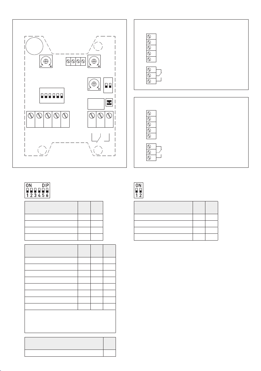
через выход
OUT3
: абсолютная влажность, соотношение компонентов смеси, точка росы и температура по влажному термометру
(переключение с помощью DIP-переключателя).
Датчик используется в медицинской, холодильной, контрольно-измерительной технике, системах кондиционирования,
оборудовании для особо чистых и стерильных помещений. Датчик откалиброван на заводе.
Специалист может выполнить точную настройку в зависимости от условий окружающей среды.
ТЕХНИЧЕСКИЕ ДАННЫЕ
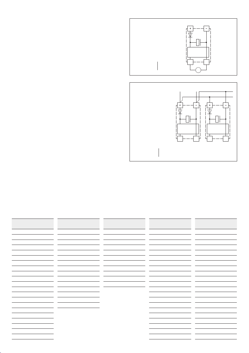
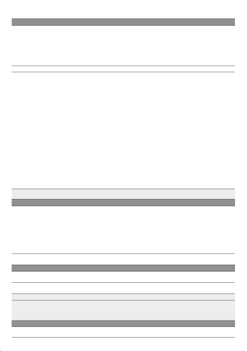
Напряжение питания: 24 Bперем./пост. тока (±10%)
Нагрузка: > 100кОм для варианта U; 100...500Ом для варианта I
Потребляемая мощность: обычно <6Вт при 24В пост. тока, пиковый ток 200мА
Измеряемые величины: относительная влажность [%], температура [°C]
Другие величины: абсолютная влажность [г/м3], соотношение компонентов смеси [г/кг],
точка росы [°C], температура по влажному термометру [°C]
Выходы: 3 активных выхода (0–10В или 4...20мА)
1 переключающий контакт
Чувств. эл.:
цифровой датчик влажности со встроенным датчиком температуры,
малый гистерезис, высокая долговременная стабильность,
с защитой от конденсации благодаря функции нагрева
(дополнительно второй, отдельный чувствительный элемент для измерения температуры)
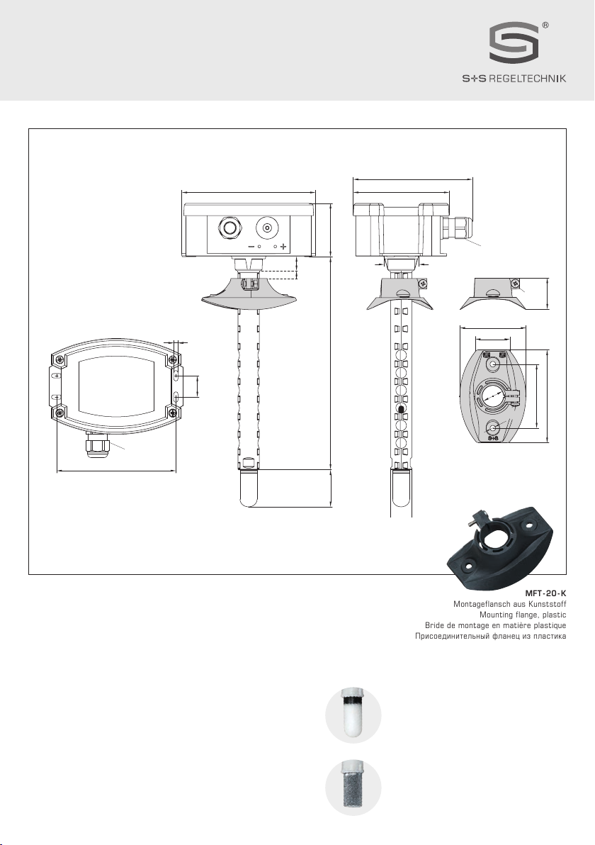
Защита чувств. эл.:
пластиковый
спеченный фильтр, Ø16мм, L= 35мм, сменный
(опционально
металлокерамический
фильтр, Ø16мм, L= 32мм)
ВЛАЖНОСТЬ
Диапазон изм. влажности: 0...100 % отн. вл.
Погреш. (влажность): обычно ± 3,0 %
(30...70 % отн. вл.) при +25 °C, иначе ± 3,5 %
(Отклонение альтернативных величин вытекает из
отклонений значений влажности и температуры.)
Вых. сигнал влажности: 0–10B для варианта U; 4...20мА для варианта I
ТЕМПЕРАТУРА
Диапазон изм. температуры:
переключение между 4 диапазонами
(см. таблицу)
0...+50 °C (default); –20...+50 °C; –20...+80 °C; 0...+100 °C
Погреш. (температура): обычно ±0,5К при +25 °C
Вых. сигнал температуры: 0–10B для варианта U; 4...20мА для варианта I
Долговр. стабильность: ±1% в год
Время сраб. (t90): < 60с
Время выхода на раб. режим: < 10мин
Эл. подключение: 0,14–1,5 мм², с помощью винтовых зажимов
Кабельное соед.:
резьбовой кабельный ввод
из пластика (M16×1,5; с разгрузкой от натяжения,
сменное исполнение, макс. внутренний диаметр 10,4мм)
Корпус: пластик,
устойчивый к ультрафиолетовому излучению,
полиамид, 30% усиление стеклянными шариками,
с быстрозаворачиваемыми винтами(комбинация шлиц ⁄крестовый шлиц),
цвет— транспортный белый (аналогичен RAL9016), крышка дисплея прозрачная!
Размеры корпуса: 126 x 90 x 50 мм (Tyr 2)
Защитная трубка:
PLEUROFORM
TM, полиамид (PA6), с защитой от проворачивания,
Ø20мм, NL= 235мм (опционально 135мм), vmax= 30м/с (воздух)
Монтаж/подключ.: при помощи присоединительного фланца (содержится в комплекте поставки)
Температура окруж. среды: хранение: –20...+50 °C; эксплуатация: –20...+50 °C
Доп. влажность воздуха: < 99 % отн. вл., без конденсата, без вредных веществ
Класс защиты: III (согласно стандарту EN60730)
Степень защиты: корпус
IP 65
(согласно EN 60529), чувствительный элемент IP20
Нормы: соответствие нормам ЕС, электромагнитная совместимость согласно EN61326,
Директиве 2014 ⁄ 30 ⁄ EU «Электромагнитная совместимость»
Продолжение на следующей странице!

19
rHYGRASREG®KFTF-35
Rev. Data - V20
ТЕХНИЧЕСКИЕ ДАННЫЕ (продолжение)
ПРИНЦИП РАБОТЫ
Постоянный нагрев датчика влажности в значительной степени затрудняет или предотвращает
образование на нем конденсата в пределах системных ограничений. Обеспечивается более
быстрая реакция при колебаниях влажности даже в диапазоне выше 95% отн. вл.
Датчик (комбинированный чувствительный элемент для измерения влажности и температуры)
нагревается прибл. на 3К выше температуры окружающей среды. На основе измеренной
влажности при повышенной температуре, температуры микросхемы датчика и температуры
окружающей среды (с помощью второго, отдельного чувствительного элемента для измерения
температуры) определяется фактическая относительная влажность.
ПРИНАДЛЕЖНОСТИ
см. таблицу
Тип ⁄ WG01
Диапазон измерения
влажность температура
Выход
активный
Выход Дисплей
переключающий
Арт. №
KFTF-35 - I Вариант I
KFTF-35-I/W
0
...
100 % отн. вл.
0...20г/м3(a.F.)
0...25г/м3(a.F.)
0...20г/кг (MV)
0...25г/кг (MV)
0...+50°C (TP)
−20...+50°C (TP)
−30...+30°C (
FKT
)
−20...+50°C (FKT)
0
...
+50 °C
–20...+50 °C
–20...+80 °C
0...+100 °C
3x
4...20мА
1x переключающий
контакт
1201-814B-1000-000
KFTF-35-I/W
LCD
(см. выше) (см. выше) 3x
4...20мА
1x переключающий
контакт ■
1201-814B-1200-000
KFTF-35 - U Вариант U
KFTF-35-U/W (см. выше) (см. выше) 3x
0–10B
1x переключающий
контакт
1201-814A-1000-000
KFTF-35-U/W
LCD
(см. выше) (см. выше) 3x
0–10B
1x переключающий
контакт ■
1201-814A-1200-000
Опционально: укороченная защитная трубка
PLEUROFORM
TM L = 100 мм по запросу
Примечание
На основании измеренных значений рассчитываются
альтернативные
величины
,
которые можно считать через выход
OUT3
:
абсолютная влажность, соотношение компонентов смеси, точка росы и температура по влажному термометру
(переключение с помощью DIP-переключателя)
ПРИНАДЛЕЖНОСТИ
SF-M Металлокерамический
фильтр, Ø16мм, L= 32мм, сменный,
из нержавеющей стали
V4A
(1.4 404)
7000-0050-2200-100

20
rHYGRASREG®KFTF-35
Rev. Data - V20
Схема подключения Схема соединения
Схема соединения
KFTF-35 - xx
6
7
8
2
3
4
5
1
NC Normally Closed
NO Normally Open
M Common
+UB 24V AC/DC
Output Humidity 4...20mA
Output Temperature 4...20mA
Output altern. parameters 4...20mA
–UB GND
6
7
8
2
3
4
5
1
NC Normally Closed
NO Normally Open
M Common
+UB 24V AC/DC
Output Humidity 0-10V
Output Temperature 0-10V
Output altern. parameters 0-10V
–UB GND
6 7 8
NC MNO
1 2 3
UB+ GND HUM
4 5
TEMP
thershold
OUT3
123456
ON DIP
12
ON
TEMP
offset
HUM
offset
123456
ON DIP
12
ON
TEMP
offset
HUM
offset
thershold
SET potentiometer
setting switching point
OFFSET potentiometer
HUM = humidity (± 5 %RH)
TEMP = temperature (± 5 K)
LED
(on =
active
)
relay / switching point exceeded
DIP
assignment relay
DIP
multi-range switching temperature
and alternative parameters
Relay
Присваивание
функции реле
DIP
1
DIP
2
неактивно
(default) OFF OFF
Влажность
O N
OFF
Температура OFF
O N
Альтернативные величины
O N O N
Диапазоны измерения
температуры
DIP
1
DIP
2
0
...
+50 °C
(default)OFF OFF
–20...+50 °C
O N
OFF
–20...+80 °C OFF
O N
0...+100 °C
O N O N
Примечание
:обслуживание только на заводе,
при эксплуатации должно быть в положении OFF!
DIP
6
Эксплуатация
(default) OFF
Диапазоны измерения
альтернативных величин
DIP
3
DIP
4
DIP
5
(a.F.)
0
...
20 г ⁄ м3
(default)OFF OFF OFF
(a.F.) 0...25 г/м3
O N
OFF OFF
(MV) 0...20 г/кг OFF
O N
OFF
(MV) 0...25 г/кг
O N O N
OFF
(TP) 0...+50 °C OFF OFF
O N
(TP) –20...+50 °C
O N
OFF
O N
(FKT) –30...+30 °C OFF
O N O N
(FKT) –20...+50 °C
O N O N O N
(a.F.) = абсолютная влажность [г/м³]
(MV) = соотношение компонентов смеси [г/кг]
(TP) = точка росы [°C]
(FKT) = температуры по влажному термометру [°C]
Тип ⁄ WG01
Диапазон измерения
влажность температура
Выход
активный
Выход Дисплей
переключающий
Арт. №
KFTF-35 - I Вариант I
KFTF-35-I/W
0
...
100 % отн. вл.
0...20г/м3(a.F.)
0...25г/м3(a.F.)
0...20г/кг (MV)
0...25г/кг (MV)
0...+50°C (TP)
−20...+50°C (TP)
−30...+30°C (
FKT
)
−20...+50°C (FKT)
0
...
+50 °C
–20...+50 °C
–20...+80 °C
0...+100 °C
3x
4...20мА
1x переключающий
контакт
1201-814B-1000-000
KFTF-35-I/W
LCD
(см. выше) (см. выше) 3x
4...20мА
1x переключающий
контакт ■
1201-814B-1200-000
KFTF-35 - U Вариант U
KFTF-35-U/W (см. выше) (см. выше) 3x
0–10B
1x переключающий
контакт
1201-814A-1000-000
KFTF-35-U/W
LCD
(см. выше) (см. выше) 3x
0–10B
1x переключающий
контакт ■
1201-814A-1200-000
Опционально: укороченная защитная трубка
PLEUROFORM
TM L = 100 мм по запросу
Примечание
На основании измеренных значений рассчитываются
альтернативные
величины
,
которые можно считать через выход
OUT3
:
абсолютная влажность, соотношение компонентов смеси, точка росы и температура по влажному термометру
(переключение с помощью DIP-переключателя)
ПРИНАДЛЕЖНОСТИ
SF-M Металлокерамический
фильтр, Ø16мм, L= 32мм, сменный,
из нержавеющей стали
V4A
(1.4 404)
7000-0050-2200-100
Table of contents
Languages:
Other S+S Regeltechnik Security Sensor manuals

S+S Regeltechnik
S+S Regeltechnik KINASGARD RBWF-UP Repair manual

S+S Regeltechnik
S+S Regeltechnik AERASGARD RLQ-CO2-W Repair manual

S+S Regeltechnik
S+S Regeltechnik RHEASGARD KLGF Series Repair manual

S+S Regeltechnik
S+S Regeltechnik KINASGARD DBWF-LF-FTF Series Repair manual

S+S Regeltechnik
S+S Regeltechnik KINASGARD DBWF Repair manual

S+S Regeltechnik
S+S Regeltechnik AERASGARD APS-SD Repair manual

S+S Regeltechnik
S+S Regeltechnik THERMASREG RTR-B Series Repair manual

S+S Regeltechnik
S+S Regeltechnik HYGRASGARD AFTF-EtherCAT P Repair manual