S+S Regeltechnik THERMASREG RTR-B Series Repair manual

THERMASREG® RTR - B
D G F r
Herzlichen Glückwunsch!
Sie haben ein deutsches Qualitätsprodukt erworben.
Congratulations!
You have bought a German quality product.
Félicitations!
Vous avez fait l’acquisition d’un produit allemand de qualité.
Примите наши поздравления!
Вы приобрели качественный продукт, изготовленный в Германии.
D
Bedienungs- und Montageanleitung
Raumtemperaturregler, mechanisch,
Aufputz
G
Operating Instructions, Mounting & Installation
Room temperature controllers, mechanical,
on-wall
F
Notice d’instruction
Thermostat d’ambiance, mécanique,
en saillie
r
Руководство по монтажу и обслуживанию
Терморегулятор для внутренних помещений, механический,
для открытой установки
RTR - B xx
mit Außeneinstellung
with external setting
avec réglage externe
c органы настройки снаружи
RTR - B 747
mit Inneneinstellung
with internal setting
avec réglage interne
с органами настройки внутри
S+S REGELTECHNIK GMBH
PIRNAER STRASSE 20
90411 NÜRNBERG ⁄GERMANY
FON +49 (0) 911 ⁄ 519 47-0
FAX +49 (0) 911 ⁄ 519 47-70
www.SplusS.de
6000-2310-0000-1XX 23100-2019 V102 04 ⁄ 2019

THERMASREG® RTR - B
D G F r
Maßzeichnung
Gehäuse E 1
(Abb. ähnlich)
Dimensional drawing
Housing E 1
(Picture similar)
Plan coté
boîtier E 1
(Fig. similaire)
Габаритный чертеж
Корпус E 1
(похожое изображ)
Maßzeichnung
Gehäuse E 1
mit Poti (Abb. ähnlich)
Dimensional drawing
Housing E 1
with one potentiometer (Picture similar)
Plan coté
boîtier E 1
avec un seul potentiomètre
(Fig. similaire)
Габаритный чертеж
Корпус E 1
с одним потенциометром (похожое изображ)
TK: ø 60
75
75
25
TK: ø 60
75
75
25

DTHERMASREG®RTR -B
Rev. 2019 - V22
Einstufiger, mechanischer Einzelraumregler, Bi-Metalltechnik,
THERMASREG
®
RTR - B
mit thermischer Rückführung, geeignet zur Temperaturüber-
wachung oder -regelung in trockenen Räumen bzw. zur Ansteuerung von Heizungen aller Art, als Raumthermostat. Bei stromlos offenen Heizkörper-
ventilen ist der Kühlausgang vom Wechsler (Schließer) anzuschließen. An Öffnerkontakte können max. 10 Ventil-Stellantriebe und beim Schließer
max. 5 Ventil-Stellantriebe angeschlossen werden.
TECHNISCHE DATEN
Schaltvermögen: 230 V AC, 50 - 60 Hz
(Kontaktbelastung) Heizen: 10 mA...10 (4) A, DC 30 W
Kühlen: 10 mA...5 (2) A
Fühlerelement: Bimetall
Regelbereich: +5...+30 °C
Ausgänge: Öffner oder Wechsler
Schaltdifferenz: ca. 0,5 K
Gehäuse: Kunststoff, Werkstoff ABS,
Farbe Reinweiß (ähnlich RAL 9010)
Abmaße Gehäuse: 75 x 75 x 25 mm (E1)
elektrischer Anschluss: 0,14 - 2,5 mm2,
über Schraubklemmen
Montage: Wandmontage oder auf UP-Dose, Ø 55 mm,
Unterteil mit 4-Loch, für Befestigung auf
senkrecht oder waagerecht installierten UP-Dosen
für Kabeleinführung hinten, mit Sollbruchstelle
für Kabeleinführung oben ⁄ unten bei AP
Schutzklasse: II (nach EN 60 730)
Schutzart: IP 30 (nach EN 60 529)
Normen: CE-Konformität,
EMV-Richtlinie 2014 ⁄ 30 ⁄ EU,
Niederspannungsrichtlinie 2014 ⁄ 35 ⁄ EU
THERMASREG
®
RTR - B
Raumtemperaturregler
Typ ⁄ WG01 Temperatur-
bereich
Funktion Ausgang Art.-Nr.
RTR - B 121 ⁄ B 124 ⁄ B 721 Außeneinstellung
RTR-B 121 +5...+30 °C Heizen Öffner 1102-4011-2100-000
RTR-B 124 +5...+30 °C Heizen, Temperaturabsenkung - 5 K Öffner 1102-4011-2400-000
RTR-B 721 +5...+30 °C Heizen, Kühlen Wechsler 1102-4017-2100-000
RTR - B 747 Inneneinstellung
RTR-B 747 +5...+30 °C Heizen, Kühlen Wechsler 1102-4017-4700-000

DTHERMASREG®RTR -B
Rev. 2019 - V22
Anschlussbild
RTR - B 124
Anschlussbild
RTR - B 747
24 V
Anschlussbild
RTR - B 121
Anschlussbild
RTR - B 721

DWichtige Hinweise
Als AGB gelten ausschließlich unsere sowie die gültigen „Allgemeinen Lieferbedingungen für Erzeugnisse und Leistungen der Elektroindustrie“
(ZVEI Bedingungen) zuzüglich der Ergänzungsklausel „Erweiterter Eigentumsvorbehalt“.
Außerdem sind folgende Punkte zu beachten:
– Vor der Installation und Inbetriebnahme ist diese Anleitung zu lesen und die alle darin gemachten Hinweise sind zu beachten!
– Der Anschluss der Geräte darf nur an Sicherheitskleinspannung und im spannungslosen Zustand erfolgen. Um Schäden und Fehler am Gerät
(z.B. durch Spannungsinduktion) zu verhindern, sind abgeschirmte Leitungen zu verwenden, eine Parallelverlegung zu stromführenden Leitungen zu
vermeiden und die EMV- Richtlinien zu beachten.
– Dieses Gerät ist nur für den angegebenen Verwendungszweck zu nutzen, dabei sind die entsprechenden Sicherheitsvorschriften des VDE,
der Länder, ihrer Überwachungsorgane, des TÜV und der örtlichen EVU zu beachten.
Der Käufer hat die Einhaltung der Bau- und Sicherungsbestimmung zu gewährleisten und Gefährdungen aller Art zu vermeiden.
– Für Mängel und Schäden, die durch unsachgemäße Verwendung dieses Gerätes entstehen, werden keinerlei Gewährleistungen und Haftungen
übernommen.
– Folgeschäden, welche durch Fehler an diesem Gerät entstehen, sind von der Gewährleistung und Haftung ausgeschlossen.
– Montage und Inbetriebnahme der Geräte darf nur durch Fachpersonal erfolgen.
– Es gelten ausschließlich die technischen Daten und Anschlussbedingungen der zum Gerät gelieferten Montage- und Bedienungsanleitung,
Abweichungen zur Katalogdarstellung sind nicht zusätzlich aufgeführt und im Sinne des technischen Fortschritts und der stetigen Verbesserung
unserer Produkte möglich.
– Bei Veränderungen der Geräte durch den Anwender entfallen alle Gewährleistungsansprüche.
– Dieses Gerät darf nicht in der Nähe von Wärmequellen (z.B. Heizkörpern) oder deren Wärmestrom eingesetzt werden, eine direkte Sonnen-
einstrahlung oder Wärmeeinstrahlung durch ähnliche Quellen (starke Leuchte, Halogenstrahler) ist unbedingt zu vermeiden.
– Der Betrieb in der Nähe von Geräten, welche nicht den EMV- Richtlinien entsprechen, kann zur Beeinflussung der Funktionsweise führen.
– Dieses Gerät darf nicht für Überwachungszwecke, welche dem Schutz von Personen gegen Gefährdung oder Verletzung dienen und
nicht als Not-Aus-Schalter an Anlagen und Maschinen oder vergleichbare sicherheitsrelevante Aufgaben verwendet werden.
– Die Gehäuse- und Gehäusezubehörmaße können geringe Toleranzen zu den Angaben dieser Anleitung aufweisen.
– Veränderungen dieser Unterlagen sind nicht gestattet.
– Reklamationen werden nur vollständig in Originalverpackung angenommen.
Eine Inbetriebnahme ist zwingend durchzuführen und darf nur von Fachpersonal vorgenommen werden!
Vor der Montage und Inbetriebnahme ist diese Anleitung zu lesen und die alle darin gemachten Hinweise sind zu beachten!

GTHERMASREG®RTR -B
Rev. 2019 - V22
THERMASREG
®
RTR - B
Room temperature controllers
Type ⁄ WG01 Temperature
Range
Function Output Item No.
RTR - B 121 ⁄ B 124 ⁄ B 721 External setting
RTR-B 121 +5...+30 °C Heating Breaker 1102-4011-2100-000
RTR-B 124 +5...+30 °C Heating, temperature reduction - 5 K Breaker 1102-4011-2400-000
RTR-B 721 +5...+30 °C Heating, cooling Changeover contact 1102-4017-2100-000
RTR - B 747 Internal setting
RTR-B 747 +5...+30 °C Heating, cooling Changeover contact 1102-4017-4700-000
One-step mechanical single room controller
THERMASREG
®
RTR - B
in bi-metal technology with thermal feedback for monitoring or controlling
temperatures in dry rooms, or for activating any kind of heating system as room thermostat. For currentless open radiator valves, the cooling output
from the changeover contact (normally open contact) must be connected. At breaker contacts, a maximum
of 10 valve actuators can be connected
and at normally open contacts a maximum of 5 valve actuators.
TECHNICAL DATA
Switching capacity: 230 V AC, 50 - 60 Hz
(Contact load) heating: 10mA…10 (4) A, DC 30 W
cooling: 10 mA…5 (2) A
Sensor element: bi-metal
Control range: +5...+30°C
Output: breaker or changeover contact
Operating difference: approx. 0.5 K
Housing: plastic, material ABS,
colour pure white (similar to RAL 9010)
Dimensions: 75 x 75 x 25mm (E1)
Electrical connection: 0.14 - 2.5 mm2
via terminal screws
Installation: wall mounting or on in-wall flush box Ø 55 mm,
base with 4-hole for mounting on vertically or
horizontally installed in-wall flush boxes for cable
entry from the back, with predetermined breaking
point for on-wall cable entry from top ⁄ bottom
in case of plain on-wall installation
Protection class: II (according to EN 60 730)
Protection type: IP 30 (according to EN 60 529)
Standards: CE conformity,
EMC directive 2014 ⁄ 30 ⁄ EU,
low-voltage directive 2014 ⁄ 35 ⁄ EU

GTHERMASREG®RTR -B
Rev. 2019 - V22
Connecting diagram
RTR - B 124
Connecting diagram
RTR - B 747
24 V
Connecting diagram
RTR - B 121
Connecting diagram
RTR - B 721

GGeneral notes
Our “General Terms and Conditions for Business“ together with the “General Conditions for the Supply of Products and Services of the Electrical and
Electronics Industry“ (ZVEI conditions) including supplementary clause “Extended Retention of Title“ apply as the exclusive terms and conditions.
In additionIn addition, the following points are to be observed:
– These instructions must be read before installation and putting in operation and all notes provided therein are to be regarded!
– Devices must only be connected to safety extra-low voltage and under dead-voltage condition. To avoid damages and errors the device
(e.g. by voltage induction) shielded cables are to be used, laying parallel with current-carrying lines is to be avoided, and EMC directives are to be
observed.
– This device shall only be used for its intended purpose. Respective safety regulations issued by the VDE, the states, their control authorities, the
TÜV and the local energy supply company must be observed. The purchaser has to adhere to the building and safety regulations and has to prevent
perils of any kind.
– No warranties or liabilities will be assumed for defects and damages arising from improper use of this device.
– Consequential damages caused by a fault in this device are excluded from warranty or liability.
– These devices must be installed and commissioned by authorised specialists.
– The technical data and connecting conditions of the mounting and operating instructions delivered together with the device are exclusively valid.
Deviations from the catalogue representation are not explicitly mentioned and are possible in terms of technical progress and continuous
improvement of our products.
– In case of any modifications made by the user, all warranty claims are forfeited.
– This device must not be installed close to heat sources (e.g. radiators) or be exposed to their heat flow. Direct sun irradiation or heat irradiation
by similar sources (powerful lamps, halogen spotlights) must absolutely be avoided.
– Operating this device close to other devices that do not comply with EMC directives may influence functionality.
– This device must not be used for monitoring applications, which serve the purpose of protecting persons against hazards or injury,
or as an EMERGENCY STOP switch for systems or machinery, or for any other similar safety-relevant purposes.
– Dimensions of housing or housing accessories may show slight tolerances on the specifications provided in these instructions.
– Modifications of these records are not permitted.
– In case of a complaint, only complete devices returned in original packing will be accepted.
Commissioning is mandatory and may only be performed by qualified personnel!
These instructions must be read before installation and commissioning and all notes provided therein are to be regard

FTHERMASREG®RTR -B
Rev. 2019 - V22
Le thermostat d’ambiance
THERMASREG
®
RTR - B
, régulateur individuel par pièce mécanique à un étage, technique du bimétal, avec optimisation
thermique, est conçu pour la surveillance ou la régulation de température dans des locaux secs ou le pilotage de chauffages de toutes sortes, comme
thermostat d'ambiance. Pour les vannes de radiateur ouvertes hors tension, il faut raccorder la sortie refroidissement de l’inverseur (contact NO). Il
est possible de raccorder jusqu’à 10 servomoteurs pour vannes aux contacts NF et jusqu’à 5 servomoteurs pour vannes au contact NO.
CARACTÉRISTIQUES TECHNIQUES
Pouvoir de coupure : 230 V ca, 50 - 60 Hz
(charge de contact) chauffer : 10 mA...10 (4) A, cc 30 W
refroidir : 10mA...5 (2) A
Élément de sonde : bimétal
Plage de réglage : +5...+30 °C
Sorties : contact NF ou inverseur
Différentiel (hystérésis) : environ 0,5 K
Boîtier : matière plastique, matériau ABS,
couleur blanc pur (similaire à RAL 9010)
Dimensions : 75 x 75 x 25 mm (E1)
Raccordement électrique : 0,14 - 2,5 mm2,
par bornes à vis
Montage : montage mural ou sur boîte d’encastrement, Ø 55 mm,
partie inférieure avec 4 trous, pour fixation sur boîtes
d’encastrement montées verticalement ou horizontalement
pour passage de câble par l’arrière, avec point de rupture
pour passage de câble par le haut ⁄ bas pour montage en saillie
Classe de protection : II (selon EN 60 730)
Indice de protection : IP 30 (selon EN 60 529)
Normes : conformité CE,
Directive « CEM » 2014 ⁄ 30 ⁄ EU,
Directive basse tension 2014 ⁄ 35 ⁄ EU
THERMASREG
®
RTR - B
Thermostat d’ambiance
Type ⁄ WG01 plage de
température
fonctionnement sortie référence
RTR - B 121 ⁄ B 124 ⁄ B 721 réglage externe
RTR-B 121 +5...+30 °C chauffer contact NF 1102-4011-2100-000
RTR-B 124 +5...+30 °C chauffer, abaissement de température - 5 K contact NF 1102-4011-2400-000
RTR-B 721 +5...+30 °C chauffer, refroidir inverseur 1102-4017-2100-000
RTR - B 747 réglage interne
RTR-B 747 +5...+30 °C chauffer, refroidir inverseur 1102-4017-4700-000

FTHERMASREG®RTR -B
Rev. 2019 - V22
Schéma de raccordement
RTR - B 124
Schéma de raccordement
RTR - B 747
24 V
Schéma de raccordement
RTR - B 121
Schéma de raccordement
RTR - B 721

FGénéralités
Seules les CGV de la société S+S, les « Conditions générales de livraison du ZVEI pour produits et prestations de l’industrie électronique» ainsi que
la clause complémentaire « Réserve de propriété étendue » s’appliquent à toutes les relations commerciales entre la société S+S et ses clients.
Il convient en outre de respecter les points suivants :
– Avant de procéder à toute installation et à la mise en service, veuillez lire attentivement la présente notice et toutes les consignes qui y sont
précisées !
– Les raccordements électriques doivent être exécutés HORS TENSION. Ne branchez l’appareil que sur un réseau de très basse tension de sécurité.
Pour éviter des endommagements ⁄ erreurs sur l’appareil (par ex. dus à une induction de tension parasite), il est conseillé d’utiliser des câbles
blindés, ne pas poser les câbles de sondes en parallèle avec des câbles de puissance, les directives CEM sont à respecter.
– Cet appareil ne doit être utilisé que pour l’usage qui est indiqué en respectant les règles de sécurité correspondantes de la VDE, des Länders,
de leurs organes de surveillance, du TÜV et des entreprises d’approvisionnement en énergie locales. L’acheteur doit respecter les dispositions
relatives à la construction et à la sécurité et doit éviter toutes sortes de risques.
– Nous déclinons toute responsabilité ou garantie pour les défauts et dommages résultant d’une utilisation inappropriée de cet appareil.
– Nous déclinons toute responsabilité ou garantie au titre de tout dommage consécutif provoqué par des erreurs commises sur cet appareil.
– L'installation et la mise en service des appareils doit être effectuée uniquement par du personnel qualifié
– Seules les données techniques et les conditions de raccordement indiquées sur la notice d’instruction accompagnant l’appareil sont applicables,
des différences par rapport à la présentation dans le catalogue ne sont pas mentionnées explicitement et sont possibles suite au progrès
technique et à l’amélioration continue de nos produits.
– En cas de modifications des appareils par l’utilisateur, tous droits de garantie ne seront pas reconnus.
– Cet appareil ne doit pas être utilisé à proximité des sources de chaleur (par ex. radiateurs) ou de leurs flux de chaleur, il faut impérativement
éviter
un ensoleillement direct ou un rayonnement thermique provenant de sources similaires (lampes très puissantes, projecteurs à halogène).
– L’utilisation de l’appareil à proximité d’appareils qui ne sont pas conformes aux directives « CEM» pourra nuire à son mode de fonctionnement.
– Cet appareil ne devra pas être utilisé à des fins de surveillance qui visent à la protection des personnes contre les dangers ou les blessures ni
comme interrupteur d’arrêt d’urgence sur des installations ou des machines ni pour des fonctions relatives à la sécurité comparables.
– Il est possible que les dimensions du boîtier et des accessoires du boîtier divergent légèrement des indications données dans cette notice.
– Il est interdit de modifier la présente documentation.
– En cas de réclamation, les appareils ne sont repris que dans leur emballage d’origine et si tous les éléments de l’appareil sont complets.
La mise en service ne doit être effectuée que par du personnel qualifié! Avant de procéder à l'installation et à la mise en
service, veuillez lire attentivement la présente notice et toutes les consignes qui y sont précisées !

rTHERMASREG®RTR -B
Rev. 2019 - V22
THERMASREG
®
RTR - B
Терморегулятор для внутренних помещений
Тип ⁄ WG01 Диапазон
температур
Принцип
работы
Выход Арт. №
RTR - B 121 ⁄ B 124 ⁄ B 721 органы настройки снаружи
RTR-B 121 +5...+30 °C нагрев размыкающий выход 1102-4011-2100-000
RTR-B 124 +5...+30 °C нагрев, понижение температуры -5K размыкающий выход 1102-4011-2400-000
RTR-B 721 +5...+30 °C нагрев, охлаждение переключающий 1102-4017-2100-000
RTR - B 747 органы настройки внутри
RTR-B 747 +5...+30 °C нагрев, охлаждение переключающий 1102-4017-4700-000
Одноступенчатый механический регулятор для отдельных помещений, биметаллический,
THERMASREG
®
RTR - B
, с обратной связью по темпе-
ратуре, может применяться в качестве термостата для контроля или регулирования температуры в сухих помещениях, а также для управления
отопительным оборудованием любого типа. В случае применения открытых в обесточенном состоянии радиаторных клапанов следует подключать
выход охлаждения замыкающего (переключающего) контакта. К размыкающим контактам возможно подключение до 10 сервоприводов клапанов,
а к замыкающему контакту— до 5.
ТЕХНИЧЕСКИЕ ДАННЫЕ
Коммутационная способность: 230B переменного тока, 50–60 Гц
(контактная нагрузка) нагрев: 10мА…10 (4) A, постоянный ток, 30 Вт
охлаждение: 10 мА…5 (2) A
Чувствительный элемент: биметаллический
Диапазон регулирования: +5...+30°C
Выходы: размыкающий или переключающий
Разность между температурами
включения и выключения: прибл.0,5K
Корпус: пластик, акрилонитрил-бутадиенстирол (ABS),
цвет— чистый белый (аналогичен RAL9010)
Размеры: 75 x 75 x 25 мм (E1)
Электрическое подключение: 0,14–2,5мм², по винтовым зажимам
Монтаж: настенный или на монтажную коробку Ø 55 мм,
низ с четырьмя отверстиями, для закрепления на
вертикально или горизонтально установленных коробках,
с шаблоном отверстия под открытый ввод кабеля
Класс защиты: II (согласно EN 60730)
Степень защиты: IP 30 (согласно EN 60 529)
Нормы: соответствие CE-нормам,
директива 2014 ⁄ 30 ⁄ EU «Электромагнитная совместимость»,
директива 2014 ⁄ 35 ⁄ EU «Низковольтное оборудование»

rTHERMASREG®RTR -B
Rev. 2019 - V22
Схема соединения
RTR - B 124
Схема соединения
RTR - B 747
24 V
Схема соединения
RTR - B 121
Схема соединения
RTR - B 721

rУказания к продуктам
В качестве Общих Коммерческих Условий имеют силу исключительно наши Условия, а также действительные «Общие условия поставки продукции
и услуг для электрической промышленности» (ZVEI) включая дополнительную статью «Расширенное сохранение прав собственности».
Помимо этого, следует учитывать следующие положения:
– Перед установкой и вводом в эксплуатацию следует прочитать данное руководство; должны быть учтены все приведенные в нем указания!
– Подключение прибора должно осуществляться исключительно к безопасно малому напряжению и в обесточенном состоянии.
Во избежание повреждений и отказов (например, вследствие наводок) следует использовать экранированную проводку,
избегать параллельной прокладки токоведущих линий и учитывать предписания по электромагнитной совместимости.
– Данный прибор следует применять только по прямому назначению, учитывая при этом соответствующие предписания VDE
(союза немецких электротехников), требования, действующие в Вашей стране, инструкции органов технического надзора и местных
органов энергоснабжения. Надлежит придерживаться требований строительных норм и правил, а также техники безопасности и
избегать угроз безопасности любого рода.
– Мы не несем ответственности за ущерб и повреждения, возникающие вследствие неправильного применения наших устройств.
– Ущерб, возникший вследствие неправильной работы прибора, не подлежит устранению по гарантии.
– Монтаж и ввод в эксплуатацию должны осуществляться только специалистами.
– Действительны исключительно технические данные и условия подключения, приведенные в поставляемых с приборами руководствах по
монтажу и эксплуатации. Отклонения от представленных в каталоге характеристик дополнительно не указываются, несмотря на их возможность в
силу технического прогресса и постоянного совершенствования нашей продукции.
– В случае модификации приборов потребителем гарантийные обязательства теряют силу.
– Не разрешается использование прибора в непосредственной близости от источников тепла (например, радиаторов отопления)
или создаваемых ими тепловых потоков; следует в обязательном порядке избегать попадания прямых солнечных лучей или теплового излучения от
аналогичных источников (мощные осветительные приборы, галогенные излучатели).
– Эксплуатация вблизи оборудования, не соответствующего нормам электромагнитной совместимости (EMV), может влиять на работу приборов.
– Недопустимо использование данного прибора в качестве устройства контроля ⁄ наблюдения, служащего для защиты людей от травм
и угрозы для здоровья ⁄ жизни, а также в качестве аварийного выключателя устройств и машин или для аналогичных задач обеспечения
безопасности.
– Размеры корпусов и корпусных принадлежностей могут в определённых пределах отличаться от указанных в данном руководстве.
– Изменение документации не допускается.
– В случае рекламаций принимаются исключительно цельные приборы в оригинальной упаковке.
Ввод в эксплуатацию обязателен и выполняется только специалистами! Перед монтажом и вводом в эксплуатацию прочитать
данное руководство; должны быть учтены все приведенные в нем указания!

THERMASREG® RTR - B
D G F r
Zum Öffnen des Gehäuses einen Schraubendreher (2,0) in die Nut
mittig ansetzen, nach unten drücken und den Bodenrahmen etwas
anheben. Den Deckel nach vorne ziehen und halten.
To open the enclosure, set a screwdriver (2.0) in the groove at
centre, press down, and lift up the bottom frame slightly. Pull top
cover forward and hold it.
Pour ouvrir le boîtier placer le tournevis (2,0) au centre de l’encoche,
pousser vers le bas et soulever légèrement le cadre inférieur. Tirer
le couvercle vers l’avant et le maintenir.
Чтобы открыть корпус, вставьте жало отвертки (2,0) в паз
по центру, надавите вниз и слегка приподнимите основание
корпуса. Крышку сдвигайте вперед, аккуратно удерживая ее.
Gehäuse
E 1
(Abb. ähnlich)
Housing
Boîtier
Корпус
Irrtümer und technische Änderungen vorbehalten. Alle Angaben entsprechen unserem Kenntnisstand bei Veröffentlichung. Sie dienen nur zur Information über
unsere Produkte und deren Anwendungsmöglichkeiten, bieten jedoch keine Gewähr für bestimmte Produkteigenschaften. Da die Geräte unter verschiedensten
Bedingungen und Belastungen eingesetzt werden, die sich unserer Kontrolle entziehen, muss ihre spezifische Eignung vom jeweiligen Käufer bzw. Anwender selbst
geprüft werden. Bestehende Schutzrechte sind zu berücksichtigen. Einwandfreie Qualität gewährleisten wir im Rahmen unserer Allgemeinen Lieferbedingungen.
Subject to errors and technical changes. All statements and data herein represent our best knowledge at date of publication. They are only meant to inform about
our products and their application potential, but do not imply any warranty as to certain product characteristics. Since the devices are used under a wide range
of different conditions and loads beyond our control, their particular suitability must be verified by each customer and/or end user themselves. Existing property
rights must be observed. We warrant the faultless quality of our products as stated in our General Terms and Conditions.
Sous réserve d'erreurs et de modifications techniques. Toutes les informations correspondent à l'état de nos connaissances au moment de la publication. Elles
servent uniquement à informer sur nos produits et leurs possibilités d'application, mais n'offrent aucune garantie pour certaines caractéristiques du produit. Etant
donné que les appareils sont soumis à des conditions et des sollicitations diverses qui sont hors de notre contrôle, leur adéquation spécifique doit être vérifiée
par l'acheteur ou l'utilisateur respectif. Tenir compte des droits de propriété existants. Nous garantissons une qualité parfaite dans le cadre de nos conditions
générales de livraison.
Возможны ошибки и технические изменения. Все данные соответствуют нашему уровню знаний на момент издания. Они представляют собой информацию о
наших изделиях и их возможностях применения, однако они не гарантируют наличие определенных характеристик. Поскольку устройства используются при
самых различных условиях и нагрузках, которые мы не можем контролировать, покупатель или пользователь должен сам проверить их пригодность. Соблюдать
действующие права на промышленную собственность. Мы гарантируем безупречное качество в рамках наших «Общих условий поставки».
©
Copyright by S+S Regeltechnik GmbH
Nachdruck, auch auszugsweise, nur mit Genehmigung der S+S Regeltechnik GmbH.
Reprint in full or in parts requires permission from S+S Regeltechnik GmbH.
La reproduction des textes même partielle est uniquement autorisée après accord de la société S+S Regeltechnik GmbH.
Перепечатка, в том числе в сокращенном виде, разрешается лишь с согласия S+S Regeltechnik GmbH.

THERMASREG® RTR - B
D G F r
This manual suits for next models
3
Table of contents
Languages:
Other S+S Regeltechnik Security Sensor manuals
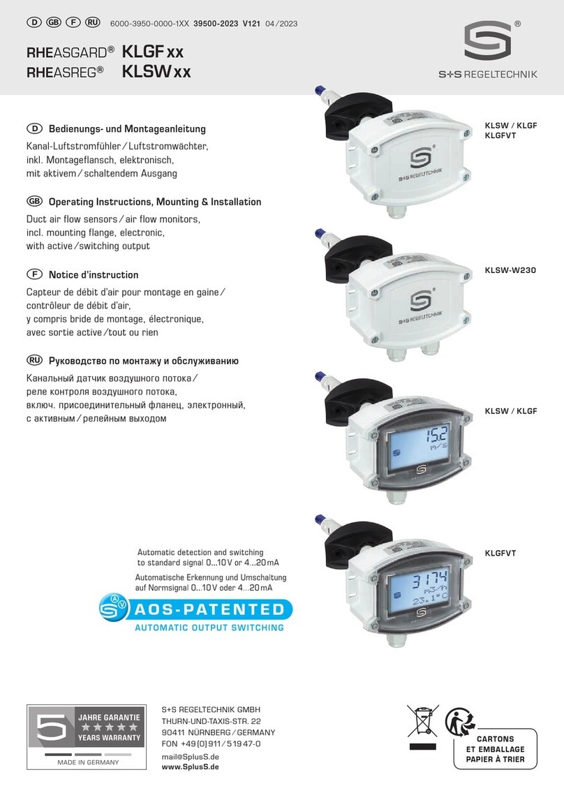
S+S Regeltechnik
S+S Regeltechnik RHEASGARD KLGF Series Repair manual
S+S Regeltechnik
S+S Regeltechnik HYGRASGARD AFTF-EtherCAT P Repair manual
S+S Regeltechnik
S+S Regeltechnik HYGRASREG KFTF-35 Repair manual
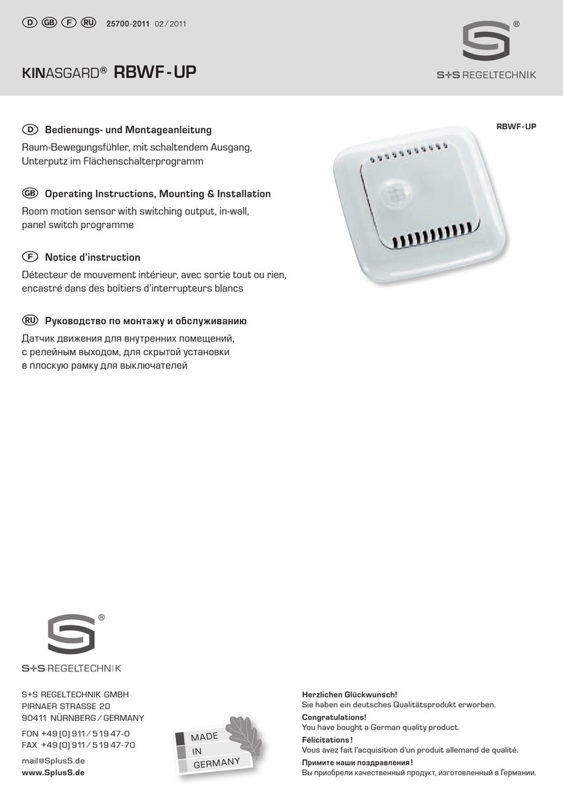
S+S Regeltechnik
S+S Regeltechnik KINASGARD RBWF-UP Repair manual
S+S Regeltechnik
S+S Regeltechnik AERASGARD RLQ-CO2-W Repair manual
S+S Regeltechnik
S+S Regeltechnik KINASGARD DBWF Repair manual
S+S Regeltechnik
S+S Regeltechnik AERASGARD APS-SD Repair manual
S+S Regeltechnik
S+S Regeltechnik KINASGARD DBWF-LF-FTF Series Repair manual
