Vanderbilt bright blue User manual

VANDERBILT INDUSTRIES
bright blue®Manual

VBBIM09/33/20 v5.0.3
i
© 2020 Vanderbilt Industries
This documentation and the software/hardware described herein, is furnished under license and may be used only
in accordance with the terms of such license. Information contained in this manual is subject to change without
notice and does not represent any commitment on the part of Vanderbilt Industries. Vanderbilt Industries assumes
no responsibility or liability for any errors or inaccuracies that may appear in this documentation.
CONTACT INFORMATION
Vanderbilt Industries
Phone: 855-316-3900
Fax: 973-316-3999
www.vanderbiltindustries.com
Vanderbilt Industries Copyright Notice

ii Contents
Contents
Vanderbilt Industries Copyright Notice i
UL Listing Summary 12
Compatible UL evaluated equipment .................................................................................................................12
Hardware Not UL Evaluated...............................................................................................................................12
Firmware Designation........................................................................................................................................13
UL Evaluated Firmware......................................................................................................................................13
The following should be incorporated into the system:.......................................................................................13
Operation Testing and Maintenance..................................................................................................................14
Operation Testing ...................................................................................................................................14
Maintenance ...........................................................................................................................................14
Declaration of Conformity 15
Preface 16
Who should use this book..................................................................................................................................16
How this book is organized ................................................................................................................................16
Symbols and conventions ..................................................................................................................................17
U.S./International Technical Support..................................................................................................................17
Hours of Technical Support ....................................................................................................................17
Before Installation 18
Requirements.....................................................................................................................................................18
Electrical Wiring Considerations.........................................................................................................................18
Before Powering System....................................................................................................................................18
Environmental Consideration.............................................................................................................................19
Cable Requirement Chart ..................................................................................................................................19
Web Browser Requirements ..............................................................................................................................20
Internet Explorer 11 ................................................................................................................................20
Firefox v80.0...........................................................................................................................................20
Apple Safari v13.1 (OS X).......................................................................................................................20
Apple Safari Mobile.................................................................................................................................20

VBBIM09/33/20 v5.0.3
Contents iii
Google Chrome v85.0.............................................................................................................................20
Device Power Requirements..............................................................................................................................21
bright blue 22
Overview............................................................................................................................................................22
Highlights................................................................................................................................................23
Dimensions.............................................................................................................................................23
Power Supply Requirements ..................................................................................................................23
Power method 1 - Single Power Supply..................................................................................................24
Power method 2 - Multiple Power Supplies ............................................................................................24
Configuration Guidelines.........................................................................................................................24
Installation and Configuration Steps .......................................................................................................24
Enclosure Installation.........................................................................................................................................25
Features..................................................................................................................................................25
bright blue Pin Layout ........................................................................................................................................26
bright blue Pin Functions ........................................................................................................................26
Functions On AP02 Controller ................................................................................................................29
bright blue LED Indicators..................................................................................................................................30
bright blue IP Configuration................................................................................................................................30
Static IP Configuration (Recommended).................................................................................................30
DHCP Configuration ...............................................................................................................................37
bright blue Date and Time Setup........................................................................................................................39
Using the bright blue software to set date and time................................................................................39
Using the Discovery and Configuration Tool to set date and time...........................................................43
Battery Replacement..........................................................................................................................................46
VBB-RI 47
Overview............................................................................................................................................................47
Highlights................................................................................................................................................48
Features..................................................................................................................................................48
Specifications..........................................................................................................................................48
VBB-RI Enclosure..............................................................................................................................................49
Features..................................................................................................................................................49
Environmental conditions........................................................................................................................50
Mounting the enclosure...........................................................................................................................50
VBB-RI Pin Layout.............................................................................................................................................50
VBB-RI Pin Functions.............................................................................................................................51

iv Contents
Pins Left at Default..................................................................................................................................51
Pins Not Used.........................................................................................................................................52
Connecting to bright blue ...................................................................................................................................52
Optional - Powering VBB-RI Directly From a Power Supply...................................................................53
Addressing the VBB-RI...........................................................................................................................53
Connecting to Read Head..................................................................................................................................54
Recommended Wire Chart: VBB-RI to Reader Head ............................................................................54
P3 - VBB-RI Pin Connections .................................................................................................................55
XCEED ID XF 1050 Proximity Reader....................................................................................................55
Magnetic Stripe Reader..........................................................................................................................56
Installing Diode for Lock Wiring - Relay .............................................................................................................56
VBB-OBRI 57
Overview............................................................................................................................................................57
Highlights................................................................................................................................................58
Features..................................................................................................................................................58
Specifications..........................................................................................................................................58
PIN Layout .........................................................................................................................................................59
PIN Functions .........................................................................................................................................59
Reader and I/O Assignment....................................................................................................................61
Connecting to bright blue ...................................................................................................................................62
Addressing..............................................................................................................................................62
Connecting to Read Heads................................................................................................................................62
Recommended Wire Chart .....................................................................................................................62
PIN Connections.....................................................................................................................................62
Proximity Reader ....................................................................................................................................63
Magnetic Stripe Reader..........................................................................................................................63
SBB-RI (Legacy) 64
Overview............................................................................................................................................................64
Highlights................................................................................................................................................65
Standard Features..................................................................................................................................65
Specifications..........................................................................................................................................65
SBB-RI Enclosure..............................................................................................................................................65
Features..................................................................................................................................................65
Environmental conditions........................................................................................................................66
Mounting.................................................................................................................................................66

VBBIM09/33/20 v5.0.3
Contents v
SBB-RI Pin Layout.............................................................................................................................................66
SBB-RI Pin Functions.............................................................................................................................67
Connecting to bright blue ...................................................................................................................................68
Optional - Powering SBB-RI Directly From a Power Supply...................................................................69
Addressing the SBB-RI...........................................................................................................................69
Connecting to Read Head..................................................................................................................................70
Recommended Wire Chart: SBB-RI to Reader Head ............................................................................70
P3 - SBB-RI pin connections ..................................................................................................................71
XCEED ID XF 1050 Proximity Reader....................................................................................................71
Magnetic Stripe Reader..........................................................................................................................72
VBB-NRI 73
Overview............................................................................................................................................................73
Highlights................................................................................................................................................74
Standard Features..................................................................................................................................74
Specifications..........................................................................................................................................74
VBB-NRI Enclosure............................................................................................................................................74
Features..................................................................................................................................................74
Environmental conditions........................................................................................................................75
Mounting.................................................................................................................................................75
VBB-NRI IP Configuration..................................................................................................................................75
Static IP Configuration (Recommended).................................................................................................75
DHCP Configuration ...............................................................................................................................80
Configuration GUI (Graphic User Interface)............................................................................................82
VBB-NRI Pin Layout...........................................................................................................................................84
VBB-NRI Pin Functions...........................................................................................................................85
Pins Left at Default..................................................................................................................................86
Pins Not Used.........................................................................................................................................86
Connecting to bright blue ...................................................................................................................................87
Connecting to Read Head..................................................................................................................................88
Recommended Wire Chart: VBB-NRI to Reader Head..........................................................................88
P2 - VBB-NRI pin connections................................................................................................................88
Proximity Reader ....................................................................................................................................89
Magnetic Stripe Reader..........................................................................................................................89
Installing Diode for Lock Wiring - Relay .............................................................................................................90
Upgrading Firmware...........................................................................................................................................90
Verifying Upgrade/Checking Version Number ........................................................................................91

vi Contents
VBB-NRI G2 93
Overview............................................................................................................................................................93
Highlights................................................................................................................................................94
Standard Features..................................................................................................................................94
Specifications..........................................................................................................................................94
VBB-NRI G2 Enclosure......................................................................................................................................94
Features..................................................................................................................................................94
Environmental conditions........................................................................................................................95
Mounting.................................................................................................................................................95
VBB-NRI G2 IP Configuration............................................................................................................................95
Static IP Configuration (Recommended).................................................................................................95
DHCP Configuration ...............................................................................................................................99
Configuration GUI (Graphic User Interface)..........................................................................................102
VBB-NRI G2 Pin Layout...................................................................................................................................105
VBB-NRI G2 Pin Functions...................................................................................................................105
Factory Reset and Power down.......................................................................................................................107
Reboot..................................................................................................................................................107
Power Down .........................................................................................................................................107
Reboot and Reset to Default IP Address..............................................................................................107
Power Down and Reset to Default IP Address .....................................................................................107
Connecting to bright blue .................................................................................................................................108
Connecting to Read Head................................................................................................................................109
Recommended Wire Chart: VBB-NRI G2 to Reader Head..................................................................109
7 & 9 VBB-NRI G2 PIN Connections.................................................................................................109
Proximity Reader ..................................................................................................................................110
Magnetic Stripe Reader........................................................................................................................110
Installing Diode for Lock Wiring - Relay ...........................................................................................................111
Upgrading Firmware.........................................................................................................................................111
Verifying Upgrade/Checking Version Number ......................................................................................112
VRI-1 113
Overview..........................................................................................................................................................113
Highlights..............................................................................................................................................113
Features................................................................................................................................................114
Specifications........................................................................................................................................114
Enclosure.........................................................................................................................................................114
Features................................................................................................................................................114

VBBIM09/33/20 v5.0.3
Contents vii
Environmental conditions......................................................................................................................115
Mounting the enclosure.........................................................................................................................115
PIN Layout .......................................................................................................................................................115
Configuration....................................................................................................................................................115
PIN Functions...................................................................................................................................................116
TB2 –Power source and contact inputs ...............................................................................................116
J2 –Reader Interface Addressing.........................................................................................................116
J3 –On Board Tamper Connection ......................................................................................................116
J4 –RS485 Communication Line Terminator .......................................................................................116
D1 (A) / D2 (B) –Status LEDs ..............................................................................................................117
Connecting to bright blue .................................................................................................................................117
Optional - Powering VRI-1 Directly From a Power Supply....................................................................118
Addressing............................................................................................................................................119
Connecting to Read Head................................................................................................................................120
Recommended Wire Chart: VRI-1 to Reader Head.............................................................................120
TB4 –Reader Head Connections.........................................................................................................121
XCEED ID XF 1050 Proximity Reader..................................................................................................121
Magnetic Stripe Reader........................................................................................................................121
Installing Diode for Lock Wiring - Relay ...........................................................................................................122
VRI-1S3 123
Overview..........................................................................................................................................................123
Highlights..............................................................................................................................................123
Features................................................................................................................................................124
Specifications........................................................................................................................................124
Enclosure.........................................................................................................................................................124
Features................................................................................................................................................124
Environmental conditions......................................................................................................................125
Mounting the enclosure.........................................................................................................................125
PIN Layout .......................................................................................................................................................125
Configuration....................................................................................................................................................125
PIN Functions...................................................................................................................................................126
TB2 –Power source and contact inputs ...............................................................................................126
J2 –Reader Interface Addressing.........................................................................................................126
J3 –On Board Tamper Connection ......................................................................................................126
J4 –RS485 Communication Line Terminator .......................................................................................126
D1 (A) / D2 (B) –Status LEDs ..............................................................................................................127

viii Contents
Connecting to bright blue .................................................................................................................................127
Optional - Powering Directly From a Power Supply..............................................................................128
Addressing............................................................................................................................................129
Connecting to Read Head................................................................................................................................130
Recommended Wire Chart: VRI-1S3 to Reader Head.........................................................................130
TB4 –Reader Head Connections.........................................................................................................130
XCEED ID XF 1050 Proximity Reader..................................................................................................131
Magnetic Stripe Reader........................................................................................................................131
Installing Diode for Lock Wiring - Relay ...........................................................................................................132
VRI-2 / VRI-2S3 133
Overview..........................................................................................................................................................133
Highlights..............................................................................................................................................133
Features................................................................................................................................................134
Specifications........................................................................................................................................134
Enclosure.........................................................................................................................................................134
Features................................................................................................................................................134
Environmental conditions......................................................................................................................135
Mounting the enclosure.........................................................................................................................135
PIN Layout .......................................................................................................................................................135
Configuration....................................................................................................................................................136
PIN Functions...................................................................................................................................................136
TB7 - Power source..............................................................................................................................136
TB6 - Communications .........................................................................................................................137
TB1 –TB5 Contact inputs.....................................................................................................................137
TB10 –TB12 Relay Outputs.................................................................................................................138
J15 –Read head voltage selector.........................................................................................................138
S1 –Addressing.....................................................................................................................................139
A –R2 Status LEDs..............................................................................................................................139
Schlage Adaptable AD-300 Series Locks 141
Overview..........................................................................................................................................................141
Features................................................................................................................................................141
Specifications........................................................................................................................................141
Contacts and Pin Functions..................................................................................................................142
Connecting to bright blue .................................................................................................................................142
Addressing the AD-300 Lock............................................................................................................................143
To address the AD-300 lock: ................................................................................................................143

VBBIM09/33/20 v5.0.3
Contents ix
Schlage VIP Locks 145
Overview..........................................................................................................................................................145
Features................................................................................................................................................145
Specifications........................................................................................................................................145
Contacts, Relays, and Pin Functions....................................................................................................146
Connecting to bright blue .................................................................................................................................147
Addressing the VIP Lock.......................................................................................................................148
Schlage Adaptable AD-400 Series 149
Overview..........................................................................................................................................................149
Schlage AD-400 Components..........................................................................................................................150
Schlage AD-400 Series Wireless modules.......................................................................................................150
Panel Interface Module (PIM400-485-VBB)..........................................................................................150
AD-400 Series Wireless Locks .............................................................................................................151
WRI400.................................................................................................................................................153
Wiring Instructions............................................................................................................................................154
Wiring between bright blue and PIM400...............................................................................................154
PIM400 Configuration ......................................................................................................................................155
Log In to SUS .......................................................................................................................................155
Pair to PDA...........................................................................................................................................155
Set PIM400 Address.............................................................................................................................156
AD-400 Series Lock Configuration...................................................................................................................159
Linking/Addressing................................................................................................................................159
Diagnostics ...........................................................................................................................................160
WRI400 Configuration......................................................................................................................................162
Connecting to HHD/Coupling/Linking....................................................................................................162
Additional Configuration........................................................................................................................164
Schlage NDE Series Wireless Locks with ENGAGE 168
Overview..........................................................................................................................................................168
Schlage NDE Series Components...................................................................................................................169
Schlage NDE Series Wireless Modules ...........................................................................................................169
Gateway (GWE - ENGAGE) .................................................................................................................169
NDE Series Wireless Locks..................................................................................................................170

x Contents
GWE –ENGAGE Gateway Wiring Instructions................................................................................................171
GWE –ENGAGE Gateway, NDE Lock and SMS Addressing..........................................................................172
Configuring GWE –ENGAGE Gateway and NDE Locks.................................................................................172
Allegion ENGAGE Account...................................................................................................................172
Download ENAGE app .........................................................................................................................173
Commission / Configure GWE –ENGAGE Gateway............................................................................173
Commission NDE Locks w/ ENGAGE Technology...............................................................................175
Configure Communications Delay and Retry Timing ............................................................................176
Define ENGAGE Devices in bright blue................................................................................................177
Link NDE Locks to GWE –ENGAGE Gateway ....................................................................................179
Schlage LE Series Wireless Locks 192
Overview..........................................................................................................................................................192
Schlage LE Series Components ......................................................................................................................193
Schlage LE Series Wireless Modules ..............................................................................................................193
Gateway (GWE - ENGAGE) .................................................................................................................193
LE Series Wireless Locks.....................................................................................................................194
GWE –ENGAGE Gateway Wiring Instructions................................................................................................196
GWE –ENGAGE Gateway, LE Lock and SMS Addressing.............................................................................196
Configuring GWE –ENGAGE Gateway and LE Locks ....................................................................................196
Allegion ENGAGE Account...................................................................................................................196
Download ENAGE app .........................................................................................................................197
Commission / Configure GWE –ENGAGE Gateway............................................................................197
Commission LE Series Locks ...............................................................................................................197
Define ENGAGE Devices in bright blue................................................................................................197
Link LE Locks to GWE –ENGAGE Gateway........................................................................................197
Schlage Wireless Readers 204
Overview..........................................................................................................................................................204
Abbreviations ...................................................................................................................................................205
Schlage Wireless System Components ...........................................................................................................205
Wireless Panel Interface Module - PIM-SBB (Legacy).....................................................................................206
Schlage Wireless Modules...............................................................................................................................207
WA Series Locks (WA) .........................................................................................................................207
Wireless Reader Interface (WRI –Indoor or Outdoor)..........................................................................209
Wiring instructions............................................................................................................................................210
Wiring between bright blue and PIM Module ........................................................................................211
Wireless reader modules configuration.................................................................................................212

VBBIM09/33/20 v5.0.3
Contents xi
Device capacities..................................................................................................................................212
Linking and addressing locks to the PIM...............................................................................................212
Installing the CDT software...................................................................................................................213
Installing Microsoft Java Virtual Machine..............................................................................................213
Internet Options ....................................................................................................................................214
Configuring PIM....................................................................................................................................214
Configuring the WRI..............................................................................................................................217
Configuring WA Series Locks ...............................................................................................................218
VEVMS-VBB Video Server Integration 220
Overview..........................................................................................................................................................220
Cameras ...............................................................................................................................................221
Configuration....................................................................................................................................................222
Viewing bright blue Transaction Alarms...........................................................................................................228
Searching for bright blue Transaction Alarms ..................................................................................................231
Troubleshooting 234
Overview..........................................................................................................................................................234
Device Communication ....................................................................................................................................234
Device Addressing Issues.....................................................................................................................234
Wiring Problems....................................................................................................................................234
Upgrading Software .........................................................................................................................................235
Manually Unlock Doors for Upgrade.....................................................................................................235
Disable Encryption................................................................................................................................235
File Not Authorized Warning While Upgrading......................................................................................235
System Reboot.................................................................................................................................................235
Discovery and Configuration Tool....................................................................................................................235
Errors When Logging In or Saving Records to the Database...........................................................................235
Date and Time..................................................................................................................................................236
Incorrect Date/Time ..............................................................................................................................236
Slowly Losing/Gaining Time..................................................................................................................236
Index 237

12 bright blue Installation Manual
Compatible UL evaluated equipment
Vanderbilt Equipment
▪Vanderbilt AP02 (pending)
▪VBB-RI
▪VBB-NRI
▪VBB-NRI G2
▪SBB-RI (Legacy)
XCEED-ID Equipment
▪XF1050
Supported Proximity Cards
▪Standard 26-bit Wiegand Format
▪Vanderbilt 34-bit Wiegand Format
▪HID Corporate 1000 35-bit
▪HID Corporate 1000 48-bit
▪HID/ProxIF 37-bit
▪XceedID 40-bit
▪XceedID 35-bit
Note: All interconnected devices (panic hardware, REX, alarm devices, door contacts, computers, wiring, etc.)
must be UL Listed.
Hardware Not UL Evaluated
Schlage VIP Locks
Schlage AD-300 Locks
Schlage Wireless Locks
▪PIM400-485-VBB
▪AD-400 locks
▪PIM-SBB (Legacy)
▪WA Series locks
▪WRI Series locks
▪GWE –ENGAGE Gateway (RS-485)
▪NDE Series Wireless Locks w/ ENGAGE Technology
UL Listing Summary

VBBIM09/33/20 v5.0.3
UL Listing Summary 13
Firmware Designation
VBB Firmware: bright blue v. Y.X.X
▪Y –Represents the embedded firmware version (matching the software application version)
▪X.X –Sequential numbers representing the embedded firmware feature upgrades
VBB-RI Firmware: g1_0.XX
▪XX –Sequential numbers representing the embedded firmware feature upgrades
VBB-NRI Firmware: g4_0.XX
▪XX –Sequential numbers representing the embedded firmware feature upgrades
VBB-NRI G2 Firmware: image_rXXX_kXXXX_aXXXI.SRIUpd
▪rXX_kXXXX_aXXXI –Sequential numbers representing the embedded firmware feature upgrades
VRI-1 Firmware: vri1_appl_X_XX_XX.aax
▪X_XX_XX –X.XX.XX firmware feature version
VRI-2 Firmware: vri2_appl_X_XX_XX.aax
▪X_XX_XX –X.XX.XX firmware feature version
UL Evaluated Firmware
▪UL is evaluating firmware v5.0.0 Build 28 in the VBB
▪UL has evaluated firmware g1_0.05 in the SBB-RI (Legacy)
▪UL has evaluated firmware FV11 in the VBB-RI
▪UL has evaluated firmware g4_0.08 in the VBB-NRI
▪UL has evaluated firmware v6.31 in the VBB-NRI G2
The following should be incorporated into the system:
▪The UL 294 requires the bright blue controller enclosure and the VBB-RI enclosure to have a tamper
switch that will generate an alarm whenever the enclosure is opened. Connect the tamper switch flying
leads to a UL Listed burglar alarm system or UL Listed local siren/annunciator.
Note: UL has only evaluated the system for stand-alone operation. The connection to a PC/Web browser is to be
employed as a local programming/downloading/monitoring tool only.

14 bright blue Installation Manual
Operation Testing and Maintenance
Operation Testing
Once bright blue and system components are installed, log into the system and set up a cardholder with a
credential and access. Present that credential at read head to test. A green LED indicates system is working.
Maintenance
No regular maintenance is required; bright blue and system components are self-supporting.

VBBIM09/33/20 v5.0.3
Declaration of Conformity 15
Below is the Declaration of Conformity for the VBB, VBB-NRI and VBB-RI.
We
Of
Vanderbilt Industries
2 Cranberry Road
Parsippany, NJ 07054
USA
Certify that the equipment described below conforms with the essential requirements of the following
European Directive:
Electromagnetic Compatibility (EMC) 2004/108/EC
Conforming Apparatus
VBB Vanderbilt bright blue Reader Controller
VBB-NRI Vanderbilt bright blue Network Reader Interface
VBB-RI Vanderbilt bright blue Reader Interface
Serial Numbers
Serial Number Starting with BB100,000
Harmonized Standards
Referenced or Applied
EN 55011:2009/A1:2010
EN 61000-6-2:2005/AC:2005
Authorized Representative
Elie Moneuse, Production Manager
Vanderbilt Industries
Parsippany, NJ
USA
Tel: 973-316-3926
Date of Issue
March 15, 2009
Signed
Elie Moneuse
Declaration of Conformity

16 bright blue Installation Manual
This manual describes the installation and wiring procedures for the bright blue controller and peripheral
devices.
Who should use this book
This installation manual provides guidelines for installing and configuring the bright blue controller and the
hardware that interfaces with it. This guide is intended to be read by installation technicians and service personnel
only. It is not intended for end users of the system.
How this book is organized
Before Installation: Describes the processes and steps necessary before installing the bright blue system.
Chapter 1 bright blue: Describes how to correctly configure the bright blue controller along with its features
and specifications.
Chapter 2 VBB-RI Reader Interface: Describes how to connect the VBB-RI to bright blue and peripheral
devices.
Chapter 3 VBB-OBRI Onboard Reader Interface: Describes how to connect the bright blue VBB-OBRI to
peripheral devices.
Chapter 4 SBB-RI (Legacy) Reader Interface: Describes how to connect the Legacy SBB-RI to bright
blue and peripheral devices.
Chapter 5 VBB-NRI Networked Reader Interface: Describes how to connect the VBB-NRI to bright blue
and peripheral devices.
Chapter 6 VBB-NRI G2 Networked Reader Interface: Describes how to connect the VBB-NRI G2 to
bright blue and peripheral devices.
Chapter 7 VRI-1 Single Reader Interface: Describes how to connect the new VRI-1 to bright blue and
peripheral devices.
Chapter 8 VRI-2 Dual Reader Interface: Describes how to connect the new VRI-2 to bright blue and
peripheral devices.
Chapter 9 Schlage Adaptable AD-300 Series Locks: Describes the integration of Schlage AD-300 Locks
to bright blue.
Chapter 10 Schlage VIP Locks: Describes the integration of Schlage VIP Locks to bright blue.
Chapter 11 Schlage Adaptable AD-400 Series Wireless Locks: Describes the integration of Schlage
AD-400 Series Wireless devices with bright blue.
Chapter 12 Schlage NDE Series Wireless Locks with ENGAGE: Describes the integration of Schlage
NDE Series Wireless locks with bright blue.
Preface

VBBIM09/33/20 v5.0.3
Preface 17
Chapter 13 Schlage Wireless Readers: Describes the integration of Schlage wireless devices to bright
blue.
Chapter 14 VEVMS-VBB Video Server Integration: Describes in brief the integration of the VEVMS-VBB
video server with bright blue.
Chapter 15 Troubleshooting: Tips and suggestions on how to more effectively use bright blue.
Symbols and conventions
The following are the documentation conventions used in this manual:
Note: A note provides information which should be considered by the user.
Warning: Provides important information about procedures and events. If not considered by the user, it may
cause damage to hardware or system data.
Bold: Text in bold letters are used for window names, button names etc.
Disclaimer: Disclaimers provide information that should be considered by the technician.
U.S./International Technical Support
If any problems are encountered while installing or operating bright blue, please contact our technical support
team for assistance.
U.S. Vanderbilt Technical Support: Phone: 855-316-3900
International Vanderbilt Technical Support: Phone: 973-316-3900
Hours of Technical Support
Standard technical support is available during Vanderbilt normal business hours, Monday through Friday,
excluding Vanderbilt Industries observed holidays.

18 bright blue Installation Manual
This section provides information on what should be considered before installing the bright blue hardware.
Requirements
▪Check to see that all the equipment necessary for the installation is on hand. Make sure all the necessary
tools to properly install the equipment, i.e. screwdrivers, wire cutters, digital meter, etc., are available.
▪Mount all the enclosures in a secure and accessible location.
▪It is optimal to mount all enclosures on fire rated plywood which is affixed to a solid wall covering i.e.
sheetrock or bare cinder block.
▪Mount the enclosure to the wall using the provided mounting holes. Recommended mounting hardware:
Four 1/4" x 1" lag bolts.
Electrical Wiring Considerations
▪Wiring methods shall be in accordance with the National Electrical Code (ANSI/NFPA70), local codes, and
the authorities having jurisdiction.
▪The use of unshielded or ungrounded cable may cause problems. Ground shields must be grounded only at
one end. If the shield is connected in both ends a ground loop will be created which will introduce more
noise into the system.
▪Before installing the system, verify that the correct UL Listed Power-limited Power supplies capable of 4
hours standby power are available.
▪Remember to turn off all power before connecting any equipment.
▪Make sure the correct wire type and gauges are being used as indicated on the cable requirement chart,
please refer to the Cable Requirement Chart for details.
▪All back-up batteries should be replaced with the same type and rating as the original power supply.
▪A licensed electrician will need to supply 120VAC for connection to a UL294 Listed Power Limited, Power
Supply capable of 4 hours standby power for the bright blue controller.
Before Powering System
▪Mount and connect all readers in accordance with manufacturer's specification.
▪Mount and connect all door contacts in accordance with manufacturer's specification.
▪Mount and connect all exit requests and annunciators in accordance with manufacturer's specification.
▪Mount and connect all peripheral equipment in accordance with manufacturer's specification.
▪Mount and connect all lock devices in accordance with manufacturer's specification.
▪Verify that the micro SD Card is firmly seated to bright blue and has not been loosened in shipping.
Before Installation

VBBIM09/33/20 v5.0.3
Before Installation 19
Environmental Consideration
▪bright blue (VBB), the VBB-NRI and the VBB-RI must be installed indoors within the protected premises in
a clean and a dust free environment.
▪Ambient temperature: 32F to 120F (0 C to 49C)
▪Relative Humidity: 85%, +/- 5%
Cable Requirement Chart
The chart below gives the recommended distance between the bright blue controller and the devices it connects
to. All cabling and wire should be UL Listed and/or Recognized wire suitable for the application.
▪Power supply input line transient protection complying with the Standard for Transient Voltage Surge
Suppressors, UL 1449, with a maximum marked rating of 330 V.
▪RS-485 communication line(s) must have signal line transient protection complying with the Standard for
Protectors for Data Communications & Fire Alarm Circuits, UL 497B, with a standard marked rating of 50 V.
Connection
Max Distance
Power (ft)
Max Distance
Communication (ft)
Cable Requirement
bright blue to VBB-RI
4000
4000
18 AWG/2 Pair, Strd, Twst, Shld
VBB-OBRI to Magstripe Reader Head
200
200
22 AWG/5 Condr, Strd, Shld
VBB-OBRI to Proximity Reader Head
500
500
22 AWG/5 Condr, Strd, Shld
bright blue to VRI-1
4000
4000
18 AWG/2 Pair, Strd, Twst, Shld
bright blue to VRI-2
4000
4000
18 AWG/2 Pair, Strd, Twst, Shld
VBB-NRI to Power Supply
4000
N/A
18 AWG/2 Pair, Strd, Twst, Shld
bright blue to AD-300
4000
4000
18 AWG/2 Pair, Strd, Twst, Shld
bright blue to Schlage VIP
At 12 Volts DC
1000
4000
18 AWG/2 Pair, Strd, Twst, Shld
At 24 Volts DC
3000
4000
18 AWG/2 Pair, Strd, Twst, Shld
bright blue to PIM400-485-VBB
4000
4000
18 AWG/2 Pair, Strd, Twst, Shld
bright blue to GWE –ENGAGE
4000
4000
18 AWG/2 Pair, Strd, Twst, Shld
bright blue to PIM-SBB (Legacy)
1000
1000
18 AWG/2 Pair, Strd, Twst, Shld
Abbreviations:
▪Strd. = Stranded
▪Shld. = Shielded
▪Twst. = Twisted
Table of contents
Other Vanderbilt Security Sensor manuals

Vanderbilt
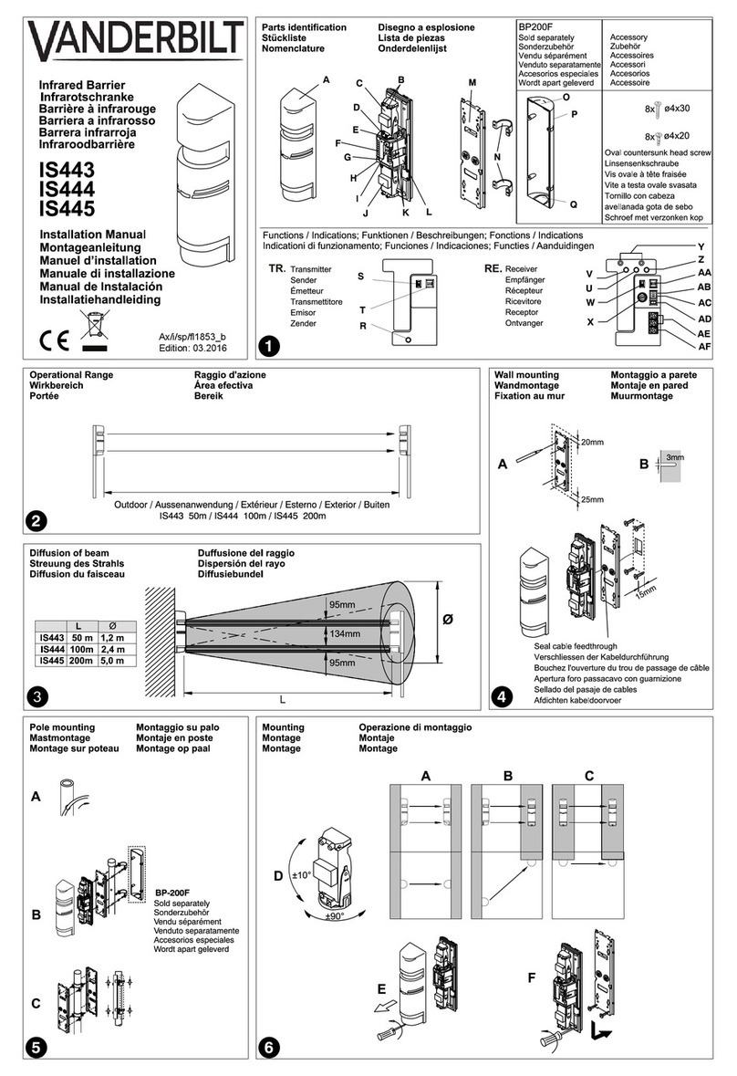
Vanderbilt IS443 User manual

Vanderbilt
Vanderbilt GM710 User manual

Vanderbilt
Vanderbilt GM775 User manual

Vanderbilt
Vanderbilt GM730 User manual

Vanderbilt
Vanderbilt WPIR-EXT Manual

Vanderbilt
Vanderbilt AGB800-AM Manual

Vanderbilt
Vanderbilt AGB800 Manual

Vanderbilt
Vanderbilt GM775LSNi User manual

Vanderbilt
Vanderbilt IR261 User manual

Vanderbilt
Vanderbilt Intrunet E-Line ADM-I12W1 User manual