Spraying Systems AutoJet ES250 User manual

AutoJet® ES250
Electrostatic Chain
Oiler System
ML00ES250F
spray.com
OWNER’S MANUAL

1. Preface ········································································································································ 3
1.1 Important ········································································································································ 3
1.2 How To Use This Manual················································································································ 3
2. Safety ·········································································································································· 3
2.1 General Safety Informaon············································································································ 3
2.2 Unpacking the System····················································································································· 4
3. ES250 Overview ··························································································································· 5
3.1 Electrostacs Spraying Overview··································································································· 5
3.2 System Components and Installaon Requirements····································································· 5
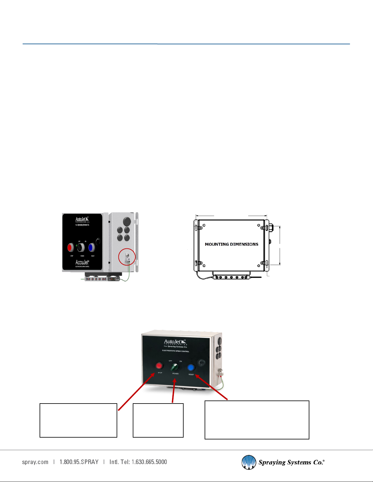
4. Electrostac Spray Control Panel·································································································· 6
4.1 Mounng the Panel and Door Diagram ························································································· 6
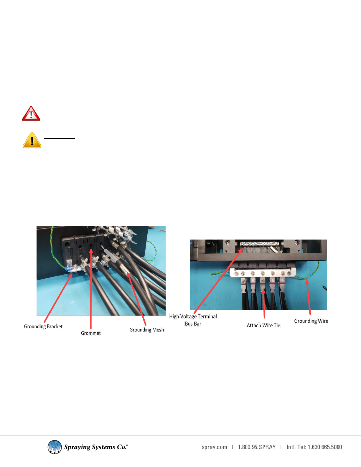
4.2 Connecng the High Voltage Cable································································································ 7
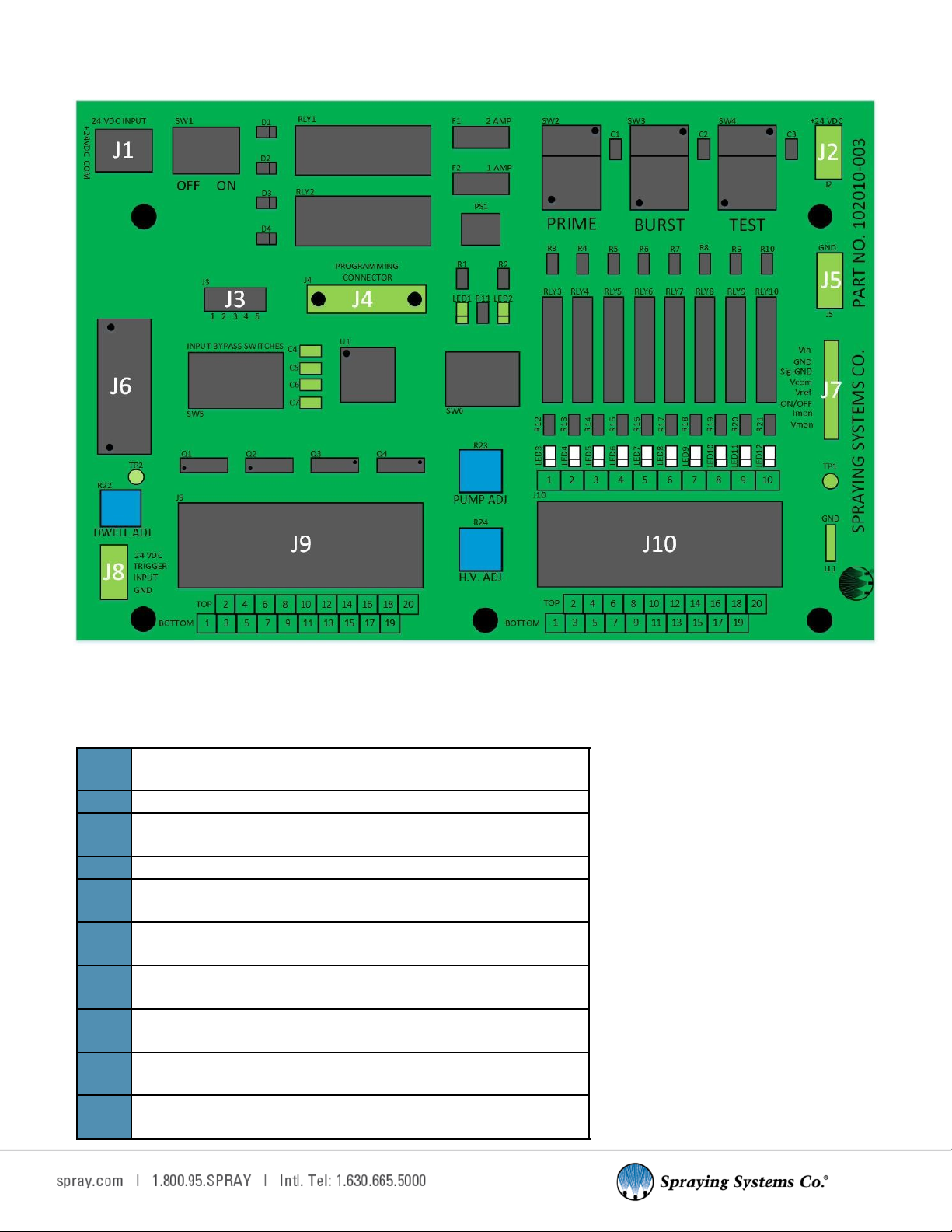
4.3 Circuit Board (PCB) and Terminal Block Diagram··········································································· 8
4.4 Input Details ································································································································· 11
4.5 Output Details ······························································································································ 13
4.6 Potenometers ···························································································································· 16
4.7 System Modes······························································································································ 16
4.8 Oponal PCB Inputs and Connecons ························································································· 18
4.9 Verifying the Spray Control Panel Set Up ···················································································· 19
5. Fluid Reservoir Assembly ··········································································································· 20
5.1 Mounng and Posioning············································································································ 20
5.2 Fluid Reservoir Connecons········································································································· 21
5.3 Lubricant Pump ···························································································································· 22
5.4 Components ································································································································· 23
5.5 Air Pressure Regulator·················································································································· 23
5.6 Parculate Filter··························································································································· 25
5.7 Verifying the Fluid Reservoir Assembly Set Up············································································ 25
6. Electrostac Chain Oiler Spray Nozzle························································································· 26
6.1 Nozzle Overview··························································································································· 26
6.2 Nozzle Connecons······················································································································ 27
6.3 Nozzle Disassembly Procedure ···································································································· 27
6.4 Nozzle Conguraon and Adjustment························································································· 28
7. Faults and Troubleshoong········································································································ 29
7.1 Faults and Fault Codes ················································································································· 29
7.2 Fault LED Status···························································································································· 30
7.3 General System Troubleshoong································································································· 32
7.4 Arc Fault Troubleshoong············································································································ 33
8. Spare and Replacement Parts····································································································· 34
TABLE OF CONTENTS

3
3
1.1 IMPORTANT
The AutoJet® ES250 Electrostac Chain Oiler System and its components are produced, tested, and checked at the
factory. The system can be dangerous if used incorrectly. Read this manual carefully and pay special aenon to any
safety instrucons.
Operators must always follow the general safety instrucons in the working area and aim to prevent accidents.
The manufacturer reserves the right to make changes in standard construcon without prior nocaon.
Images and diagrams in this manual may not be exact representaons of your system conguraon.
1.2 HOW TO USE THIS MANUAL
This manual is intended to be a source of informaon for the operators and technicians who may be installing, inter-
acng with or servicing/maintaining Spraying Systems Co.® systems and components.
This manual contains important safety warnings, installaon instrucons, operang instrucons, troubleshoong
and maintenance informaon.
ICONS
WARNING: The user can be seriously injured, damage their health, and/or damage the system.
CAUTION: Product, process, or environment can be damaged or be in danger if the instrucons are
not followed correctly.
ATTENTION: Supplementary informaon for the user that draws aenon to possible problems.
2.1 GENERAL SAFETY INFORMATION
READ AND FOLLOW INSTRUCTIONS
All safety-related and operang instrucons should be read before the system is operated. Follow all operang
instrucons.
SERVICING
Do not aempt to service this system unless you have been trained or authorized to conduct repairs. Only authorized
and qualied service personnel should aempt to service this system. Service by unauthorized personnel may void any
and all warranes.
WARNING: Before performing any maintenance, make sure electrical power is o and any air/liquid
pressure is bled from the system.
REPLACEMENT PARTS
This system has been designed with components that work together to provide the best system performance. When
replacement parts are required, only Spraying Systems Co.® recommended components should be used to maintain
proper system operaon, electrical and pneumac safety. The use of any unauthorized replacement parts will void any
warranes.
UNINTENDED USE
Use of Spraying Systems Co.® equipment in ways other than those described in the documentaon supplied with the
equipment may result in injury to persons or damage to property. Examples of unintended use of equipment:
SECTION 2
SAFETY
SECTION 1
PREFACE

4
• Using incompable materials or damaged parts
• Making unauthorized modicaons or using unapproved auxiliary equipment
• Removing or bypassing safety guards or interlocks
• Operang equipment in excess of maximum rangs
REGULATIONS AND APPROVALS
Make sure all equipment is rated and approved for the environment in which it is used. Any approvals obtained for
Spraying Systems Co. equipment will be voided if instrucons for installaon, operaon, and service are not followed.
All phases of equipment installaon must comply with federal, state, and local codes.
PERSONAL PROTECTIVE EQUIPMENT
Spraying Systems Co.® strongly recommends the use of appropriate safety equipment when working in potenally
hazardous environments and chemicals. This safety equipment includes, but is not limited to, the following:
• Protecve hat, chemical-resistant safety gloves, and apron
• Safety glasses/face shield, long sleeve shirt and long pants
Users of this product should never place themselves in the path of the spray. Users should consult and follow the
recommendaons of the Safety Data Sheet (SDS) of any chemical or uid sprayed using this system.
PRESSURIZED SYSTEMS
It is important to recognize proper safety precauons when using a pressurized spray system. When dealing with
pressure applicaons, the system pressure should never exceed the lowest rated component. Always know your
system, all component capabilies, maximum pressures and ow rates.
WARNING: Fluids under pressure can penetrate skin and cause severe injury.
ATTENTION: Always remember to carefully read the chemical manufacturer's labels, follow SDS and
all direcons.
WARNING OF SHOCK HAZARD
To reduce the risk of electric shock, do not open the cover on electrical control panel. For service contact
Spraying Systems Co.® at 1-866-321-2250.
WARNING: Plug panels into A GFCI outlet.
WARNING: To prevent injury, avoid contact with potenally hot parts. Components can cause severe
burns. Do not aim the spray at any person or part of the body. Do not place any part of your body
into the spray paern.
USE OF CHEMICAL COMPONENTS
Spraying Systems Co. does not manufacture or supply any of the chemical components used in this equipment and is
not responsible for their eects. Because of the large number of chemicals that could be used and their dierent
chemical reacons, the buyer and user of this equipment should determine compability of the materials used and any
of the potential hazards involved.
2.2 UNPACKING THE SYSTEM
The system components come carefully packaged to protect them from damage. Use cauon when opening the crate.
The crate will contain all parts needed to install the unit. Parts of the unit may be wrapped in bubble wrap. Remove all
of the packaging material wrapping the system. Once unpacked and removed the from the crate, the system is ready
for installaon and connecon.
CAUTION: The packaging may contain exposed cables, hoses, and other components. Always
exercise cauon when opening boxes to avoid accidental damage or slicing of various components.

5
5
3.1 ELECTROSTATICS SPRAYING OVERVIEW
In electrostac spraying, a negave charge is introduced into a uid in the nozzle body through a central charging elec-
trode, which causes the uid to acquire a negave charge. When this negave charge is applied to the uid, this causes
the uid molecules to repel each other, following the principle that molecules with opposite charges will aract and
molecules with like charges will repel. Electrostac spraying relies on the repulsion of these like-charged small uid
droplets.
Aer leaving the nozzle orice, the uid molecules connue to repel each other as they travel, causing the already
small droplets to break up into even smaller droplets. This process will connue unl the repulsive force between the
molecules is no longer strong enough to break the surface tension and split the droplet again.
These ny and uniformly sized droplets retain their negave charges and will be aracted to any neutral, grounded
target nearby with an aracve force stronger than gravity. Electrostac forces pull the liquid molecules towards this
target, thinly and evenly coang the target surface and providing a very high uid transfer eciency
Some benets of electrostac spraying include:
• Low ow rates that allow for less uid usage
• Reduced product and workspace contaminaon due to overspray
• Shorter workspace cleanup mes
• Longer intervals between system maintenance
• More uniform target coangs, typically achieving over 90% transfer eciency
3.2 SYSTEM COMPONENTS AND INSTALLATION REQUIREMENTS
This electrostac system includes the following main components:
• AutoJet® ES250 Electrostac Spray Control Panel
• Fluid Reservoir Assembly
• Electrostac Chain Oiler Spray Nozzle
CUSTOMER REQUIREMENTS FOR INSTALLATION
• Mounng locaons for all components that meet any and all naonal or local safety standards
• 40 psi (minimum) shop air connecon
• 24 VDC power supply to provide power to the control panel’s circuit board, the solenoid valve connecon, and the
high voltage power supply (HVPS) —2.5 amp minimum
REQUIRED TOOLS FOR INSTALLATION
• 15 mm open ended wrench and 27 mm open ended wrench.
• Sloed screwdriver 3/8” (9.5 mm) or larger for accessing the panel)
• #2 Phillips head screwdriver (for removing the high voltage terminal block enclosure cover)
• #2 Square bit screwdriver or 3/8” (9.5 mm) sloed screwdriver (for ghtening high voltage terminals)
• 1/8” (0.125 mm) sloed screwdriver (for terminals)
• Wire strippers
SECTION 3
ES250 OVERVIEW

6
SECTION 4
ELECTROSTATIC SPRAY CONTROL PANEL
SPRAY CONTROL PANEL
The AutoJet® ES250 Electrostac Spray Control Panel supplies the required voltage to the electrostac nozzles via a
30,000 VDC (30 kVDC) negave polarity HVPS. At the control panel, the operator can adjust the applied voltage, pump
frequency and start or stop the system modes.
GASKET
The control panel has a gasket installed which creates a seal between the door and the body of the unit. Exercise
cauon when opening the unit door as to not damage the gasket. Debris inside the control panel may cause damage to
the system.
4.1 MOUNTING THE PANEL AND DOOR DIAGRAM
MOUNTING
When selecng a control panel mounng locaon, consider the high voltage cable roung required and your
purchased cable length in relaon to the nozzle mounng locaon. Make sure the control panel is mounted within an
acceptable distance to the nozzle, it is easily accessible to system operators, and the grounding lug is connected to a
grounded GFCI outlet (Figure 4.1).
If mounng the panel to the wall, in a locaon that is close to your nozzles install wall anchors that are designed to
support at least 25 lbs. (11.34 kg) according to the anchor manufacturer’s specicaons. The mounng holes are on
6” (152 mm) centers and are made for 1/4” (6 mm) screws with 3/8” (10 mm) diameter screw heads (Figure 4.1-1).
Figure 4.1-2: Labeled control panel door diagram
Figure 4.1-1: Dimensions and mounng hole paern
SPRAY CONTROL PANEL DOOR LABELED DIAGRAM
The control panel door uses illuminang pushbuons to relay system informaon. The POWER switch will illuminate
when system power is on. The RESET and STOP pushbuons will illuminate related to system operaon and fault
status (Figure 4.1-2).
Reset Pushbuon: Illuminates when no
fault condion is detected.
Push to reset aer correcng a system
fault
Stop Pushbuon:
When pressed, OUTPUT 2
will turn on and pushbuon
will illuminate
Power Switch:
Will illuminate
when the system
is powered on
10.72” (272 mm)
6” (152 mm)
R. 0.13” (3 mm)
Figure 4.1: Grounding lug

7
7
4.2 CONNECTING THE HIGH VOLTAGE CABLE
WARNING: Before installaon, ensure that the spray control panel is turned o and power is
disconnected.
CAUTION: Make sure high voltage cables are properly grounded. Failure to ground may cause a
power surge on the system and damage the control board.
SUGGESTED TOOLS
• A properly sized adjustable wrench (for cord grips)
• Sloed screwdriver (3/8” or larger for accessing the panel)
• #2 Phillips head screwdriver (for removing the high voltage terminal block enclosure cover)
• 1/8” Sloed screwdriver (for terminals)
• Wire strippers
Figure 4.2: Connecng the high voltage cables to the spray control panel.
CABLE CONNECTION PROCESS
• Remove high voltage block cover and silicone gasket
• Slide cables through the grommets in the boom of the control box
• Connect cables to the high voltage terminal block bus bar
• Push cables into clamps on the grounding bracket, conrm grounding mesh is in clip
• Aach wire e around cable and clip
• Make sure grounding wire is connected from grounding bracket to grounding lug and reinstall cover and
silicone gasket
The reset pushbuon strobes and follows the run sequence. This means that while the system is lubricang, the
pushbuon will strobe in sync with the stroke of the piston pump. When the system stops lubricang but the power
remains on, the pushbuon returns to a constant illuminaon.
If a fault is detected, the reset pushbuon will cease illuminaon and the stop pushbuon will begin to illuminate. The
stop pushbuon will pulse in accordance with the number of pulses that have been set for the detected system fault.
See Secon 7.1 Faults and Fault Codes for more informaon.

8
Figure 4.3-1: PCB diagram
PCB TERMINAL BLOCK INFORMATION
The following table contains PCB terminal block descripons.
4.3 CIRCUIT BOARD (PCB) AND TERMINAL BLOCK DIAGRAMS
J1 Input power connecon
24 VDC, 2.5 amp. (Customer supplied)
J2 24 VDC Source
J3 Factory Use Only
Jumpers must be installed in slots 4 and 5
J4 Factory Use Only
J5 Ground Connecon
Provides a ground for components powered by block J2
J6 Panel Pushbuons & Indicators
See Page 17 for diagram
J7 High Voltage Power Supply
See Page 17 for diagram
J8 Factory Use Only
Trigger Input
J9 Input Connecons
See Page 18 for diagram
J10 Output Connecons
See Page 20 for diagram

9
9
TERMINAL BLOCK J2 AND J5 EXAMPLE DIAGRAM
Block J2 provides 24 VDC only and Block J5 is ground only.
This provides the opon to power components such as proximity sensors or pressure switches. If your system
conguraon does not require or necessitate the use of external components, Blocks J2 and J5 will likely go unused.
Figure 4.3-3: Example diagram for connecng external pressure transducers
(or any other components) to the system
TERMINAL BLOCK J1
Terminal Block J1 is used to provide power to the spray control panel via the connector.
Figure 4.3-2: Locaon and connector for Terminal Block J1.

10
SPRAY CONTROL PANEL DOOR SWITCH AND INDICATOR DIAGRAM—BLOCK J6
HIGH VOLTAGE CONNECTION DIAGRAM—BLOCK J7 CONNECTION REFERENCE*
*Connecons come landed from factory.
Figure 4.3-4: Terminal block J6
CONTROLLER DOOR PUSHBUTTON/INDICATOR CONNECTIONS
Terminal Block J6
3 4
X1 X2
X1 X2
1 2
X1 X2
RESET
RESET
STOP
STOP
POWER ON
POWER ON
3 4
12
34
56
78
910
11 12
Interior Front
Panel Switches

11
11
4.4 INPUT DETAILS
WARNING: Maximum temperature rang 120°F (49°C)
ATTENTION: The Electrostac Spray Control Panel requires a customer supplied 24 VDC, 2.5 A.
Inputs 1 thru 10 require 24 VDC and 1.25 mA to energize.
Figure 4.4-1: Input connecons
PRIME
TEST
RUN
BURST
NOZZLE 1
PRESSURE LOW
Typical Input Connections
ONE
TWO
THREE
FOUR
FIVE
SIX
SEVEN
EIGHT
NINE
TEN
ELEVEN
TWELVE
THIRTEEN
FOURTEEN
AIR PRESSURE
Momentary closure = PRIME
Momentary closure = TEST MODE
Maintained closure = RUN MODE
Maintained closure = BURST MODE
Open switch = FAULT 1
Open switch = FAULT 2
Open switch = FAULT 3
Open switch = FAULT 4
24 VDC
24 VDC
24 VDC
24 VDC
24 VDC
24 VDC
24 VDC
24 VDC
24 VDC
Open switch = AIR PRESSURE FAULT
Open switch = OIL LEVEL FAULT
FIFTEEN
SIXTEEN
SEVENTEEN
EIGHTEEN
NINETEEN
TWENTY
Terminal Block J9
RESERVOIR LEVEL
NOZZLE 1
PRESSURE HIGH
NOZZLE 2
PRESSURE LOW
NOZZLE 2
PRESSURE HIGH
1
2
3
4
5
6
7
8
9
10 11
12
13
14
15
16
17
18
20
INPUT 1
INPUT 2
INPUT 3
INPUT 4
INPUT 5
INPUT 10
INPUT 9
INPUT 8
INPUT 7
INPUT 6
Open switch = OIL LEVEL
24 VDC
19 24 VDC
INPUT CONNECTIONS: J9 TERMINAL BLOCK
Open switch = AIR PRESSURE FAULT
Open Switch = FAULT 4
24 VDC
Open Switch = FAULT 3
Open Switch = FAULT 2
24 VDC
24 VDC
Maintained closure = BURST MODE
Maintained closure = RUN MODE
24 VDC
24 VDC
Momentary closure
= TEST MODE
24 VDC
Momentary closure
= PRIME MODE
24 VDC
24 VDC
Open switch = FAULT 1
RESERVOIR LEVEL SWITCH

12
INPUT DESCRIPTIONS: J9 TERMINAL BLOCK
Not all inputs need to be used. The user should determine which inputs are most important for the applicaon.
Odd numbered connecons are for +24 VDC power source; even numbered connecons are for connecon to posive
side of the load.
INPUT TERMINAL
CONNECTION
DESCRIPTION
11 & 2 Momentary Closure = PRIME MODE
A momentary closure in this circuit acvates PRIME MODE. (ref. prime
mode descripon in System Modes secon)
23 & 4 Momentary Closure = TEST MODE
A momentary closure in this circuit acvates TEST MODE. (ref. test mode
descriponin System Modes secon)
35 & 6 Maintained Closure = RUN MODE
A momentary closure in this circuit acvates RUN MODE. (ref. run mode
descripon System Modes secon)
47 & 8 Maintained Closure = BURST MODE
A momentary closure in this circuit acvates BURST MODE. (ref. burst
mode descripon System Modes secon)
59 & 10 Open Switch = FAULT 1
For use with pressure sensors. System will fault when pressure is below
range.
611 & 12 Open Switch = FAULT 2
For use with pressure sensors. System will fault when pressure is above
range.
713 & 14 Open Switch = FAULT 3
For use with pressure sensors. System will fault when pressure is below
range.
815 & 16 Open Switch = FAULT 4
For use with pressure sensors. System will fault when pressure is above
range.
917 & 18 Open Switch = AIR PRESSURE FAULT
Air pressure guage/sensor to be wired here. System faults if air pressure
falls below set limit on the guage/sensor.
10 19 & 20 Open Switch = OIL LEVEL
Level switch wired here. System will fault when level switch is acve.
Note: Wire colors and terminals.

13
13
These outputs contain PTC Thermistors with a trip rang of 750 mA at 20 °C (68 °F). The PTC Thermistor current pass-
ing capacity must be de-rated 10 percent for each 10 °C increase in ambient temperature.
Example:
The ambient temperature where the control panel is used is 30 °C (86 °F).
The outputs will be de-rated by 10 percent for the 10 °C increase.
(750 mA) (.90) = 675 mA
Outputs 9 and 10:
24 VDC designated outputs, these outputs are powered directly through the circuit board.
These outputs contain PTC Thermistors with a trip rang of 200 mA at 20° C (68° F). The PTC Thermistor current pass-
ing capacity must be de-rated 10 percent for each 10° C increase in ambient temperature.
Example:
The ambient temperature where the control panel is used is 30° C (86° F).
The outputs will be de-rated by 10 percent for the 10°C increase.
(200 mA) (.90) = 180 mA
4.5 OUTPUT DETAILS
Figure 4.5: Output Connecons
Terminal Block J9
ONE
TWO
THREE
FOUR
FIVE
SIX
SEVEN
EIGHT
NINE
TEN
ELEVEN
TWELVE
THIRTEEN
FOURTEEN
FIFTEEN
SIXTEEN
SEVENTEEN
EIGHTEEN
NINETEEN
TWENTY
`
+24 VDC
COM
+24 VDC
COM
Sinking Output Wiring
Sourcing Output Wiring
24 VDC COM
Piston Pump
Solenoid
Diaphragm Pump
Solenoid
24 VDC COM
Output 10 Wiring
Output 9 Wiring
+
+
-
-
Outputs 1 to 8 are isolated general purpose
outputs. If connecting an inductive load such as
a solenoid or relay a snubber circuit or surge
suppression circuit is required to prevent
damage to the output transistors.
Output 9 is a special output designated to
energize a solenoid coil when the system is in
“Lubrication Mode.”
Output 10 is a special output designated to
output a low 20 –80 cycle per minute frequency
to a solenoid (piston pump solenoid) when the
system is in “Lubrication Mode.”
Output Connections
OUTPUT CONNECTIONS: TERMINAL J10

14
OUTPUT DESCRIPTIONS: TERMINAL J10
Not all outputs need to be used. The user should determine which outputs are most important for the applicaon.
Odd numbered connecons are for +24 VDC power source; even numbered connecons are for connecon to posive
side of the load.
OUTPUT DESCRIPTION
TERMINAL
CONNECTION
1
SYSTEM HEALTHY
Energized when the spray control panel is powered on and there are no fault
condions present. Any fault condion will de-energize Output 1. The System Healthy
output is the best way to monitor system status as any alarm and/or power loss will
de-energize this output.
1 & 2
2GENERAL FAULT
Energized when there is a system fault condion present. Output 2 can be used as an
indicator that a fault has occurred and is the opposite of Output 1.
3 & 4
3
FAULT CODE
Sends a series of pulses to indicate a precise fault that occurs. Output 3 can be
connected to a PLC input and used to determine the precise fault that has occurred
by interpreng the Output 3 pulse code.
5 & 6
4ARC FAULT
Energizes if the spray control panel detects a brief current surge though the HVPS.
7 & 8
5NOZZLE PRESSURE FAULT
Energized any me one of the nozzle pressure inputs (5, 6, 7, 8) indicates
unsasfactory nozzle pressure.
9 & 10
6
AIR PRESSURE FAULT
Energized if the air pressure drops below the seng of the air pressure switch.
11 & 12
7
LOW RESERVOIR FAULT
Energized when the reservoir uid level drops below the reservoir level switch.
13 & 14
8FACTORY USE ONLY15 & 16
9
LUBE CYCLE ON
Energized when the system is in Lubricaon, Prime, or Test Mode. The output can be
used to energize the solenoid valve to a diaphragm pump or a stack light indicang
the system status.
17 & 18
10
PISTON PUMP
Provides a low frequency pulse to the piston pump solenoid. The pulse will be output
anyme the spray control panel is in Lubricaon, Prime, or Test mode. The frequency
of the output is controlled by the Pump Adjust Potenometer on the PCB.
19 & 20

15
15
INPUT BYPASS SWITCHES (DIP SWITCH)
Input Bypass Switches allow system operators to toggle Inputs 3-10 on or o. The table below oers a short descrip-
on of each switch, and lists the factory recommended switch seng if appropriate.
Dip Switch Name Switch Posion
Switch 1 – Input 3 bypass
On: Constant Lubricaon Mode
O: If providing external Lubricaon mode input (Recommended)
Switch 2 – Input 4 bypass
On: Constant Burst Mode
O: If providing external Burst Mode input (Recommended)
Switch 3 – Input 5 bypass
On: If not using Nozzle 1 Low Pressure Alarm
O: If Nozzle 1 Low Pressure Alarm is in use
Switch 4 – Input 6 bypass
On: If not using Nozzle 1 High Pressure Alarm
O: If Nozzle 1 High Pressure alarm is in use
Switch 5 – Input 7 bypass
On: If not using Nozzle 2 low pressure alarm
O: If Nozzle 2 low pressure alarm is in use
Switch 6 – Input 8 bypass
On: If not using Nozzle 2 high pressure alarm
O: If Nozzle 2 high pressure alarm is in use
Switch 7 – Input 9 bypass
On: If not using Air Pressure Switch
O: If Air Pressure Switch is in use (Recommended)
Switch 8 – Input 10 bypass
On: If not using Reservoir Level Switch
O: If Reservoir Level Switch is in use (Recommended)
Figure 4.4-2: Input bypass switches in their factory-recommended
posions

16
4.6 POTENTIOMETERS
PUMP Adjustment (PUMP ADJ) – Output 10
The PUMP ADJ potenometer is used to increase or decrease the frequency of Output 10
which aects the pump frequency. The pump frequency is adjustable from 20 – 80 cycles
per minute.
Rotang the potenometer dial clockwise will increase the output frequency.
Rotang the potenometer dial counterclockwise will decrease the output frequency.
HIGH Voltage Adjustment (H.V. ADJ)
The H.V. ADJ potenometer is used to increase or decrease the output of the High Voltage
Power Supply. The High Voltage Power Supply is adjustable from 0 – 30,000 VDC.
Rotang the potenometer dial clockwise will increase the high voltage output.
Rotang the potenometer dial counterclockwise will decrease the high voltage output.
Measuring Exact Output Voltage
The High Voltage Power Supply output can be determined by measuring the DC Voltage
across TP1 (Test Point 1) and Ground. The DC Voltage will be a reference between 0 and
5.0 VDC. To determine the actual High Voltage Output mulply the Voltage across TP1 and
Ground mes 6 kV/volt.
Example:
Voltage across TP1 is measured as 2.2 VDC
(2.2 volts) (6 kV/volt) = 13.2 kV
= 13,200 VDC
DWELL Adjustment (DWELL ADJ)
Factory use only, corresponds with Output 8.
4.7 SYSTEM MODES
PRIME MODE
Terminal Block J9 - INPUT 1 - Connecon 1 & 2 and/or PCB Mounted Pushbuon
Prime mode - will cycle the pump outputs for a period of 60 minutes and should be used during system
installaon or the uid lines to the nozzles need to be lled prior to spraying. The pump cycle during Prime
mode is 120 CPM.
Note: It may require several Prime mode cycles before uid reaches the nozzle opening, depending on
selected uid line length, ow rate, and uid viscosity.
Terminal block J9 -Input 1 is intended for a customer-installed normally-open momentary pushbuon
(Oponal). Input 1 will only be acve if the system is in Standby Mode. This means that the
system cannot be in Lubricaon Mode, Burst Mode, Test Mode, or any fault condion.
—The PCB mounted PRIME pushbuon will be fully funconal whether or not Block J9, Input 1
is connected.
Figure 4.6: PUMP
& High Voltage ADJ
Potenometers
TP1
Figure 4.7-1: PCB
PRIME buon

17
17
If the system is in Prime mode, the following will occur:
• Output 9 will be energized (lubricaon on)
• Output 10 will output a 120 cycle per minute pulse train to rapidly cycle the piston pumps
• The Blue LED indicator on the control panel door will strobe in sync with Output 10
• The Red LED indicator on the PRIME pushbuon located on the PCB will be illuminated, indicang that the
system is in Prime mode
• HVPS will be disabled
• Nozzle 1 & 2 Pressure Low and Pressure High inputs will be disabled
To exit Prime mode, one of the following must occur:
• The system is put into Lubricaon Mode (Input 3 is energized). This automacally terminates Prime mode
• Press the Reset buon on the control panel door
• Press the Prime pushbuon located on the printed circuit board
• Momentarily energize Input 1 (Customer Prime mode input)
• The Prime mode cycle mer expires (60 minutes)
• A fault condion (Low air pressure or Low reservoir level)
TEST MODE
Terminal Block J9 - INPUT 2 - Connecon 3 & 4 and/or PCB Mounted Pushbuon
Test mode will be acve for 15 minutes and should be used to check the system operaon anyme when the system
is in Standby Mode. This means that the system cannot be in Lubricaon mode, Burst mode, Prime mode, or under
any fault condion.
Block J9, Input 2 is intended for a customer-installed normally-open momentary pushbuon (Oponal). The PCB
mounted buon will be fully funconal whether or not the input is connected.
If the system is in Test mode, the following will occur:
• Output 9 will be energized (lubricaon on)
• Output 10 will output a low frequency pulse train (adjustable by the PUMP ADJ potenometer) to cycle the
piston pumps
• The Blue LED indicator on the control panel door will strobe in sync with Output 10
• The Red LED indicator on the TEST pushbuon located on the PCB will be illuminated indicang that the
system is in Test mode
• HVPS will be enabled
To exit Test mode, one of the following must occur:
• The system is put into Lubricaon mode (Input 3 energized). This automacally terminates Test mode
• Press the Reset buon on the control panel door
• Press the TEST pushbuon located on the printed circuit board
• Momentarily energize Input 2 (Customer Test mode input)
• Test mode 15 minute cycle mer expires
• A fault condion
Figure 4.7-2
PCB TEST

18
LUBRICATION MODE
Terminal Block J9 - INPUT 3 - Connecon 5 & 6
Input 3 is the customer lubricaon input. The input can be from a normally-open switch, normally-open relay contacts,
or from a PLC output. When the contacts are closed (24VDC is supplied to the input), the system will be in Lubricaon
mode. When the contacts are open, the system will be in Standby mode.
Lubricaon mode will override both Test and Prime modes. If the Test mode cycle is not complete, and the lubricaon
input is energized, the system will terminate Test mode and the system will enter Lubricaon mode. The system will
not return to Test mode aer the Lubricaon mode is terminated.
If the system is in Lubricaon mode, the following will occur:
• Output 9 will be energized (lubricaon on)
• Output 10 will output a low frequency pulse train (adjustable by the PUMP ADJ potenometer) to cycle the
piston pumps
• The Blue LED indicator on the control panel door will strobe in sync with Output 10
• HVPS will be enabled
To exit Lubricaon Mode:
• Standby mode: Input 3 must be de-energized and SW5 – Dip Switch 1 is an OFF posion
• Fault mode: Any system fault occurs
• System power: OFF
ATTENTION: Burst will only be acve while the system is in Lubricaon mode (Input 3 energized).
BURST MODE
Terminal Block J9 - INPUT 4 - Connecon 7 & 8 or PCB Mounted Pushbuon
When the BURST pushbuon and Input 4 are acvated the system goes into burst mode.
Burst Mode Input - is used to increase the lubricaon volume to 1.25x the current pump frequency setpoint for 24
hours (unless placed into a dierent mode). This allows for a 24-hour period of increased lubricaon, when desired,
without the need to change the PMP ADJ potenometer seng. Maximum burst mode frequency is 100 CPM.
When using the PCB Burst mode pushbuon, the red LED indicator will illuminate.
To exit Burst mode, one of the following must occur:
• The Reset buon on the control panel door is pressed
• The BURST buon on the PCB is pressed
• The 24 hour mode mer expires (PCB Pushbuon)
4.8 OPTIONAL PCB INPUTS AND CONNECTIONS
Terminal Block J8
For factory use only.
Nozzle 1 & 2 Pressure Low & High
Terminal Block J9 - INPUTS 5 through 8 - Connecon 9 through 16
Inputs 5 through 8 will acvate when the nozzle pressure is inadequate. The system must be in Lubricaon mode for 10
seconds before the inputs are enabled. It is intended to be used as nozzle pressure/ow input and allows the pressures
to stabilize before allowing a fault condion to occur.
Figure 4.7-3: PCB
BURST pushbuon

19
19
When a Pressure Fault is detected, the following will occur:
• Output 1 (system healthy) will de-energize
• Output 2 (general fault) will energize indicang a General Alarm
• Output 5 (nozzle pressure fault) will energize
• Outputs 8-10 will de-energize (factory use, lubricaon cycle, piston pump)
• The red stop LED will strobe 2 mes followed by a pause and repeat
• HVPS will be disabled
To clear the fault, the condion must be corrected and the Reset buon must be pressed.
AIR PRESSURE REGULATOR
Terminal Block J9 - INPUT 9 - Connecon 17 & 18
Input 9 is used to monitor if the system has adequate air pressure to properly cycle the pumps.
If the air pressure regulator opens (low system air pressure), the system will go into a Low Air Pressure Fault. The
following will occur:
• Output 1 (system healthy) will de-energize
• Output 2 (general fault) will energize indicang a General Alarm
• Output 3 (fault code) will strobe 10 mes followed by a pause
• Output 6 will energize indicang a “Low Air Pressure Fault”
• Outputs 8-10 (factory use, lubricaon cycle, piston pump) will de-energize
• The red stop LED will strobe 10 mes followed by a pause
• HVPS will be disabled
To clear the fault, the low air pressure condion must be corrected (provide adequate air pressure) and the “Reset”
buon pressed.
RESERVOIR LEVEL SWITCH
Terminal Block J9 - INPUT 10 - Connecon 19 & 20
When the reservoir level switch opens (low reservoir level), the system will go into a Low Oil Level Fault. The following
will occur:
• Output 1 (system healthy) will de-energize
• Output 2 (general fault) will energize indicang a General Alarm
• Output 3 (fault code) will strobe 12 mes followed by a pause
• Output 7 will energize indicang a “Low Reservoir Level Fault”
• Outputs 8-10 (factory use, lubricaon cycle, piston pump) will de-energize
• The red stop LED will strobe 12 mes followed by a pause
• HVPS will be disabled
To clear the fault, the Low Reservoir Fault must be corrected and the “Reset ” buon pressed.
4.9 VERIFYING THE SPRAY CONTROL PANEL SET UP
Verify that the following connecons have been completed:
• 24 VDC has been connected to Terminal J1, and PCB power switch is in the OFF posion
• Both the Spray Control Panel and the target are connected to an “earth” ground or GFCI outlet.

20
5.1 MOUNTING AND POSITIONING
FLUID RESERVOIR ASSEMBLY
The uid reservoir assembly includes pumps, an air pressure regulator with a built in parcle lter, and the uid reser-
voir tank.
The piston pump powers lubricant delivery from the reservoir to the nozzle. The pressure regulator with built in par-
cle lter provides clean, controlled air pressure to the pump for its operaon. The uid reservoir tank provides a sealed
container for the uid being sprayed. The reservoir tank allows for the direct mounng of the air pressure regulator
and pump. The reservoir tank also incorporates a uid level sensor that can stop system operaon via a system fault
when uid levels drop below a safe operang setpoint.
Figure 5.1: Fluid reservoir assembly
With the uid reservoir system conguraon, the components are mounted directly on the reservoir itself. Your
system will ship from the factory with the components already installed on the uid reservoir.
Each electrostac nozzle is powered by a dedicated pump. You will be able to mount up to four (4) pumps to power up
to four (4) nozzles directly to the uid reservoir tank. If your system conguraon includes more than four pumps and
nozzles, a Pump Expansion Kit is available that accommodates an addional four pumps.
• The customer will be responsible for supplying and connecng all liquid and air tubing for the system.
• Posion the uid reservoir assembly below the level that the nozzles will be mounted at.
• The uid reservoir tank must be posioned within 35 of the nozzle mounng locaon.
• If your conguraon does not include the uid reservoir tank, the air pressure switch and piston pumps are to
be mounted in a clean, non-hazardous area below the nozzle mounng level.
WARNING: Make sure all power is disconnected before making any connecons to or from the spray
control panel.
ATTENTION: Please follow any local, state, or naonal regulaons for clearance requirements and
electrical codes.
SECTION 5
FLUID RESERVOIR ASSEMBLY
Tank Lid
Regulator
Assembly
Reservoir Tank
Pump Assembly
Table of contents
Other Spraying Systems Industrial Equipment manuals