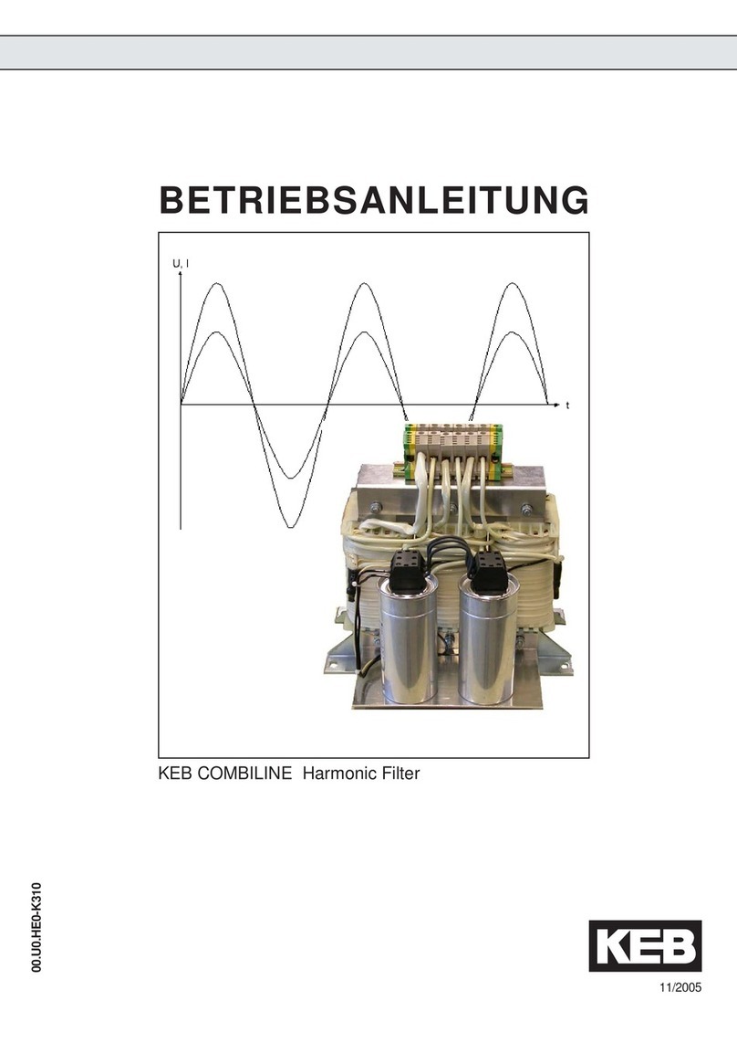
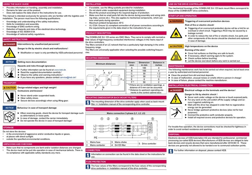
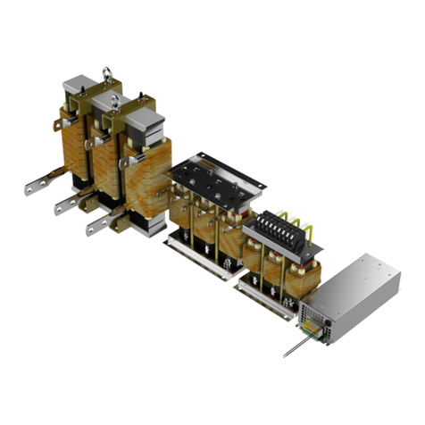
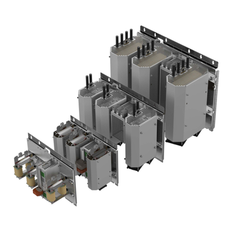
KEBCO COMBILINE E6 Series User manual

Instrctions for use
COMBILINE E6
Installation HF Filter Back mount for F6 Housing 7
Translation of the original manual
Document 20344395 EN 00

Imprint
KEB Automation KG
Suedstraße 38, D-32683 Barntrup
Germany
Tel: +49 5263 401-0 • Fax: +49 5263 401-116
E-Mail: [email protected] • URL: https://www.keb-automation.com
ma_dr_e6-hf-filter-geh7-20344395_en
Version 00 • Edition 17/01/2024

Table of Contents
ma_dr_e6-hf-filter-geh7-20344395_en iii
Table of Contents
1 Introduction ................................................................................................................................................... 7
1.1 Markings................................................................................................................................................ 7
1.1.1 Warnings................................................................................................................................. 7
1.1.2 Information notes .................................................................................................................... 7
1.1.3 Symbols and markers ............................................................................................................. 8
1.2 Laws and guidelines.............................................................................................................................. 8
1.3 Warranty and liability............................................................................................................................. 8
1.4 Support.................................................................................................................................................. 8
1.5 Copyright............................................................................................................................................... 9
1.6 Validity of this manual ........................................................................................................................... 9
1.7 Target group.......................................................................................................................................... 9
2 General Safety Instructions.......................................................................................................................... 10
2.1 Installation............................................................................................................................................. 10
2.2 Electrical installation.............................................................................................................................. 10
2.3 Start-up and operation .......................................................................................................................... 11
3 Product description ...................................................................................................................................... 12
3.1 Intendend use ....................................................................................................................................... 12
3.2 Unintended use..................................................................................................................................... 12
3.3 Part code............................................................................................................................................... 12
3.4 Functional description ........................................................................................................................... 13
3.4.1 IT mains filter .......................................................................................................................... 13
4 Technical data ............................................................................................................................................... 14
4.1 Operating conditions ............................................................................................................................. 14
4.1.1 Climatic ambient conditions .................................................................................................... 14
4.1.2 Mechanical ambient conditions............................................................................................... 14
4.1.3 Chemical/mechanical active substances ................................................................................ 14
4.1.4 Electrical operating conditions ................................................................................................ 15
4.2 Electrical data........................................................................................................................................ 15
4.2.1 NHF combinations .................................................................................................................. 15
4.2.2 Fuse protection according to .................................................................................................. 15
4.2.3 Fuse protection according to UL Class J ................................................................................ 16
4.2.4 Fuse protection according to UL type gR / aR........................................................................ 16
4.2.5 Interference suppression level................................................................................................ 16
4.2.6 Insertion loss........................................................................................................................... 16
5 Assembly ....................................................................................................................................................... 18
5.1 Assembly instructions ........................................................................................................................... 18
5.1.1 EMC notes on assembly......................................................................................................... 18
5.2 Mounting the filter/drive controller......................................................................................................... 19
5.3 Mounting direction................................................................................................................................. 19
5.4 Minimum installation distances filter with drive controller...................................................................... 20
5.5 Assembly NHF combination.................................................................................................................. 20
5.6 Dimensions and weights ....................................................................................................................... 21
5.7 Fixing material....................................................................................................................................... 22
6 Electrical connection .................................................................................................................................... 23

Table of Contents KEB Automation KG
iv ma_dr_e6-hf-filter-geh7-20344395_en
6.1 Connection instructions......................................................................................................................... 23
6.2 Mains connection .................................................................................................................................. 23
6.3 Connection description.......................................................................................................................... 24
6.3.1 Ring crimp connector.............................................................................................................. 24
6.3.2 Earth connection screw .......................................................................................................... 24
7 Maintenance, service and disposal ............................................................................................................. 25
7.1 Maintenance.......................................................................................................................................... 25
7.2 Service .................................................................................................................................................. 25
7.3 Disposal ................................................................................................................................................ 26
8 Certification ................................................................................................................................................... 27
8.1 EU Declaration of Conformity E4, E5, E6 ............................................................................................. 28
8.2 UK Declaration of Conformity E4, E5, E6 ............................................................................................. 30
8.3 UL certification ...................................................................................................................................... 31
9 Annex ............................................................................................................................................................. 32
9.1 Measurement diagrams ........................................................................................................................ 32
9.2 Informative values for the use of RCDs ................................................................................................ 32
10 Revision history ............................................................................................................................................ 33
Glossary ......................................................................................................................................................... 34
Index ............................................................................................................................................................... 36

List of Figures
ma_dr_e6-hf-filter-geh7-20344395_en 5
List of Figures
Fig. 1 Schematic diagram HF mains filter for IT, TN and TT systems ............................................................. 13
Fig. 2 Insertion loss 27E6T60-1150 ................................................................................................................. 17
Fig. 3 Permitted mounting orientation .............................................................................................................. 19
Fig. 4 Mounting distances ................................................................................................................................ 20
Fig. 5 Installation distance between HF filter and mains choke ....................................................................... 21
Fig. 6 Dimensions 27E6T60-1150.................................................................................................................... 22
Fig. 7 Connection 3ph choke filter drive controller ........................................................................................... 23
Fig. 8 Connection 27E6T60-1150 .................................................................................................................... 24
Fig. 9 27E6T60-1150 Interference voltage measurement C2.......................................................................... 32

List of Tables KEB Automation KG
6 ma_dr_e6-hf-filter-geh7-20344395_en
List of Tables
Tab. 1 Technical data........................................................................................................................................ 15
Tab. 2 NHF combinations.................................................................................................................................. 15
Tab. 3 Fuse protection according to IEC........................................................................................................... 15
Tab. 4 Absicherung nach UL Class J................................................................................................................ 16
Tab. 5 Fuse protection according to UL type gR / aR ....................................................................................... 16
Tab. 6 Interference suppression level 27E6T60-1150 ...................................................................................... 16
Tab. 7 Description ring crimp connector............................................................................................................ 24
Tab. 8 Description earth connection screw ....................................................................................................... 24
Tab. 9 Informative values with RCD Doepke 4B NK......................................................................................... 32
Tab. 10 Informative values with RCD Doepke 4B SK ......................................................................................... 32

Introduction | 1
ma_dr_e6-hf-filter-geh7-20344395_en 7
1 Introduction
The described devices, accessories, hardware and/or software are products of
KEB Automation KG. The enclosed documents correspond to conditions valid at
printing. Misprint, mistakes and technical changes reserved.
1.1 Markings
1.1.1 Warnings
Certain operations can cause hazards during the installation, operation or there-
after. There is safety information in the documentation in front of these operations.
Warnings contain signal words for the severity of the hazard, the type and/or
source of the hazard, the consequence of non-compliance and the measures to
avoid or reduce the hazard.
DANGER Type and/or source of the hazard.
Leads to death or serious bodily injury if not observed.
a) Measures to avoid the hazard.
b) Can be supplemented by an additional danger sign or pictogram.
WARNING Type and/or source of the hazard.
May cause death or serious injury if not observed.
a) Measures to avoid the hazard.
b) Can be supplemented by an additional danger sign or pictogram.
CAUTION Type and/or source of the hazard.
May cause bodily injury if not observed.
a) Measures to avoid the hazard.
b) Can be supplemented by an additional danger sign or pictogram.
NOTICE Type and/or source of the hazard.
Can cause damage to property if not observed.
a) Measures to avoid the hazard.
b) Can be supplemented by an additional danger sign or pictogram.
1.1.2 Information notes
Indicates to the user a special condition, prerequisite, scope or simplifica-
tion.
This is a reference to further documentation. The bar-
code is for smartphones, the following link is for online
users or for typing.
(► https://www.keb-automation.com/search)

1 | Introduction KEB Automation KG
8 ma_dr_e6-hf-filter-geh7-20344395_en
Notes on conformity for use in the North American or Canadian mar-
ket.
1.1.3 Symbols and markers
✓Condition
a) Action step
➾Result or intermediate result
(≡► Reference
[}8])
Reference to a chapter, table or picture with page reference
ru21 Parameter name or parameter index
(► )Hyperlink
<Strg> Control code
COMBIVERT Lexicon entry
1.2 Laws and guidelines
KEB Automation KG confirms with the CE mark and the EU declaration of conform-
ity that our device complies with the essential safety requirements.
The EU declaration of conformity can be downloaded on demand via our website.
1.3 Warranty and liability
The warranty and liability on design, material or workmanship for the acquired
device is given in the general conditions of sale.
Here you will find our general sales conditions.
(► https://www.keb-automation.com/terms-conditions)
Further agreements or specifications require a written confirmation.
1.4 Support
Through multiple applications, not every possible case has been taken into ac-
count. If you require further information or if problems occur which are not treated
detailed in the documentation, you can request the necessary information via the
local KEB Automation KG agency.
The use of our units in the target products is beyond of our control and
therefore exclusively the responsibility of the customer.
The information contained in the technical documentation, as well as any support
provided verbally, written or through testing, is made to the best of our knowledge
and information regarding intended use of KEB products. However, due to tech-
nical changes, any information provided is considered non-binding and is subject to
change. This also applies to any violation of industrial property rights of a third-
party.
Selection of KEB units in view of their suitability for the intended use must be done
by the user.
Tests can only be carried out within the scope of the intended end use of the
product (Application) by the Customer. They must be repeated, even if only
parts of hardware, software or the unit adjustment are modified.

Introduction | 1
ma_dr_e6-hf-filter-geh7-20344395_en 9
1.5 Copyright
The customer may use the instructions for use as well as further documents or
parts from it for internal purposes. Copyrights are with KEB Automation KG and re-
main valid in its entirety.
Other wordmarks and/or logos are trademarks (™) or registered trademarks (®) of
their respective owners.
1.6 Validity of this manual
These instructions for use are valid for the units specified in the product descrip-
tion. It can be supplemented by corresponding options or special designs. It con-
tains:
• Safety instructions to be observed
• Information on intended use
• Description of the device
• Technical Data
• Installation
• Connection
• Operation
• Maintenance, service and disposal
1.7 Target group
The instructions for use is determined exclusively for electrical personnel. Electrical
personnel for the purpose of this instruction manual must have the following quali-
fications:
• Knowledge and understanding of the safety instructions.
• Skills for installation and assembly.
• Start-up and operation of the product.
• Understanding of the function in the used machine.
• Detection of hazards and risks of the electrical drive technology.
• Knowledge of IEC 60364.
• Knowledge of national safety regulations (e. g. DGUV Regulation 3).

2 | General Safety Instructions KEB Automation KG
10 ma_dr_e6-hf-filter-geh7-20344395_en
2 General Safety Instructions
The products are developed and built according to the state of the art and recog-
nized safety rules. Nevertheless, their use may create dangers to life and limb of
the user or third parties or damage to the machine and other material property.
The following safety instructions have been created by the manufacturer for the
area of electric drive technology. They can be supplemented by local, country- or
application-specific safety instructions. This list is not exhaustive. Non-observance
of the safety instructions by the customer, user or other third party leads to the loss
of all resulting claims against the manufacturer.
NOTICE Hazards and risks through ignorance!
a) Read the instructions for use.
b) Observe the safety and warning instructions.
c) Ask if something is unclear.
2.1 Installation
DANGER
EX
Explosion hazard due to sparking!
a) Do not operate the unit in a potentially explosive environment.
CAUTION Design-related edges and heavy weight
Contusions and bruises
a) Never stand under suspended loads.
b) Wear safety shoes.
c) Secure product accordingly when using lifting tools.
NOTICE Malfunction due to heat accumulation
a) The installation of liquid-cooled drive controllers with back mount braking resist-
ors is not permitted on back mount filters.
2.2 Electrical installation
DANGER Electrical voltage at terminals and in the device!
Danger to life due to electric shock !
üFor any work on the device
a) Switch off the supply voltage.
b) Secure it against switching on.
c) Wait until all drives has been stopped in order that no regenerative energy can
be generated.
d) Await capacitor discharge time (min. 5 minutes). Measure DC voltage at the
terminals.
e) Never bridge upstream protective devices. Also not for test purposes.

General Safety Instructions | 2
ma_dr_e6-hf-filter-geh7-20344395_en 11
2.3 Start-up and operation
CAUTION High temperatures at the unit!
Burning of the skin
a) Cover hot surfaces safe-to-touch.
b) If necessary, attach warning signs on the system.
c) Before any working let the unit cool down.
d) Check the temperature before touching any parts.

3 | Product description KEB Automation KG
12 ma_dr_e6-hf-filter-geh7-20344395_en
3 Product description
The EMC filters of the product series COMBILINE serve to comply with normative limit
values of high-frequency, conducted interference voltages at the mains input of the drive
controllers.
The filters consist of an LC network that has a particularly high attenuation in the entire
frequency range. This reduces the effective leakage current of the drive system.
Device type HF filter
Series COMBILINE E6
Design Back mounted
Suitable for COMBIVERT F6
The COMBILINE E6 filters are characterised by the following features:
• Designed for interference suppression of individual devices.
• They can be used on TN, TT and IT systems.
• Wide rated voltage range.
• High saturation strength, designed for shielded motor cable lengths up to 100 m.
• Increasing the interference immunity of the drive controllers.
• Compact design of the drive system due to back mount filter.
3.1 Intendend use
The filters of the COMBILINE product series are only suitable for use in conjunction with
drive converters. They are intended for installation in electrical systems or machines.
Technical data and information for connection conditions shall be taken from the type
plate and from the instruction manual and must be strictly observed.
3.2 Unintended use
Operation of our products outside the limits specified in the technical data leads to the
loss of any liability claims and specified approvals/acceptances.
3.3 Part code
1. and 2. digit Device size
12…33 Input current 12...840 A
3. and 4. digit Series
E6 COMBILINE E6
5.-7. digit Version
T60 Complete filter including housing
8. digit Design / voltage class
1 Back mount filter / 3-phase / 400 V
3 Side mount filter / 3-phase
4 4-conductor filter
5 NHF filter / 3-phase / 400 V
7 DC filter
9. digit Limit class
0 C1

Product description | 3
ma_dr_e6-hf-filter-geh7-20344395_en 13
1 C2
2 C3
A C2
B C1
10. digit Mains form
0 TN, TT
5 IT, TN, TT
11. digit Version
0 Sequential numbering
3.4 Functional description
3.4.1 IT mains filter
3.4.1.1 Schematic diagram HF mains filter for IT, TN and TT systems
L1
L2
L3
PE
L1'
L2'
L3'
PE
①②
③③
④
Fig.1: Schematic diagram HF mains filter for IT, TN and TT systems
①Mains input (L1, L2, L3) ②Mains output (L1‘, L2‘, L3‘)
③Protective earth (PE) ③Protective earth (PE)
④Insulation resistance to earth typ. 16 MΩ
3.4.1.2 Use at the IT system
The rated voltage between a phase conductor and the earth potential (or the star point in
the IT system) must not exceed 300 V, USA UL: 480 / 277 V.
A short-term disconnection must be ensured when using an IT system.

4 | Technical data KEB Automation KG
14 ma_dr_e6-hf-filter-geh7-20344395_en
4 Technical data
4.1 Operating conditions
4.1.1 Climatic ambient conditions
Storage Standard Class Notes
Ambient temperature EN 60721-3-1 1K4 -25…55 °C
Relative humidity EN 60721-3-1 1K3 5…95 % (without condensation)
Storage height - - Max. 3000 m above NHN
Transportation Standard Class Notes
Ambient temperature EN 60721-3-2 2K3 -25…70 °C
Relative humidity EN 60721-3-2 2K3 95 % at 40 °C (without condensation)
Operation Standard Class Notes
Ambient temperature EN 60721-3-3 3K3 5…40 °C (extended to -10…45 °C)
Relative humidity EN 60721-3-3 3K3 5…85 % (without condensation)
Site altitude - - Max. 2000 m above NHN
From 1000 m, a power reduction of 1 % per 100
m must be taken into account.
4.1.2 Mechanical ambient conditions
Storage Standard Class Notes
Vibration limits EN 60721-3-1 1M1 Vibration amplitude 0.3 mm (2...9 Hz)
Acceleration amplitude 1 m/s² (9...200 Hz)
Shock limit values EN 60721-3-1 1M1 40 m/s²; 22 ms
Transportation Standard Class Notes
Vibration limits EN 60721-3-2 2M1 Vibration amplitude 3.5 mm (2...9 Hz)
Acceleration amplitude 10 m/s² (9...200 Hz)
Shock limit values EN 60721-3-2 2M1 100 m/s²; 11 ms
Operation Standard Class Notes
Vibration limits EN 60721-3-3 3M4 Vibration amplitude 3.0 mm (2...9 Hz)
Acceleration amplitude 10 m/s² (9...200 Hz)
Vibration limits EN 61800-5-1 - Vibration amplitude 0.0075 mm (2...57 Hz)
Acceleration amplitude 10 m/s² (57...150 Hz)
Shock limit values EN 60721-3-3 3M4 100 m/s²; 11 ms
4.1.3 Chemical/mechanical active substances
Storage Standard Class Notes
Contamination gases EN 60721-3-1 1C2 -
Contamination solids EN 60721-3-1 1S2 -
Transportation Standard Class Notes
Contamination gases EN 60721-3-2 2C2 -
Contamination solids EN 60721-3-2 2S2 -
Operation Standard Class Notes
Contamination gases EN 60721-3-3 3C2 -

Technical data | 4
ma_dr_e6-hf-filter-geh7-20344395_en 15
Contamination solids EN 60721-3-3 3S2 -
4.1.4 Electrical operating conditions
4.1.4.1 Device classification
Requirement Standard Class Notes
Overvoltage category EN 61800-5-1 III -
Pollution degree EN 60664-1 2 Non-conductive pollution, occasional condensa-
tion when PDS is out of operation.
4.2 Electrical data
27E6T60-1150
Rated input voltage 400 V
Rated input voltage (UL) 480/277 V
Input voltage range 0…528 V
Peak input voltage 550 V for max. 1 min/h
Mains phases 3
Mains frequency 50/60 Hz ±2 Hz
Mains form TN, TT, IT
Leakage current according to EN 60939-1:
2010 (Annex A9)
6.4 mA @ 400 V; 7.7 mA @ 480 V
Rated input current 315 A
Rated input current (UL) 269 A
Overload (60s) 150 %
Power dissipation 50 W
Construction and protection class IP00
Suitable KEB housing size F6 / 7
Tab.1: Technical data
4.2.1 NHF combinations
NOTICE!If smaller chokes are used due to the design, the choke must be designed
for the current.
HF filter Mains choke xxZ1B04-1007
25 26 27
27E6T60-1150 x x x
Tab.2: NHF combinations
4.2.2 Fuse protection according to
The following table shows the maximum fuse size of type gG with a 1:1 dimension and an
input voltage of 400 V. In case of other dimension, the values are to be designed for the
current and the SCCR rating of the downstream drive controller.
SCCR 30kA SCCR 100kA
27E6T60-1150 355 A -
Tab.3: Fuse protection according to IEC

4 | Technical data KEB Automation KG
16 ma_dr_e6-hf-filter-geh7-20344395_en
4.2.3 Fuse protection according to UL Class J
The following table shows the maximum fuse size of type Class J with a 1:1
dimension and an input voltage of 480 V. In case of other dimension, the val-
ues are to be designed for the current and the SCCR rating of the down-
stream drive controller.
SCCR 5kA SCCR 10kA SCCR 18kA
27E6T60-1150 - - 350 A
Tab.4: Absicherung nach UL Class J
4.2.4 Fuse protection according to UL type gR / aR
The following table shows the maximum fuse size of type gR / aR with a 1:1
dimension and an input voltage of 480 V. In case of other dimension, the val-
ues are to be designed for the current and the SCCR rating of the down-
stream drive controller. The marks approved for UL are depending on the
connected drive controller and are described there accordingly.
SCCR 30kA SCCR 100kA
27E6T60-1150 - 400 A
Tab.5: Fuse protection according to UL type gR / aR
4.2.5 Interference suppression level
To comply with the required limit class the specified motor cable length must not be ex-
ceeded, depending on the switching frequency.
Filters 27E6T60-1150
Interference voltage (limit class EN 61800-3) C2
Rated switching frequency 2 kHz 4 kHz 8 kHz
Maximum motor cable length (low capacitance) 100 m 50 m 30 m
Tab.6: Interference suppression level 27E6T60-1150
4.2.6 Insertion loss
Measurement results of insertion loss in accordance with EN 55017.

Technical data | 4
ma_dr_e6-hf-filter-geh7-20344395_en 17
-10
0
10
20
30
40
50
60
70
80
90
0.01 0.1 1 10 100
f / MHz
Damping / dB
a
b
c
Fig.2: Insertion loss 27E6T60-1150
a Asymmetrical insertion loss (common mode) b Unsymmetrical insertion loss (differential mode)
c Symmetrical insertion loss (0.1Ω/100Ω system)

5 | Assembly KEB Automation KG
18 ma_dr_e6-hf-filter-geh7-20344395_en
5 Assembly
5.1 Assembly instructions
WARNING Holding lugs designed for own weight only!
üToo much weight can cause the lugs to tear out
a) Only transport filters on their own using the holding lugs.
To prevent damage to the product, the following instructions must be observed:
• Make sure that no components are bent and/or insulation distances are
changed.
• In case of mechanical defects, the product must not be put into operation. Com-
pliance with applied standards is no longer guaranteed.
• No moisture or mist may penetrate the product.
• The penetration of dust must be avoided. When installing in a dust-tight housing,
ensure sufficient heat dissipation.
• (≡► Minimum installation distances filter with drive controller [}20]) to sur-
rounding elements.
• Do not cover ventilation openings.
• Install the product in accordance with the specified construction and protection
degree.
• Make sure that no small parts (drilling chips, screws, etc.) fall into the product
during assembly and wiring. This also applies to mechanical components, which
can lose small parts during operation.
During assembly <link linkid="341440780" use="grab">Mechanische Umweltbedin-
gungen</link> are only observed under the following conditions:
• Use fixing material with the described quality.
• Observe tightening torques
see also
2Mechanical ambient conditions [}14]
5.1.1 EMC notes on assembly
90% of the interferences caused by EMC can be prevented by the following meas-
ures:
a) The contact surface of the filter on the mounting plate must be electrically con-
ductive.
b) The contact surface between the drive controller and the filter must be free of
impurities in order to have a low-resistance, large-area transition here as well.
c) Use the optionally available shield connection bracket.
d) The motor shield must be placed over a large area on the shield connection
bracket of the drive controller.
ðElectromagnetic interference can now be dissipated over a large area via the
mass.

Assembly | 5
ma_dr_e6-hf-filter-geh7-20344395_en 19
Electromagnetic compatibility:
(► https://www.keb.de/fileadmin/media/Techinfo/dr/
tn/ti_dr_tn-emc-00011_en.pdf)
5.2 Mounting the filter/drive controller
• Prepare drill holes
• Screw the filter onto the mounting plate.
• Tighten the screws to the specified torque.
• Connect the filter on the mains side (as it is more accessible).
• Screw in the fastening screws for the drive controller until the drive controller can
be hooked in.
• Hook in the drive controller.
• Tighten the screws to the specified torque.
• Connect the output cable to the drive controller.
5.3 Mounting direction
NOTICE!Malfunctions due to heat accumulation with incorrect mounting dir-
ection
a) Mount the device only in the permitted mounting orientation.
Direction of the airflow
Mounting direction:
• vertical
• hanging
Fig.3: Permitted mounting orientation

5 | Assembly KEB Automation KG
20 ma_dr_e6-hf-filter-geh7-20344395_en
5.4 Minimum installation distances filter with drive controller
Fig.4: Mounting distances
Dimension Distance
A 150 mm 6 inch
B 100 mm 4 inch
C 30 mm 1.2 inch
D 0 mm 0 inch
E 0 mm 0 inch
F 1) 50 mm 2 inch
1) Distance between front of drive unit and control cabinet door.
Distances for combination of HF filter and choke see (≡► Assembly NHF combina-
tion [}20]).
5.5 Assembly NHF combination
When HF filter and mains choke are connected together to form an NHF combina-
tion.
• Installation of the mains choke above the filter.
• Distance 150 mm (see drawing)
Other manuals for COMBILINE E6 Series
2
This manual suits for next models
1
Table of contents
Other KEBCO Water Filtration System manuals