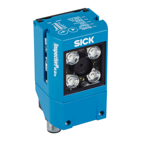
SICK InspectorP621 User manual

OPERATING INSTRUCTIONS
Intelligent Inspection
SensorApps

Described product
Intelligent Inspection (version 1.0)
Manufacturer
SICK AG
Erwin-Sick-Str. 1
79183 Waldkirch
Germany
Legal information
This work is protected by copyright. Any rights derived from the copyright shall be
reserved for SICK AG. Reproduction of this document or parts of this document is only
permissible within the limits of the legal determination of Copyright Law. Any modifica‐
tion, abridgment or translation of this document is prohibited without the express writ‐
ten permission of SICK AG.
The trademarks stated in this document are the property of their respective owner.
© SICK AG. All rights reserved.
Original document
This document is an original document of SICK AG.
2O P E R A T I N G I N S T R U C T I O N S | Intelligent Inspection 8025818/0000/2020-06 | SICK
Subject to change without notice

Contents
1 About this document........................................................................ 4
1.1 Information on the operating instructions.............................................. 4
1.2 Explanation of symbols............................................................................ 4
1.3 Further information................................................................................... 5
2 Safety information............................................................................ 6
2.1 Intended use............................................................................................. 6
2.2 Improper use............................................................................................. 6
2.3 Internet protocol (IP) technology.............................................................. 6
2.4 Limitation of liability................................................................................. 6
2.5 Modifications and conversions................................................................ 7
2.6 General cybersecurity notice................................................................... 7
2.7 Requirements for skilled persons and operating personnel.................. 7
2.8 Operational safety and particular hazards.............................................. 8
3 Product description........................................................................... 11
3.1 Overview.................................................................................................... 11
3.2 System requirements............................................................................... 11
3.3 Solving a Deep Learning application....................................................... 12
4 Operation............................................................................................ 14
4.1 Installation................................................................................................ 14
4.1.1 SICK AppManager.................................................................... 14
4.1.2 Installing the SensorApp on a device..................................... 14
4.1.3 Installing tools.......................................................................... 15
4.2 User interface........................................................................................... 15
4.3 Run mode.................................................................................................. 16
4.4 Configure mode........................................................................................ 16
4.4.1 Tool tree.................................................................................... 17
4.4.2 System settings......................................................................... 18
4.4.3 Job settings.............................................................................. 18
4.4.4 Saving, importing and exporting a configuration................... 23
5 Annex.................................................................................................. 24
5.1 Licenses.................................................................................................... 24
5.2 Tool box - System...................................................................................... 24
5.2.1 Interfaces tools.......................................................................... 24
5.2.2 Calibration tools......................................................................... 26
5.3 Tool box - Jobs........................................................................................... 27
5.3.1 Analysis tools............................................................................. 27
5.3.2 Results tools.............................................................................. 34
5.3.3 Communication tools.................................................................. 39
CONTENTS
8025818/0000/2020-06 | SICK O P E R A T I N G I N S T R U C T I O N S | Intelligent Inspection 3
Subject to change without notice
1 About this document
1.1 Information on the operating instructions
These operating instructions provide important information on how to use products
from SICK AG. Prerequisites for safe work are:
•Compliance with all safety notes and handling instructions supplied.
•Compliance with local work safety regulations and general safety regulations for
product applications .
The operating instructions are intended to be used by qualified personnel.
NOTE
Read these operating instructions carefully before starting any work, in order to famil‐
iarize yourself with the product and its function.
The instructions constitute an integral part of the product and must be accessible to
staff at all times.
These operating instructions do not provide information on operating the machine or
system in which the product is integrated. For information about this, refer to the oper‐
ating instructions of the specific machine.
1.2 Explanation of symbols
Warnings and important information in this document are labeled with symbols. The
warnings are introduced by signal words that indicate the extent of the danger. These
warnings must be observed at all times and care must be taken to avoid accidents, per‐
sonal injury, and material damage.
DANGER
… indicates a situation of imminent danger, which will lead to a fatality or serious
injuries if not prevented.
WARNING
… indicates a potentially dangerous situation, which may lead to a fatality or serious
injuries if not prevented.
CAUTION
… indicates a potentially dangerous situation, which may lead to minor/slight injuries if
not prevented.
NOTICE
… indicates a potentially harmful situation, which may lead to material damage if not
prevented.
NOTE
… highlights useful tips and recommendations as well as information for efficient and
trouble-free operation.
1 ABOUT THIS DOCUMENT
4O P E R A T I N G I N S T R U C T I O N S | Intelligent Inspection 8025818/0000/2020-06 | SICK
Subject to change without notice

1.3 Further information
NOTE
Further documentation for the device can be found on the online product page at:
•www.sick.com/InspectorP63x
•www.sick.com/InspectorP64x
•www.sick.com/InspectorP65x
•www.sick.com/InspectorP62x
There, additional information has been provided depending on the product, such as:
•Model-specific online data sheets for device variants, containing technical data,
dimensional drawing, and specification diagrams
•EU declarations of conformity for the product family
•Dimensional drawings and 3D CAD dimension models of the device variants in var‐
ious electronic formats
•This documentation, available in English and German, and in other languages if
necessary
•Other publications related to the devices described here
•Publications dealing with accessories
Documents on request
Overview of command strings for the device.
ABOUT THIS DOCUMENT 1
8025818/0000/2020-06 | SICK O P E R A T I N G I N S T R U C T I O N S | Intelligent Inspection 5
Subject to change without notice

2 Safety information
2.1 Intended use
Intelligent Inspection is a SensorApp for the InspectorP6xx family of 2D cameras. The
Intelligent Inspection SensorApp is available on request.
Intelligent Inspection uses Deep Learning-based and vision-based quality inspection by
applying embedded image analysis tools to images acquired by the InspectorP6xx cam‐
era. The results are sent to a control system via external interfaces.
2.2 Improper use
Any use outside of the stated areas, in particular use outside of the technical specifica‐
tions and the requirements for intended use, will be deemed to be incorrect use.
•The device does not constitute a safety component in accordance with the respec‐
tive applicable safety standards for machines.
•The device must not be used in explosion-hazardous areas, in corrosive environ‐
ments or under extreme environmental conditions.
•The device must not be operated in the temperature range below 0 °C.
•Any use of accessories not specifically approved by SICK AG is at your own risk.
WARNING
Danger due to improper use!
Any improper use can result in dangerous situations.
Therefore, observe the following information:
■Device should be used only in accordance with its intended use.
■All information in these operating instructions must be strictly observed.
2.3 Internet protocol (IP) technology
NOTE
SICK uses standard IP technology in its products. The emphasis is placed on availability
of products and services.
SICK always assumes the following prerequisites:
•The customer ensures the integrity and confidentiality of the data and rights
affected by its own use of the aforementioned products.
•In all cases, the customer implements the appropriate security measures, such as
network separation, firewalls, virus protection, and patch management.
2.4 Limitation of liability
Relevant standards and regulations, the latest technological developments, and our
many years of knowledge and experience have all been taken into account when com‐
piling the data and information contained in these operating instructions. The manufac‐
turer accepts no liability for damage caused by:
■Non-adherence to the product documentation (e.g., operating instructions)
■Incorrect use
■Use of untrained staff
■Unauthorized conversions
■Technical modifications
■Use of unauthorized spare parts, consumables, and accessories
2 SAFETY INFORMATION
6O P E R A T I N G I N S T R U C T I O N S | Intelligent Inspection 8025818/0000/2020-06 | SICK
Subject to change without notice

With special variants, where optional extras have been ordered, or owing to the latest
technical changes, the actual scope of delivery may vary from the features and illustra‐
tions shown here.
2.5 Modifications and conversions
NOTICE
Modifications and conversions to the device may result in unforeseeable dangers.
Interrupting or modifying the device or SICK software will invalidate any warranty claims
against SICK AG. This applies in particular to opening the housing, even as part of
mounting and electrical installation.
2.6 General cybersecurity notice
Protection against cybersecurity threats requires a comprehensive and holistic cyberse‐
curity concept that must be continuously monitored and maintained. Such a concept
consists of organizational, technical, process-related, electronic and physical defense
levels and sets up appropriate measures for the different types of risk. SICK's products
and solutions must be regarded as an integral part of this concept.
Information on Cybersecurity can be found at: www.sick.com/psirt .
2.7 Requirements for skilled persons and operating personnel
WARNING
Risk of injury due to insufficient training.
Improper handling of the device may result in considerable personal injury and material
damage.
■All work must only ever be carried out by the stipulated persons.
This product documentation refers to the following qualification requirements for the
various activities associated with the device:
■Instructed personnel have been briefed by the operator about the tasks assigned
to them and about potential dangers arising from improper action.
■Skilled personnel have the specialist training, skills, and experience, as well as
knowledge of the relevant regulations, to be able to perform tasks delegated to
them and to detect and avoid any potential dangers independently.
■Electricians have the specialist training, skills, and experience, as well as knowl‐
edge of the relevant standards and provisions to be able to carry out work on elec‐
trical systems and to detect and avoid any potential dangers independently. In Ger‐
many, electricians must meet the specifications of the BGV A3 Work Safety Regu‐
lations (e.g. Master Electrician). Other relevant regulations applicable in other
countries must be observed.
The following qualifications are required for various activities:
Table 1: Activities and technical requirements
Activities Qualification
Mounting, maintenance ■Basic practical technical training
■Knowledge of the current safety regulations in the workplace
SAFETY INFORMATION 2
8025818/0000/2020-06 | SICK O P E R A T I N G I N S T R U C T I O N S | Intelligent Inspection 7
Subject to change without notice

Activities Qualification
Electrical installation,
device replacement
■Practical electrical training
■Knowledge of current electrical safety regulations
■Knowledge of the operation and control of the devices in their
particular application
Commissioning, configura‐
tion
■Basic knowledge of the WindowsTM operating system in use
■Basic knowledge of the design and setup of the described con‐
nections and interfaces
■Basic knowledge of data transmission
■Knowledge of the programming of image-processing systems
and network components
Operation of the device for
the particular application
■Knowledge of the operation and control of the devices in their
particular application
■Knowledge of the software and hardware environment for the
particular application
2.8 Operational safety and particular hazards
Please observe the safety notes and the warnings listed here and in other chapters of
this product documentation to reduce the possibility of risks to health and avoid dan‐
gerous situations.
Illumination LEDs
The product is fitted with LEDs of risk group 0 or 1 for object illumination, depending on
type.
•The accessible radiation from LEDs of risk group 0 does not pose a risk to human
eyes or skin.
•The accessible radiation from LEDs of risk group 1 poses a slight risk to human
eyes.
LED radiation of the internal illumination unit (variants of the VI55I illumination unit)
NOTE
Only the VI55I integrable illumination units from SICK intended for the application can
be used as internal illumination units.
Risk group 1
•Color of illumination: blue (aperture angle: wide, medium), red or white
•Color of spot: red, green
CAUTION
Warning! Optical radiation: LED risk group 1
The LEDs may pose a danger to the eyes and skin in the event of incorrect use.
■Protect the eyes and skin against radiation.
■Use suitable eye protection.
■Use protective measures such as a screen to shield the radiation.
■Do not open the housing. Opening the housing will not switch off the light source.
Opening the housing may increase the level of risk.
■Comply with the current national regulations on photobiological security of lamps
and lamp systems.
Risk group 2
•Color of illumination: blue (aperture angle: narrow)
2 SAFETY INFORMATION
8O P E R A T I N G I N S T R U C T I O N S | Intelligent Inspection 8025818/0000/2020-06 | SICK
Subject to change without notice

CAUTION
Warning! Optical radiation: LED risk group 2
The LEDs may pose a danger to the eyes in the event of incorrect use.
■Protect the eyes and skin against radiation.
■Use suitable eye protection.
■Never point the light source at people.
■Use protective measures such as a screen to shield the radiation.
■Avoid any reflections on people from reflective surfaces. Be particularly careful
during mounting and alignment work.
■Do not open the housing. Opening the housing will not switch off the light source.
Opening the housing may increase the level of risk.
■Comply with the current national regulations on photobiological security of lamps
and lamp systems.
Aiming laser
CAUTION
Optical radiation: Laser class 1
The accessible radiation does not pose a danger when viewed directly for up to 100
seconds. It may pose a danger to the eyes and skin in the event of incorrect use.
■Do not open the housing. Opening the housing may increase the level of risk.
■Current national regulations regarding laser protection must be observed.
CAUTION
Hazardous radiation.
If any operating or adjusting devices other than those specified here are used or other
methods are employed, this can lead to dangerous exposure to radiation. Damage to
the eyes is possible.
■If the product is operated in conjunction with external illumination systems, the
risks described here may be exceeded. This must be taken into consideration by
users on a case-by-case basis.
■Do not look into the light source when it is switched on.
■Comply with the latest version of the applicable regulations on photobiological
safety of lamps and lamp systems as well as on laser protection.
For both radiation types:
It is not possible to entirely rule out temporary disorienting optical effects, particularly
in conditions of dim lighting. Disorienting optical effects may come in the form of daz‐
zle, flash blindness, afterimages, photosensitive epilepsy , depending on parameteriza‐
tion), or impairment of color vision, for example.
CAUTION
Risk of injury due to hot device surface!
■When performing work directly on the product (e.g. cleaning, disassembly), switch
off the device if necessary and allow it to cool down.
SAFETY INFORMATION 2
8025818/0000/2020-06 | SICK O P E R A T I N G I N S T R U C T I O N S | Intelligent Inspection 9
Subject to change without notice

WARNING
Electrical voltage!
Electrical voltage can cause severe injury or death.
■Work on electrical systems must only be performed by qualified electricians.
■The power supply must be disconnected when attaching and detaching electrical
connections.
■The product must only be connected to a voltage supply as set out in the require‐
ments in the operating instructions.
■National and regional regulations must be complied with.
■Safety requirements relating to work on electrical systems must be complied with.
WARNING
Risk of injury and damage caused by potential equalization currents!
Improper grounding can lead to dangerous equipotential bonding currents, which may
in turn lead to dangerous voltages on metallic surfaces, such as the housing. Electrical
voltage can cause severe injury or death.
■Work on electrical systems must only be performed by qualified electricians.
■Follow the notes in the operating instructions.
■Install the grounding for the product and the system in accordance with national
and regional regulations.
2 SAFETY INFORMATION
10 O P E R A T I N G I N S T R U C T I O N S | Intelligent Inspection 8025818/0000/2020-06 | SICK
Subject to change without notice

3 Product description
3.1 Overview
Intelligent Inspection is a Deep Learning-powered SensorApp for the Deep Learning
InspectorP621 2D cameras. The Intelligent Inspection SensorApp allows the use of
Deep Learning-based image classification to classify and sort objects and to ensure
product quality.
In addition to Deep Learning-based image classification, Intelligent Inspection uses tra‐
ditional rule-based and vision-based quality inspection to ensure that produced items
have the exact qualities required regarding presence and measurements of details.
Intelligent Inspection is configured through a web-based graphical user interface, which
contains a selection of software tools for image analysis, result output, and communi‐
cation. The tools are listed and described in "Tool box - System", page 24 and "Tool
box - Jobs", page 27.
Intelligent Inspection is based on SICK Nova, which allows the user to create and import
additional tools. For a description of how to import a tool through SICK AppManager,
see "Installing tools", page 15. Information on SICK Nova tool development is avail‐
able from the SICK Support Portal, supportportal.sick.com.
The Intelligent Inspection SensorApp is pre-installed on the Deep Learning Inspec‐
torP621 devices (art no 1111871 and 1111870) and is also available on request.
3.2 System requirements
Hardware
The use of the Deep Learning API without limitations requires a special Deep Learning
InspectorP621 2D camera (art no 1111871 or 1111870).
The following devices support the use of Intelligent Inspection, with a limitation of 10
calls to the Deep Learning API:
•InspectorP621
•InspectorP631
•InspectorP632
•InspectorP642
•InspectorP652
•InspectorP654
•SICK AppStudio Emulator (full featured)
Software
•The SICK AppManager software (www.sick.com/SICK_AppManager) is required
for installing or updating the SensorApp on a device.
•InspectorP6xx firmware v 3.2.0 or later is required to run the SensorApp. Down‐
load the firmware from the SICK Support Portal, supportportal.sick.com.
•The dStudio software (https://dstudio.cloud.sick.com/) is required for acquiring a
trained neural network to be used for the Deep Learning-based image classifica‐
tion.
Supported web browsers
•Google Chrome
PRODUCT DESCRIPTION 3
8025818/0000/2020-06 | SICK O P E R A T I N G I N S T R U C T I O N S | Intelligent Inspection 11
Subject to change without notice

3.3 Solving a Deep Learning application
Deep Learning is a subset of Artificial Intelligence (AI):
•AI is defined as any technique that enables computers to mimic human decision
making and problem-solving.
•Deep Learning enables computers to mimic human decision making and problem-
solving by finding patterns in data using neural networks.
Deep Learning-based machine vision is well suited for objects with unpredictable char‐
acteristics, such as naturally grown objects, deformable objects, and objects with com‐
plex and unpredictable defects.
Solving a Deep Learning application involves three important phases:
Figure 1: Solving a Deep Learning application
1Collect training images (Data collection phase)
2Label, train and evaluate (Learning phase)
3Inference on SICK AppSpace device (Inference phase)
Data collection phase
The data collection phase includes the following steps:
•Mounting and integration of the device in production.
•Collecting training images. These should be collected under realistic production
conditions.
•Storing the images.
•
The Image Collection tool in the Intelligent Inspection SensorApp can be used for collect‐
ing and storing training images to an FTP server or SD card. See "Image Collection",
page 41 for more information.
Learning phase
The learning phase includes the following steps:
•Labeling the images that represent the planned classes.1)
•Defining a dataset and the required classes.
•Uploading the presorted images to the respective classes.
•Creating a project by selecting a neural network type that gets trained with the
dataset.
•Initiating or stopping a training session, and monitoring the progress of an active
training session.
•Evaluating the results (online: during and after the training, on your device: with
the trial model)
•Acquiring a model (trained neural network) for usage on your SICK device.
1) Currently not implemented in dStudio software
3 PRODUCT DESCRIPTION
12 O P E R A T I N G I N S T R U C T I O N S | Intelligent Inspection 8025818/0000/2020-06 | SICK
Subject to change without notice

The cloud solution dStudio (https://dstudio.cloud.sick.com/) guides the user through
the learning phase and provides training results that can be evaluated online.
Inference phase
The inference phase includes the following steps:
•Uploading the model to the device.
•Classifying new images with the downloaded model directly on the device.
The Deep Learning Classification tool in the Intelligent Inspection SensorApp can be used
for uploading the model to the device and classifying new images with the uploaded
model. See "Deep Learning Classification tool", page 28 for more information.
PRODUCT DESCRIPTION 3
8025818/0000/2020-06 | SICK O P E R A T I N G I N S T R U C T I O N S | Intelligent Inspection 13
Subject to change without notice
4 Operation
4.1 Installation
By default, the Intelligent Inspection SensorApp is pre-installed on the Deep Learning
InspectorP621 devices.
•To run a pre-installed SensorApp, proceed to "User interface", page 15 for
instructions on how to open the user interface.
•To install or update the SensorApp on a device, follow the instructions in "Installing
or updating the SensorApp on a device".
•To start, stop or delete an installed SensorApp, use SICK AppManager (see "SICK
AppManager", page 14).
•To install additional tools, see "Installing tools", page 15.
4.1.1 SICK AppManager
A PC running the SICK AppManager software is required for the following actions:
•Installing and updating a SensorApp on a device.
•Starting, stopping, and deleting installed SensorApps.
•Reading and changing the device’s IP address.
•Installing firmware updates.
Download SICK AppManager from www.sick.com/SICK_AppManager.
4.1.2 Installing the SensorApp on a device
The Intelligent Inspection SensorApp is available on request, and must be downloaded
to a PC prior to installing it on a device.
To install the SensorApp on a device, the SICK AppManager software must be installed
on the PC.
NOTE
Before starting the installation, make sure that the network communication settings on
the PC are correctly set up:
•The PC must be on the same network as the device.
•The PC must not use the same IP address as the device.
To install the SensorApp using SICK AppManager:
1. Connect the device to the PC via Ethernet.
2. On the PC, open SICK AppManager.
3. Under the Device Search tab in SICK AppManager, click Scan to search for available
devices on the network.
4. In the list of available devices, select the device where you want to install the Sen‐
sorApp.
5. If the device tab (lower left pane) contains any active applications, right-click the
applications and delete them.
6. Click the Local Packages tab.
7. Drag and drop the SensorApp into the file list.
8. Click Install to install the SensorApp on the device.
✓The SensorApp is now installed and running on the device.
9. To open the user interface, open a web browser window and type the IP address of
the device.
4 OPERATION
14 O P E R A T I N G I N S T R U C T I O N S | Intelligent Inspection 8025818/0000/2020-06 | SICK
Subject to change without notice
4.1.3 Installing tools
In addition to the tools that are included in the SensorApp by default, custom tools can
be installed and integrated in the SensorApp. Tools are installed as .sapk files using
SICK AppManager. Each file may contain one or more tools.
NOTE
The use of additional tools requires that both the SensorApp and the tool are present
on the device.
Follow the steps below to install tools using SICK AppManager. The device must be con‐
nected to the PC via Ethernet.
1. In the SensorApp web user interface, click Save Permanently to avoid losing any data
during the tool installation process.
2. On the PC, open SICK AppManager and click Scan to browse for available devices.
3. In the list of available devices, select the device where Intelligent Inspection is
installed.
4. To download and install a tool directly from SICK AppPool:
a) Click Login to SICK ID (below the Utils menu in SICK AppManager) to log in to
SICK AppPool.
b) Click the AppPool tab.
c) Select the correct tool in the list of available SensorApps.
d) Click Download and install to download the tool to the PC and install it on the
device.
Or:
To install a downloaded tool (.sapk file) from the PC to the device:
a) Click the Local Packages tab in SICK AppManager.
b) Drag and drop the tool into the file list.
c) Click Install to install the tool on the device.
✓The tool is now installed and running on the device.
5. When the tool installation is complete, reload the web browser to view the installed
tool in the user interface.
4.2 User interface
Opening the user interface
To open the user interface from a web browser:
1. Open a web browser window.
2. Type the IP address of the device. The default IP address is 192.168.0.1.
OPERATION 4
8025818/0000/2020-06 | SICK O P E R A T I N G I N S T R U C T I O N S | Intelligent Inspection 15
Subject to change without notice

Overview of the user interface
7 81
2
3
4
5
96 ß
1Mode selection (Run/Configure)
2System/Jobs switch
3Job list
4Toolbox
5Tool tree
6Image source selection
7Image viewer
8Tool pane
9Save, import and export options
ßLanguage selection
àTool help
4.3 Run mode
Run is the default mode for the SensorApp. Use Run mode for inspection of objects in a
real environment, based on the configuration created in Configure mode.
In Run mode, images are acquired continuously or by an external trigger. All acquired
images are analyzed. To decrease the processing time, only some of the acquired
images are displayed in the viewer in the user interface.
NOTE
When the system is in Run mode:
•The communication interfaces are active and communicate with the connected
external devices.
•No changes to the tool tree or tool settings are possible.
•To switch jobs, click the job list in the job handling section in the user interface or
use a Job Selection I/O tool to switch jobs via digital inputs (see "Job Selection I/O
tool", page 25).
4.4 Configure mode
Use Configure mode to set up a configuration for the application of interest.
4 OPERATION
16 O P E R A T I N G I N S T R U C T I O N S | Intelligent Inspection 8025818/0000/2020-06 | SICK
Subject to change without notice

NOTICE
Click Save Permanently in the configuration toolbar to save a configuration to the device's
flash memory. If a configuration is not saved before disconnecting the power to the
device, all settings are lost.
NOTE
All communication interfaces are inactive in Configure mode.
Follow the steps below to set up a configuration:
1. Add tools to the System tool tree and edit the tool settings, see "Tool categories -
System", page 18.
2. Select an image source for the configuration, see "Image source", page 18.
3. Select a job, see "Creating and switching jobs", page 20.
4. Add tools to the job tool tree and adjust the tool settings, see "Tool categories -
Jobs", page 20.
5. Edit the image acquisition settings for the job, see "Editing the image acquisition
settings", page 22.
6. If multiple jobs are required for an application, repeat step 3, 4 and 5 for each job.
7. Save the resulting configuration to the device and export the configuration for
back-up, see "Saving, importing and exporting a configuration", page 23.
4.4.1 Tool tree
The Inspection SensorApp concept is based on a tool tree structure, which contains
defined categories and associated tools. A configuration contains one tool tree for the
system level (see "System settings", page 18) and one additional tool tree for each
created job (see "Job settings", page 18).
The user adapts each tool tree to the application of interest by adding tool instances to
the different categories. The available tools for each category are described in detail in
"Tool box - System", page 24 and "Tool box - Jobs", page 27.
An example of a job tool tree is displayed in figure 2.
12
Figure 2: Example of a job tool tree with added tool instances
1Categories
2Added tool instances
OPERATION 4
8025818/0000/2020-06 | SICK O P E R A T I N G I N S T R U C T I O N S | Intelligent Inspection 17
Subject to change without notice
Adding and removing tool instances
To add a tool instance to a tool tree:
1. Click a category in the tool tree to display its associated tools.
2. Click and drag a tool icon to the correct category in the tool tree to create a new
instance of the tool.
To remove a tool instance from a tool tree, use one of the following options:
•Select the tool instance in the tool tree and press Delete on the PC keyboard. In the
dialog box that appears, click "Yes" to confirm the deletion.
•Click and hold the tool instance in the tool tree until a trash can icon appears,
then click the trash can icon.
Editing the tool settings
Click a tool instance in the tool tree to display its tool pane, which contains all the avail‐
able settings and result parameters. For more information about the settings and result
parameters, click the tool help (Help button) in the tool pane.
4.4.2 System settings
The System page contains a tool tree with tools related to the device interfaces. Tool
instances that are added to the System tool tree are valid for all jobs.
To access and edit the System page, set the System/Jobs toggle (figure 3) to System.
Figure 3: System/Jobs toggle, here set to System
4.4.2.1 Tool categories - System
The System tool categories are listed below. For descriptions of the individual System
tools, see "Tool box - System", page 24. System tool instances are applied to all jobs.
Interfaces
The Interfaces category contains tools that communicate with external devices. Tools in
the Communication category can use the Interfaces tools for communication and data
transmission.
4.4.3 Job settings
The Job page contains settings for individual jobs. Each job consists of a tool tree and a
reference image.
To access and edit the Job page, set the System/Jobs toggle (figure 3) to Jobs.
4.4.3.1 Image source
Use the image source selection buttons on the Job page to select an image source for
the configuration. Each option has a set of associated controls, which are displayed
below the image viewer.
NOTE
The selected image source is only used during the configuration. In Run mode, the
analysis is based on live images.
4 OPERATION
18 O P E R A T I N G I N S T R U C T I O N S | Intelligent Inspection 8025818/0000/2020-06 | SICK
Subject to change without notice

Live image
Set up the configuration based on live images. The Live option is suitable for
configuring in the real inspection environment.
NOTE
•The Live option is not available when using the SICK AppStudio Emulator.
Table 2: Controls available for live images
Control Name Function
Free running Acquire images continuously.
Run triggered Acquire images based on an external trigger.
To enable the Run triggered button:
1 Click the Acquisition category.
2 Select the External trigger on DI1 checkbox in the tool
pane.
Stop Stop the image acquisition.
Trigger Acquire one single image (trigger an image acquisition by
clicking the button).
Update Reference Image Set the currently displayed image as the reference
image. The currently stored reference image is overwrit‐
ten.
Playback image
Set up the configuration based on recorded images, without access to a real
device.
Table 3: Controls for playback images
Control Name Function
Play Display and loop through the images in the target folder.
Pause Pause the playback.
First image Go to the first image in the series.
Next image Step to the next image in the series.
Settings Cycle images (On/Off)
Image folder: The folder where the recorded images are
stored. The folder must be a public folder on the device
or a folder on an SD card. Examples:
/public/myDirectory
/sdcard/0/myDirectory
OPERATION 4
8025818/0000/2020-06 | SICK O P E R A T I N G I N S T R U C T I O N S | Intelligent Inspection 19
Subject to change without notice

Control Name Function
Update Reference Image Set the currently displayed image as the reference
image. The currently stored reference image is overwrit‐
ten.
Reference image
Set up the configuration based on a saved reference image. This option is suit‐
able if there is one particular image that you want to use for the configuration.
•The reference image is job-specific and must be defined for each job.
•To save a reference image, click Update Reference Image (available for the Live and
Playback options).
•A reference image is required for setting the region of interest for the Object Locator
tool.
Table 4: Controls for the reference image
Control Name Function
Reference Image View the saved reference image.
4.4.3.2 Creating and switching jobs
Create a job for each inspection situation and object type. The job list in the upper left
part of the user interface displays the active job.
If there is no configuration saved on the device when opening the SensorApp, a new job
('Job 1') is created automatically.
Adding and removing jobs
Use the buttons next to the job list to add and remove jobs to and from a configuration:
Icon Name Description
Clone current job Create a copy of the currently selected job and add to the configu‐
ration
Add job Add a new job to the configuration
Remove selected
job
Remove the currently selected job from the configuration
Selecting jobs
Click the job list to display and switch between existing jobs.
When the device is restarted, the most recent active job is reactivated (Requirement:
Save Permanently has been done prior to the restart, see "Saving, importing and export‐
ing a configuration", page 23).
4.4.3.3 Tool categories - Jobs
The tool tree structure for each job on the Job page is formed as a workflow, consisting
of the four categories below. For descriptions of the individual tools, see "Tool box -
Jobs", page 27.
4 OPERATION
20 O P E R A T I N G I N S T R U C T I O N S | Intelligent Inspection 8025818/0000/2020-06 | SICK
Subject to change without notice

Other manuals for InspectorP621
2
This manual suits for next models
5
Table of contents
Other SICK Analytical Instrument manuals

SICK
SICK MCS200HW-MP User manual

SICK
SICK MCS300P Manual

SICK
SICK PINSPECTOR 2D User manual

SICK
SICK DL100 Pro User manual

SICK
SICK ZIRKOR Series User manual

SICK
SICK InspectorP621 User manual

SICK
SICK ZIRKOR200 Ex-G User manual

SICK
SICK VICOTEC320 Series User manual

SICK
SICK MCS200HW User manual

SICK
SICK OD Mini Pro User manual