SPYKER SPYDSS-9G User manual

Page 1©2021 Spyker Spreaders/A Brinly-Hardy Co. 1019621-A
Single Nozzle SPYDSS-9G Drop-In Sprayer
!!IMPORTANT
This manual contains information for the safety of persons and property.
Read it carefully before assembly and operation of the equipment!
OPERATOR'S MANUAL
Spyker Spreaders
Contact us at 800.972.6130
www.spyker.com

Page 2English Manual 1019621-A
Table of Contents + Safety
OPERATE SAFELY
Read Before Using:
Pesticides can cause personal injury and harm the envir-
onment when used improperly. Be sure to follow label
recommendations concerning safety and disposal.
SET-UP PROCEDURE
The SPYDSS-9G was pressure tested prior to shipment.
Some components were disassembled for packaging and
shipment. The basic set-up procedure is as follows:
• Remove all contents from inside the tank.
• Remove all contents from the box.
• Report any missing or damaged items to your dealer
immediately.
TABLE OF CONTENTS
Safety . . . . . . . . . . . . . . . . . . . . . . . 2
Parts . . . . . . . . . . . . . . . . . . . . . . 3 - 7
Assembly . . . . . . . . . . . . . . . . . . 8 - 9
Use and Care
Operation & Maintenance . . . . . . 10
Battery Recharging . . . . . . . . . . . 10
Initial Start-Up & Pressure . . . . . 10
Calibration . . . . . . . . . . . . . . . . . 11
Troubleshooting . . . . . . . . . . . . . 12
Accessories . . . . . . . . . . . . . . . . . 13
Warranty . . . . . . . . . . . . . . . . . . . . 14
Observe all safety precautions including
wearing of protective clothing and equipment.
COMPATIBILITY
The SPYDSS-9G is designed to fit the
following spreaders:
SPYKER • S60-12020 • S100-12011
LESCO • 101186
• 105821
• HPS Chariot

Page 3English Manual 1019621-A
BATTERY AND SPRAY WAND
MOUNTING HARDWARE
SPRAYER HANDLE
WAND PARTS
Parts
DO NOT RETURN PRODUCT IF YOU ARE MISSING PARTS. PLEASE CALL: 1 (800) 972-6130
1
3
4
5
2
6
7
No. Part # Qty Description
1 1019634 1 Angle Bracket
2 1019635 2 Wing Nut
3 1019636 2 Mounting Clip
4 1019637 2 Screw #6 x 1/2"
5 1019638 2 Pan Head Screw
6 1019639 2 Fender Washer
71019640 2 Eye Bolt
1019641* 2 Eye Bolt *Optional Alternate (H.C. Battery)
8 1019691 1 Extension Wand
9 1019692 1 Trigger Jet Valve
10 1019693 1 Turbo TeeJet Nozzle Tip
11 1019694 1 Cap Nut
12 1019695 1 Angle Adapter
13 1019654 1 Strainer w/ Check Valve
8
910 13
12
11

Page 4English Manual 1019621-A
Part Explosions
DO NOT RETURN PRODUCT IF YOU ARE MISSING PARTS. PLEASE CALL: 1 (800) 972-6130
ELECTRICAL
COMPONENTS
No. Part # Qty Description
14 1019642 1 Toggle Switch
15 1019643 1 Switch Bracket
16 1019644 1 Pump / Switch Wiring Assembly
17 1019645 1 Screw Clamp
18 1019646 1 Battery
1019647 1 Battery *High Capacity
19 1019648 1 Battery Wiring Assembly
1019649* 1 Battery Wiring Assembly *Optional H.C. Battery
20 1019650 1 Fuse Holder
N/A 1019651 1 20 Amp Fuse
14
16
17
15
19
16
18
20

Page 5English Manual 1019621-A
Part Explosions
DO NOT RETURN PRODUCT IF YOU ARE MISSING PARTS. PLEASE CALL: 1 (800) 972-6130
NOZZLE
AS SE MBLY
No. Part # Qty Description
21 1019652 1 Hose Barb, 1/4 NPT x 3/8 Male
22 1019653 1 Single Swivel Adapter
23 1019654 1 Strainer w/ Check Valve
24 1019655 1 Cap
25 1019656 1 Wide Angle Spray Tip
26 1019657 1 Clearbraid Hose 3/8" ID x 20"
27 1019637 2 Screw #6 x 1/2”
28 1019636 2 Spring Clip
29 1019660 2 Easy Seal Clamp For 3/8" ID Hose
30 1019661 1 3/8" Wing Nut Barb Steel
51 B-6395 1 Cable Tie *Not Illustrated here
22
23
25
24
26
29
30
21
27
28

Page 6English Manual 1019621-A
Part Explosions
DO NOT RETURN PRODUCT IF YOU ARE MISSING PARTS. PLEASE CALL: 1 (800) 972-6130
TANK &
PLUMBING
45
No. Part # Qty Description
31 1019662 1 Poly Tank, 9 Gallon
32 1019663 1 Regulator
33 1019664 1 0-60 SS Liquid Filled Gauge
34 1019665 4 1/2" Close Nipple Hex
35 1019666 4
1/2" MPT x 1/2" Barb
(NOTE: Two of the four Barbs are not visible in
this photo as they are located inside the tank)
36 1019668 2 1/2" Female Tee
( Part list continues on page 7 )
34
44
43
42
41
34
46
47
48
34
40
33
32
31
35
37
39
38
36
50
49

Page 7English Manual 1019621-A
Part Explosions
DO NOT RETURN PRODUCT IF YOU ARE MISSING PARTS. PLEASE CALL: 1 (800) 972-6130
TANK &
PLUMBING
No. Part # Qty Description
37 1019669 1 Clear Braid Hose; 1/2" ID x 3.5"
38 1019670 4 Easy Seal Clamp; for 1/2" ID Hose
39 1019671 1 1/2" FPT x 1/2" Barb Straight Swivel
1019672 1 1/2" ORS x 1/2" Barb Straight *Optional Part
40 1019673 1 ShuroPump3Gpm
1019674 1 FloJet Pump, 5 GPM *Optional Part
41 1019675 1 1/2" FPT x 1/2" Barb Elbow Swivel
1019676 1 1/2" ORS x 1/2" Barb Elbow *Optional Part
42 1019677 1 Clearbraid Hose; 1/2" ID x 10"
43 1019713 1 Banjo Strainer; 1/2" 50 Mesh, Complete
44 1019681 1 Barb Elbow; 1/2" MPT x 1/2" Barb Elbow
45 1019682 1 6" Female Tank Lid; with Vent
46 1019683 4 Machine Screw; SS, # 10-24 x 1”
47 1019684 1 Ball Valve; 1/2" FPT x 1/2" MPT
48 1019685 1 Street Ell; 1/2”
49 1019686 1 NPT Reducer Bushing; 1/2" x 1/4"
50 1019687 1 Retractable Hose; 1/4" x 10'
Not Illustrated:
N/A 1019679 1 50 Mesh Screen
N/A 1019680 1 Strainer Bowl Gasket
N/A 1019688 1 Hose 1/2" ID x 15" (Inside Tank, Suction Line)
N/A 1019689 1 Hose 1/2" ID x 16" (Inside Tank, Return Line)
N/A 1019690 1 Screw Clamp, SS (Inside Tank, Suction Line)

Page 8English Manual 1019621-A
Assembly
1. Clean all debris from the spreader hopper.
Place the empty tank assembly (31) in the spreader
hopper. NOTE: Face the battery mounted toward
the rear.
Fig. 1
3. Attach the spray hose wingnut (30) to the ball
valve (47).
Fig. 3
31
2. Attach the spring mounting clips (28) to the hopper
near the vertical centerline with the supplied
screws (27).
Fig. 2
28
27
4. Snap the hose (26)
into the clips (28)
with the nozzle facing
forward.
Referencing the
photo below:
Align the nozzle-
end of the hose (26)
against the spreader
frame (A). Secure
with a cable tie (51).
NOTE: The nozzle
must be facing
forward.
28
26
Fig. 4-A
Fig. 4-B
51
26
30
47
A

Page 9English Manual 1019621-A
Assembly
8. Connectswivelelbowtting(41) to the pump inlet
port (40).
Fig. 8
7. Connect the battery wiring assembly (19).
Fig. 7
CAUTION!
Screw in the gauge hand-tight,
with only sufficient force to prevent leaking.
Overtightening the gauge can break the
regulator housing (32).
Fig. 9
9. Install the pressure gauge (41).
5. Align the thumb switch (15) with the handle (B) and
attach with a screw clamp (17).
Fig. 5
15
17
6. Install the pump wiring assembly clips (16) to the
thumb switch spades (15).
Fig. 6
15
16
Assembly is complete.
B
19
19
40
41
41
32

Page 10English Manual 1019621-A
Use and Care
!READ BEFORE USING
GENERAL OPERATION &
MAINTENANCE
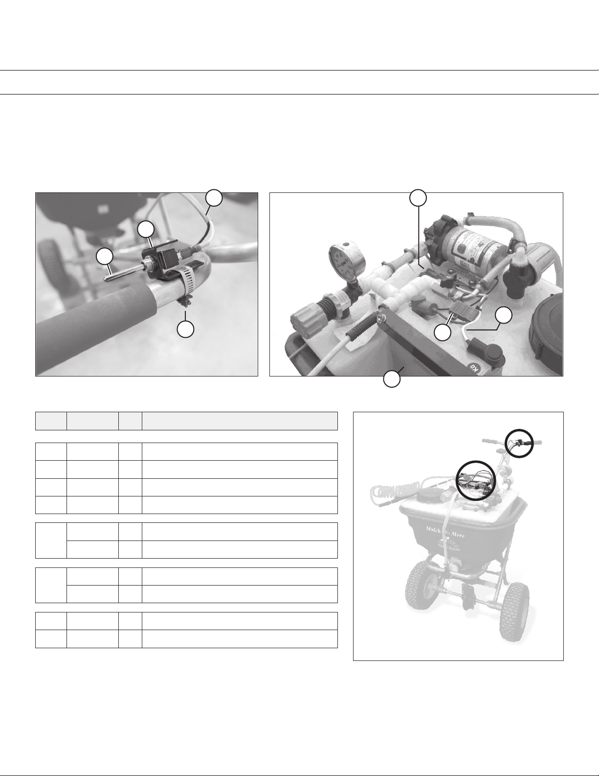
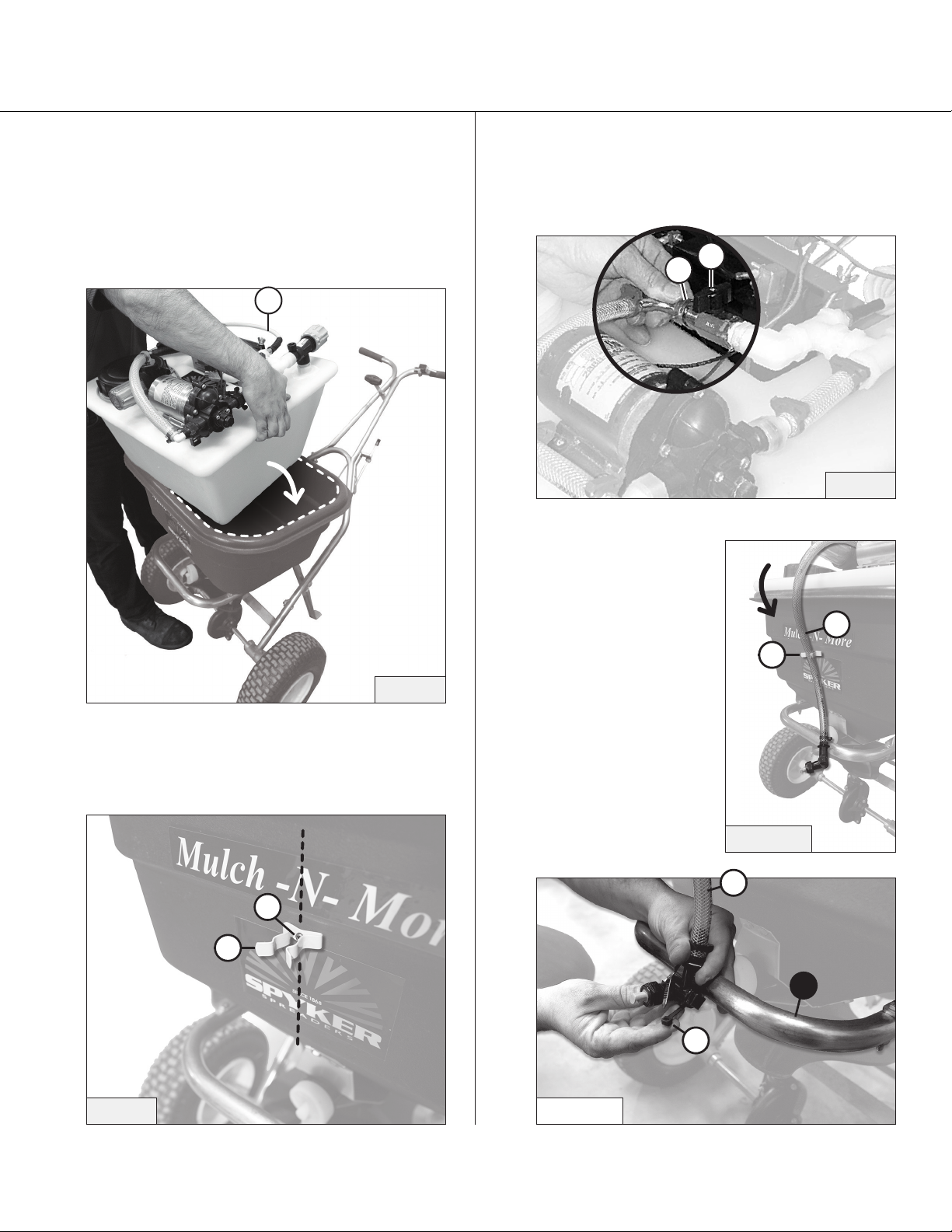
The sprayer pump is turned on and off by the thumb
switch mounted on the handlebar of the spreader. The
hand spray wand is activated by closing the ball valve on
topofthetanktoturnoffowtothefrontnozzle.
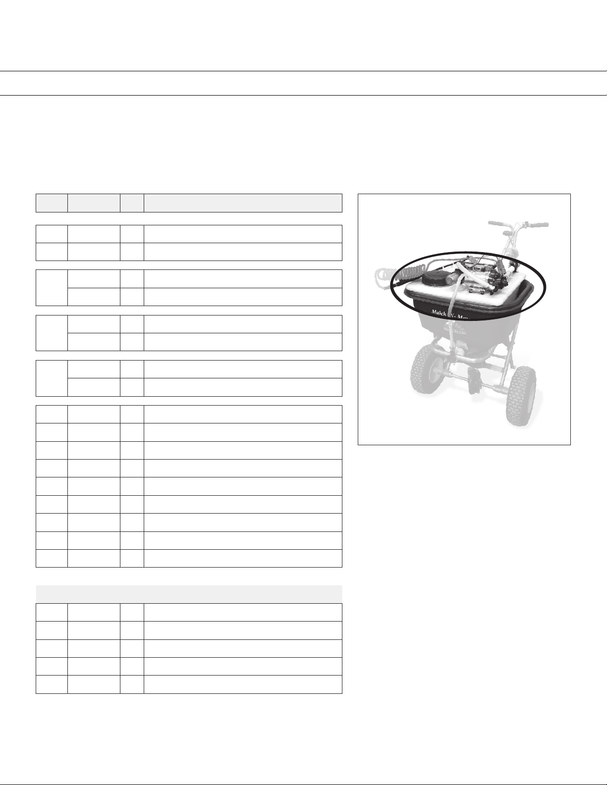
To drain the tank of unused liquids, remove the spray tip
from the wand and pump the remaining liquid into the
proper receptacle.
• Cleanpumplterdaily.
• Preventfromfreezing.
• Cleantipscreenregularly.
• Flushwithwateraftereachuse.
BATTERY RECHARGING
The SPYDSS-9G’s battery is a sealed,
maintenance-free 12-volt battery.
Charging at a low rate (3 amp max.) with an automotive
quality battery charger will extend battery life.
A 110-volt powered plug-in battery charger is available
as an optional accessory to recharge the battery when
not in use. The battery can also be recharged by the
service truck’s charging system by using the optional
vehicle charging kit.
INITIAL START-UP
& PRESSURE TESTING
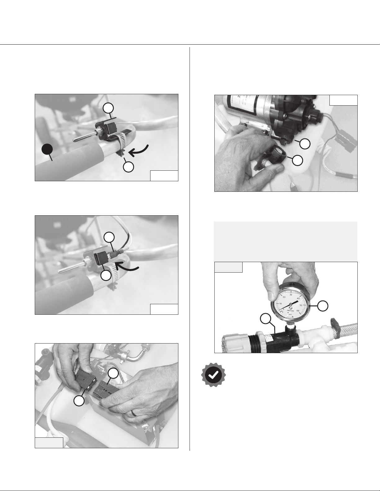
1. Turn the pressure regulator knob counter-clockwise
all the way.
2. Put about one gallon of water in the tank for testing.
3. Be sure that the spray line valve is turned off.
4. Turn on the handlebar thumb switch. You should hear
the pump running and see water moving through the
hoses.
5. Slowly turn the pressure regulator knob clockwise to
increase the pressure. You should notice movement
of the needle on the pressure gauge. Adjust the
pressure to 30 psi for testing.
6. With the spray wand assembled, operate the trigger
valve and check it for leaks. Note the trigger lock.
Also adjust the nozzle and angle adapter orientation
to the desired position.
7. Turn off the switch. Turn on the spray line valve.
8. Turn on the switch and observe the spray pattern
from the spray nozzle. Check the hose assembly
for leaks.
9. Once the unit has been pressure tested and you
are familiar with its operation, you can begin the
calibration procedure.

Page 11English Manual 1019621-A
Use and Care
!READ BEFORE USING
CALIBRATION
The SPYDSS-9G is equipped with a Hypro DeflecTip wide-angle flat flood nozzle. The table below will serve as a ref-
erence for application rates. A working pressure of 15-20 psi will provide adequate coverage. The nozzle should be
adjusted to provide a 60-65 inch spray width with a 4-6 inch overlap of the previous spray pass.
Hypro Nozzle
Number
Pressure
PSI
Capacity
GPM
Gallons per 1000 Sq. Ft.
2 mph 3 mph 4 mph 5 mph
30DT7.5
10 0.8 0.9 0.6 0.4 0.3
15 0.9 1.0 0.7 0.5 0.4
20 1.1 1.2 0.8 0.6 0.5
30 1.3 1.5 1.0 0.7 0.6
Conrming Application Rate
Because walking speeds vary, it is always best to perform a field test to confirm the application rate. The
procedure is simple:
1. Measure an area at least 10,000 square feet.
2. Fill the tank with water.
3. Spray the measured area at 20 psi and at a
comfortable sustainable walking speed.
4. Refill the tank from a calibrated container keeping
track of the amount needed to refill the tank.
5. Divide the number of gallons used by the square footage
of the area sprayed (Expressed in 1000 square foot
increments).
6. Since the tank holds 9 gallons, divide 9 by the result to obtain
the expected coverage per tank full.
Example:
4.5 gallons used
10,000 square feet sprayed
9 gallons / 0.45 = 20
The capacity is 9 gallons, so in this
example a full tank should cover
20,000 square feet.
4.5 gallons / 10
= 0.45 gallons / 1,000 square ft.

Page 12English Manual 1019621-A
Troubleshooting
!READ BEFORE USING
Problem Possible Cause Solution
Pump runs,
but little
or no ow
Battery drained Recharge battery
Tank empty Relltank
Filter clogged Cleanlterscreen
Filter bowl not on tight Tightenlter
Filter gasket faulty or missing Check / Replace gasket
Brokenttingorhose Repair as necessary
Pump needs repair Repair as necessary
Plugged intake line Remove obstruction
Pump has lost prime Re-prime the pump by backing
the Pressure Regulator all the way out.
Pump will not
turn on
Battery dead Recharge battery
Loose or faulty connection Repair as necessary
Faulty switch Repair as necessary
Nozzle not
spraying
Spray valve turned off Turn valve on
Nozzle screen is plugged Clean nozzle screen

Page 13English Manual 1019621-A
Accessories
SPARE SPREADER-MATE BATTERY
KSP18-B17G
One battery can be charging while another battery is in
use. The spare battery comes with battery wire connectors,
fuse assembly and a quick-connect modular plug.
KSP18-TCG
KSP18-TSG
KSP18-B17G
KSP18-C12G
SPREADER-MATE TRUCK CHARGER
KSP18-TCG
The charger allows the sprayer battery to be recharged
from a truck charging system in between jobs.
Included is 20 feet of 10-gauge x 2 wire, 40 amp circuit
breaker, battery wire connectors, and a quick-connect
modular plug for the battery.
ACCUMATE CHARGER
KSP18-C12G
110-Volt powered plug-in charger for overnight
recharging. This is a top quality charger designed
specicallyforAGMbatteries.
TRUCK STAND
KSP18-TSG
This rugged steel frame mounts easily to the truck securing
the sprayer tank assembly when not in use.

Page 14English Manual 1019621-A
1 YEAR LIMITED WARRANTY
This is warranted to the original purchaser only. Spyker will replace parts with defects in
materials and workmanship, for a period of one year from the date of purchase.
The battery and the pump elastomers, which are considered normal wear items, carry a
90-day warranty against defects in materials and workmanship.
Spyker Spreaders will not be liable for any loss, damage or expense including, but not lim-
ited to, consequential or incidental damages, arising from the operation, condition or use of
the item. The sole and exclusive remedy against Spyker Spreaders being the replacement
ofthedefectiveparts.Thiswarrantygivesyouspeciclegalrights,andyoumayalsohave
other rights which vary from state to state.
This express warranty, which is applicable only to the original purchase, is in lieu
of and excludes all other warranties, whether expressed or implied by operation of
law or otherwise, including any warranty of merchantability or tness for particular
purpose.
WARRANTY
SPYKER SPREADERS
Jeffersonville, IN 47130 USA
Phone: 800.972.6130
www.spyker.com
Table of contents
Other SPYKER Paint Sprayer manuals
Popular Paint Sprayer manuals by other brands

Carlisle Fluid Technologies
Carlisle Fluid Technologies DeVILBISS TGS-503 Service manual

Dynalabs
Dynalabs DS-MS-20 product manual

Larson Electronics
Larson Electronics IND-MD-DF-ESF-R1 instruction manual

MATABI
MATABI POLMAX instruction manual

EXTOL PREMIUM
EXTOL PREMIUM SHARE 20V Translation of the original user manual

FBS
FBS 50100 Expert FKM/PA manual