SRS Labs SR400 User manual

MODEL SR400
GATED PHOTON COUNTER
1290-D Reamwood Avenue
Sunnyvale, California 94089
Phone: (408) 744-9040 • Fax: (408) 744-9049
Copyright © 1987 –2018 by SRS, Inc.
All Rights Reserved.
Revision 2.7 (11/2018)


Table of Contents
1
TABLE OF CONTENTS
CONDENSED INFORMATION
Safety and Preparation for Use 3
Specifications 5
Menu Display List 7
Abridged Command List 9
INSTRUMENT OVERVIEW
Signal Inputs / Discriminators 11
Counting 12
Gating 13
Count Modes 14
Outputs 14
Measurement Examples 17
OPERATION
Front Panel Summary 21
Power 21
Liquid Crystal Display 21
Menu Keys 21
Spin Knob 21
Start, Stop, and Reset 21
Instrument Status 22
Counter LED's 22
Inputs 22
Outputs 22
Rear Panel Summary 24
Power Entry Module 24
IEEE-488 Port 24
RS-232 Connector 24
Input 24
Output 24
Front Panel Menus 25
Mode Menu 25
Level Menu 27
Gate Menus 30
Setup Menu 31
Com Menu 31
INSTRUMENT SETUPS
Default Setup / Power On Clear 33
Quick Check 33
2 Photon Pile Up Correction 34
Gated Photon Counting 34
Synchronous or Chopped
Photon Counting 34
REMOTE PROGRAMMING
Communications 37
Command Syntax 37
Status LED's 38
RS-232 Echo 38
Try-out with ASCII Terminal 38
Detailed Command List 39
Mode 39
Levels 40
Gates 41
Front Panel 42
Interface 44
Store/Recall 45
Polled Data 45
Continuous Data 45
Examine Data 46
Status Byte 46
Secondary Status Byte 47
Errors / Data Window 47
Trouble Shooting Interface Problems 47
Common Hardware Problems 47
Common Software Problems 48
RS-232 INTERFACE
Data Communications Equipment 49
Echo 49
Wait Command 49
Termination Sequences 49
Example Programs 49
Microsoft BASIC 50
Microsoft FORTRAN 51
GPIB (IEEE-488) INTERFACE
GPIB Capabilities 53
Serial Polls and Service Requests 53
Example Programs 53
Microsoft BASIC 54
Microsoft C 56
TROUBLESHOOTING
LCD Contrast 59
Fan 59
Front Panel Test 59
Power On Reset 59
Quick Test 59
Counting 60
CALIBRATION AND REPAIR
Signal Input Offset 61
Signal Input Repair 61

Table of Contents
2
USING PHOTOMULTIPLIER TUBES
PMT Selection for Photon Counting 63
Geometry 63
Spectral Response 63
Gain and Risetime 63
Dark Counts 64
PMT Base Design 64
Dynode Biasing 64
Snubbing 66
PMT Base Conclusions 67
Cathode Shielding 67
Preamplifiers 67
Gain Requirement 67
Plateauing a PMT 67
The 'Correct' Way 68
The 'Fast and Pretty Good' Way 68
TYPICAL EXPERIMENT
Energy Levels of Ruby 69
Apparatus 69
Operation 69
Instrument Configuration 70
Computer Data Acquisition 70
CIRCUIT DESCRIPTION
Microprocessor Control 73
Microprocessor System 73
RS-232 Interface 73
GPIB Interface 73
Input Ports 73
Slow Counters 73
Output Ports 73
Front Panel 73
D/A Converter 74
Fast Counters 74
Signal Inputs 74
Discriminators 74
A and B Counters 74
T Counter 75
Start / Stop and Dwell 75
Gate Generators 76
Digital Delay 76
Analog Delay 76
Delay Reset 77
Gates 77
Power Supply 77
PARTS LISTS
Main Assembly 79
Power Supply 93
Miscellaneous 95
SCHEMATIC DIAGRAMS
Signal Amplifiers SR400-1
Discriminators SR400-2
Fast Counters A and B Prescallers SR400-3
Fast Counters T Prescaller SR400-4
Slow Counters (A, B, T) SR400-5
Dwell Timer: Start/Stop SR400-6
Fast Gate Delay Ramps SR400-7
Slow Gate Delay Counters SR400-8
Fast Gate Ramps SR400-9
Width Oscillators SR400-10
Slow Gate Width Counters SR400-11
Microprocessor System SR400-12
Counters and Timers:
Digital Interface 1 SR400-13
Output Ports:
Digital Interface 2 SR400-14
Digital to Analog Converter SR400-15
Power Supply

Safety and Preparation for Use
3
SAFETY AND PREPARATION FOR USE
**** CAUTION ****
This instrument may be damaged if operated with
the LINE VOLTAGE SELECTOR set for the
wrong ac line voltage or if the wrong fuse is
installed.
LINE VOLTAGE SELECTION
The SR400 operates from a 100V, 120V, 220V, or
240V nominal ac power source having a line
frequency of 50 or 60 Hz. Before connecting the
power cord to a power source, verify that the
LINE VOLTAGE SELECTOR card, located in the
rear panel fuse holder, is set so that the correct ac
input voltage value is visible.
Conversion to other ac input voltages requires a
change in the fuse holder voltage card position and
fuse value. Disconnect the power cord, open the
fuse holder cover door and rotate the fuse-pull
lever to remove the fuse. Remove the small
printed circuit board and select the operating
voltage by orienting the printed circuit board to
position the desired voltage to be visible when
pushed firmly into its slot. Rotate the fuse-pull
lever back into its normal position and insert the
correct fuse into the fuse holder.
LINE FUSE
Use 1 Amp slow blow fuse for 100V/120V as well
as 220V/240V.
LINE CORD
The SR400 has a detachable, three-wire power
cord for connection to the power source and to a
protective ground. The exposed metal parts of the
instrument are connected to the outlet ground to
protect against electrical shock. Always use an
outlet which has a properly connected protective
ground.
WARNING REGARDING USE WITH
PHOTOMULTIPLIERS
The signal inputs may be damaged if a
photomultiplier is used improperly with the photon
counter. When left completely unterminated, a
PMT will charge a cable to a few hundred Volts in
a very short time. If this cable is connected to a
signal input, the stored charge may damage the
front-end transistors. To avoid this problem,
provide a leakage path of about 100 KΩ to ground
inside the base of the PMT to prevent charge
accumulation.
CONNECTION TO OTHER INSTRUMENTS
All front panel BNC shields are connected to the
chassis ground and to the power outlet ground via
the power cord. Do not apply any voltage to either
the shields or to the outputs. The outputs are not
protected against connection to any potential other
than ground.

SRS Symbols
4
Symbols that may be found on SRS products

SR400 Specifications
5
SR400 SPECIFICATIONS
OVERVIEW
There are three complete counters identified as A,
B, and T. All counters count up to 200 MHz.
Counter A can count INPUT 1 or the 10 MHz
internal clock. Counter A is gated by AGATE, and
has a count capacity of 109.
Counter B can count INPUT 1 or INPUT 2.
Counter B is gated by BGATE, has a count
capacity of 109and may be used as the preset
counter to determine the count interval.
Counter T can count the internal 10 MHz clock,
INPUT 2, or the gate trigger. This counter may be
preset to determine the count period for up to 25
hours or 9 x 10¹¹ counts, gates, or triggers. The
timer has an accuracy or 25 ppm from 0 to 50∞C.
SIGNAL INPUTS
Bandwidth: dc to 300 MHz
Input impedance: 50 Ohms
Linear range: ± 300 mV (at input)
Input protection: ± 5 Vdc, 50 V for 1 µs
Overload recovery: 5 ns for <10 µs duration
overload
DISCRIMINATORS
Counters A, B, and T have independent
discriminators when counting the signal inputs.
All discriminator levels may be set to a fixed level
or scanned. A rear panel INHIBIT input (TTL
active high) can inhibit the discriminators to stop
the count.
Referenced to the signal inputs:
Discriminator range: -300 mV to +300 mV.
Discriminator slope: Rising or Falling
Resolution: 0.2 mV
Input offset voltage: 1 mV
Minimum pulse input: 10 mV
Pulse pair resolution: 5 ns.
DISC outputs: NIM levels into 50 Ohms
TRIGGER INPUT
Impedance: 10 KOhms
Threshold: ±2.000 Vdc in 1 mV steps
Slope: Rising or Falling
Protection: 15 Vdc, 100 V for 1 µs
GATE GENERATORS
There are two independent gates, AGATE and
BGATE, which enable the A and B counters. Both
gates are triggered by the TRIGGER input. The
gates may be fixed in time or scanned. The GATE
outputs show the positions of the gates with
respect to the discriminator outputs.
Insertion delay: 25 ns
Maximum delay: 999.2 ms
Minimum gate width: 5 ns
Maximum gate width: 999.2 ms or CW
Resolution: 0.1%, 1 ns minimum
Accuracy: 2 ns +1%
Jitter: 200 ps rms +100 ppm
Maximum trigger rate:1 MHz
GATE view outputs: NIM levels into 50 Ohms
GATE view error: < 2 ns
COUNTING MODES
A and B for a period determined by T preSET and
T input.
A ± B for a period determined by T preSET and T
input.
A for a period determined by B preSET and B
input.
SCAN AND DWELL
The number of count PERIODS or data points in a
scan may be set from 1 to 2000. The duration of
one count period is determined by the preset
condition.
The time between consecutive count periods is the
DWELL TIME and can be set from 2 ms to 60 s.
The DWELL output will be TTL high during the
DWELL time. This output can be used to trigger
external devices.
At the end of a scan (of 1 to 2000 count periods)
counting may be programmed to STOP or START
the scan over again.
The START key begins the first count period of
the programmed scan.

SR400 Specifications
6
The STOP key terminates the current count period
and pauses the scan. If scanning, gates and disc
levels are held at their last value. The STOP key
pressed while in a paused condition will reset the
scan and all scanned parameters will return to their
start values. The START key pressed while paused
resumes the scan by starting the next count period.
The DWELL TIME may also be set to
EXTERNAL. In this mode, count periods begin
with the START key or EXTERNAL START
INPUT (TTL rising edge). Count periods
terminate with the preset condition, the STOP key,
or the EXTERNAL STOP INPUT (TTL rising
edge). A STOP key while not counting resets the
scan. This allows completely variable dwell times
and/or counting periods.
All count data is internally buffered for one scan.
Data may be read over the computer interfaces
during or after a scan.
DISPLAY MODE
CONTINUOUS: Displays current counter value
HOLD: Displays final count value
D/A OUTPUT
The front panel D/A Output is proportional to A,
B, A-B, or A+B depending upon the counting
mode selected. The D/A output is updated at the
end of each count period.
There are two rear panel D/A outputs, PORT 1 and
PORT 2. These outputs may be set or scanned
from the front panel or via the computer interface.
Full scale: ± 10 Vdc
Resolution: 12 bits (5 mV)
Current rating: 10 mA
Output Impedance: < 1 Ohm
Accuracy: 0.1% + 5 mV
COMPUTER INTERFACE
IEEE-488 (GPIB) and RS-232 (up to 19.2 kbaud).
Full instrument control and data transmission.
GENERAL
Dimensions: 16" x 13" x 3.5"
Weight: 10 lbs
Power: 35 Watts from 100, 120,
220, or 240 Vac
Warranty: One year parts and labor
on materials and
workmanship

Menu Display List
7
MENU DISPLAY LIST
MODE
COUNT=A,B FOR T PRESET
A=INPUT 1
B=INPUT 2 B SET=1E3
T=10MHZ T SET=1E0 s
N PERIODS=2000 [at 1234]
AT N=STOP DWELL=1E0s
D/A=A
D/A RANGE=LOG
DISPLAY=CONTINUOUS
A GATE
AGATE=SCAN ∆=1.000 µs
A DELAY=1.000 µs
A WIDTH=1.000 µs
B GATE
BGATE=SCAN ∆=1.000 µs
B DELAY=1.000 µs
B WIDTH=1.000 µs
LEVEL
TRIG SLOPE=RISE
TRIG LVL=+2.000 V
A DISC SLOPE=FALL
A DISC=SCAN ∆=-1.0 mV
A DISC LVL=-10.0 mV
B DISC SLOPE=FALL
B DISC=SCAN ∆=-1.0 mV
B DISC LVL=-10.0 mV
T DISC SLOPE=FALL
T DISC=SCAN ∆=-1.0 mV
T DISC LVL=-10.0 mV
PORT1=SCAN ∆=+0.100 V
PORT1 LVL=+0.500 V
PORT2=SCAN ∆=+0.100 V
PORT2 LVL=+0.500 V
SETUP
LCD CONTRAST=12
STORE=3 EXECUTE=>
RECALL=3 EXECUTE=>
COM
GPIB ADDR=23
RS-232 BAUD=9600
RS-232 BITS=8
RS-232 PARITY=NONE
RS-232 WAIT=6
RS-232 ECHO=OFF
DATA=

Menu Display List
8

Abridged Command List
9
ABRIDGED COMMAND LIST
The parameter i is 0,1,or 2 to select counter A,B, or T
MODE
CM j Set COUNT to mode j; A,B(0), A-B(1), A+B(2) for preset T,or A FOR B preset(3).
CI i,j Set counter i to input j; 10 MHz(0), INP 1(1), INP 2(2), TRIG(3).
CP i, n Set counter i preSET to 1 <= n <= 9E11.
NP m Set Number of PERIODS in a scan to 1 <= m <= 2000.
NN Read current count period number or scan position.
NE j Set end of scan mode to mode j; START(1) or STOP (0).
DT x Set DWELL time to 2E-3 <= x <= 6E1 s or EXTERNAL(0).
AS j Set D/A to source j; A(0), B(1), A-B(2), A+B(3).
AM j Set front panel D/A to RANGE j; LOG(0) or LINEAR (1-7).
SD j Set DISPLAY to mode j; CONTINUOUS(0) or HOLD(1).
LEVELS
TS j Set TRIG to SLOPE j; RISE(0) or FALL(1).
TL v Set TRIG LVL to -2.000 <= v <= 2.000 V.
DS i,j Set DISC i to SLOPE j; RISE(0) or FALL(1).
DM i,j Set DISC i to mode j; FIXED(0) or SCAN(1).
DY i,v Set DISC i scan step to -0.0200 <= v <= 0.0200 V.
DL i,v Set DISC i LVL to -0.3000 <= v <= 0.3000 V.
DZ i Read current DISC i LVL (during scan).
PM k, j Set PORT k (1 or 2) to mode j; FIXED(0) or SCAN(1).
PY k,v Set PORT k (1 or 2) scan step to -0.500 <= v <= 0.500 V.
PL k,v Set PORT k (1 or 2) LVL to -10.000 <= v <= 10.000 V.
PZ k Read current PORT k (1 or 2) LVL (during scan).
GATES
GM i,j Set GATE i to mode j; CW(0), FIXED(1), or SCAN(2).
GY i,t Set GATE i DELAY scan step to 0 <= t <= 99.92E-3 s.
GD i,t Set GATE i DELAY to 0 <= t <= 999.2E-3 s.
GZ i Read current GATE i DELAY position (during a scan).
GW i,t Set GATE i WIDTH to 0.005E-6 <= t <= 999.2E-3 s.
FRONT PANEL
CS Count start, same as START key.
CH Count pause, same as STOP key while counting.
CR Count reset, same as STOP key pressed twice.
CK j Simulate key press j.
RR Rotate knob right (CW or UP) 1 step.
RL Rotate knob left (CCW or DOWN) 1 step.
SC Read cursor position. Left(0), right(1), or inactive(2).
MI j Set front panel to mode j; local(0), remote(1), locked-out(2). RS-232 only.
MS string Display string on menu line.
MS Return menu line to normal display.
MD j,k Display line k of menu j.
MM Read menu number of display (j).
ML Read menu line of display (k).

Abridged Command List
10
STORE/RECALL
ST m Store instrument settings to location m (1 to 9).
RC m Recall instrument settings from location m (1 to 9).
RC 0 Recall default settings.
INTERFACE
CL Clear instrument.
SV m Set GPIB SRQ mask to 0 <= m <= 255.
SS Read status byte.
SS j Read bit j(0-7) of status byte.
SI Read secondary status byte.
SI j Read bit j (0-2) of secondary status byte.
SW m Set RS-232 character wait interval to m*3.33 ms 0 <= m <= 25. RS-232 only.
SE j,k,l,m Set RS-232 terminator sequence to j,k,l,m (ASCII codes). RS-232 only.
SE Clear RS-232 terminator sequence to defaults. RS-232 only.
DATA
QA Read last count in counter A.
QB Read last count in counter B.
QA m Read from scan buffer point m(1-2000) for counter A.
QB m Read from scan buffer point m(1-2000) for counter B.
EA Send entire counter A buffer.
EB Send entire counter B buffer.
ET Send entire counter A and B buffer.
FA Start scan and send N PERIODS data points from counter A.
FB Start scan and send N PERIODS data points from counter B.
FT Start scan and send N PERIODS data points from both counters.
XA Read current contents of counter A.
XB Read current contents of counter B.
STATUS BYTE
Bit Description
0 Parameter changed
1 Data ready
2 Scan finished
3 Counter overflow
4 Rate error
5 Recall error
6 Service request
7 Command error
SECONDARY STATUS BYTE
Bit Description
0 Triggered
1 Inhibited
2 Counting
3-7 Unused
Instrument Overview
11
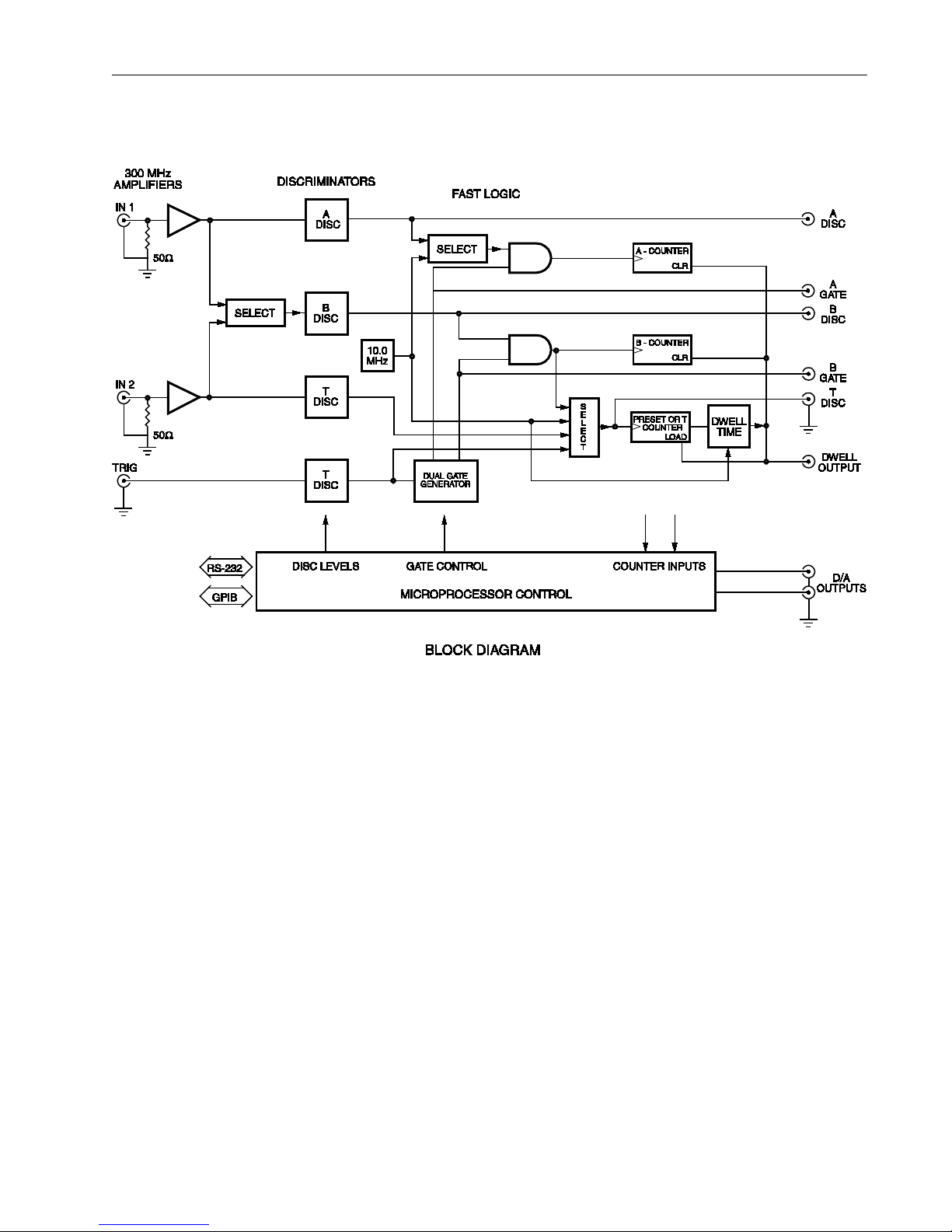
INSTRUMENT OVERVIEW
SR400 OVERVIEW
The SR400 architecture is diagrammed above.
There are three fast counters identified as counters
A, B, and T. All three counters operate at rates up
to 200 MHz. The input to each counter is selected
from a number of sources, including the two
analog signal inputs, the crystal timebase, and the
external trigger input. Counter T is presettable and
determines the measurement period. For pulsed
experiments, counters A and B may also be
synchronized to external events via the two
independent gate generators. The gate generator
provides gates from 5 ns to 1 s in duration with a
delay from external trigger ranging from 25 ns
to 1 s.
SIGNAL INPUTS AND DISCRIMINATORS
There are two independent analog signal inputs
labelled INPUT 1 and INPUT 2. They are
internally terminated into 50 Ω. The inputs can
accept signals of either polarity up to ±300 mV
and are protected to ±5V dc. Each input is
followed by a dc to 300 MHz amplifier. This
allows detection of pulses as small as 10 mV. If
greater sensitivity is required, the SR445A remote
amplifier is available. The SR445A can provide
gains from 5 to 625 at bandwidths up to 350 MHz.
There are three discriminators, one for each
counter. Each discriminator has selectable slope
and a threshold programmable from -300 mV to
+300 mV in 0.2 mV steps (referenced to the
inputs). Pulse-pair resolution is 5 ns and pulses of
either polarity may be detected. Each threshold

Instrument Overview
12
may be programmed to scan in either direction
with selectable step size.
COUNTING
Each counter's input may be selected from a
number of sources. All multiplexing of counter
inputs is done internally to provide accurate timing
and ease of operation. Input cables should rarely
need to be swapped or disconnected to change
measurement modes.
The actual inputs to the counters can be viewed as
NIM level pulses from the DISC outputs on the
front panel. The DISC pulses are negative going
from 0 to -0.7 V. The falling edge is the active or
counted edge regardless of the discriminator slope
setting. The DISC outputs are very useful when
adjusting discriminator thresholds or gate timing.
When the START key is pressed, a START
command is received from the computer interface,
or the EXTERNAL START input is pulsed,
counter T is enabled to count. The COUNT
PERIOD begins with the first pulse from T
counter's input after START. The COUNT
PERIOD enables counters A and B to count their
respective inputs. If the A GATE and B GATE are
CW or continuous, all pulses that occur during the
COUNT PERIOD are counted. If the gates are
enabled, only the pulses that occur during those
gates which fall within the COUNT PERIOD are
counted.
Counter T is presettable from 1 to 9E11. When
counter T reaches the preset count, the COUNT
PERIOD is terminated and counting is halted on
all counters. When the input to counter T is the 10
MHz crystal timebase, the COUNT PERIOD is a
fixed time interval from 100 ns to 25 hours. When
the input is INPUT 2, the COUNT PERIOD is
externally determined and can be as short as 5 ns
and indefinitely long. This mode is used for source
compensation or reciprocal measurements. If the
input is TRIGGER, the COUNT PERIOD is a
fixed number of gates (each trigger provides one
gate). This results in a constant gate aperture time
during each COUNT PERIOD. N+1 Triggers are
required for N gates per period. If the input is B
PRESET, then counter T counts the B DISC
output gated by B GATE. This is for gated ratio or
reciprocal counting.
The SR400 may be programmed to cycle through
1 to 2000 COUNT PERIODS in a single scan. At
the end of the programmed scan, the counters may
be stopped or the scan may be restarted. If the end
of scan mode is STOP, then after the last COUNT
PERIOD in the scan, the counters are halted
indefinitely. A counter RESET is required to
rearm the counters and a START command starts
another scan. If the Number of PERIODS in the
scan is 1, then each START command results in
one COUNT PERIOD. If N PERIODS is greater
than 1, then consecutive COUNT PERIODS are
separated by the DWELL time. The DWELL time
may be set from 2 ms to 60 s. During the DWELL
time, counting is disabled and data may be
transferred or external parameters scanned. The
DWELL OUTPUT is a TTL output which is high
during the DWELL time. At the end of the
DWELL time, the next COUNT PERIOD begins
and the scan continues until N PERIODS have
been measured. If the end of scan mode is
START, one DWELL time separates the last
COUNT PERIOD of the completed scan and the
first COUNT PERIOD of the next scan.
Another DWELL mode is EXTERNAL. In this
mode, the EXTERNAL START input enables
counter T. The COUNT PERIOD begins with the
first pulse to counter T after START. Counting
then proceeds normally until the preset is reached.
At the end of the preset COUNT PERIOD, the
DWELL time is indefinite and the next COUNT
PERIOD starts with the next EXTERNAL START
pulse. In this way, preset COUNT PERIODS may
be synchronized to external events. If externally
determined COUNT PERIODS are desired, then
the preset COUNT PERIOD can be set to a value
much larger than actually required and the
EXTERNAL STOP input used to terminate the
COUNT PERIOD. The COUNT PERIOD then
starts with the first pulse to counter T after
EXTERNAL START and ends with EXTERNAL
STOP. The next EXTERNAL START begins the
next COUNT PERIOD in the scan. When the scan
is finished and the scan end mode is STOP, a
RESET from the front panel or computer interface
is required to reset the scan. If the scan end mode

Instrument Overview
13
is START, the next EXTERNAL START begins
the first COUNT PERIOD of the next scan.
SCANNING
In all scan modes, a number of parameters may be
scanned. These parameters are the three
discriminator thresholds (Pulse Height Analysis),
the two gate delays (Boxcar mode), and the two
D/A output ports (X-axis of recorder, scope, or
analog control of other apparatus).
After each COUNT PERIOD, each scanning
parameter is adjusted by one step. All changes are
made during the DWELL time so that all values
are stable during the COUNT PERIODS. The scan
limits are determined by the start position, the step
size, and the number of PERIODS in a scan. The
range of a scan is N PERIODS times the step size.
When the counters are reset, all scanned
parameters return to their start positions.
GATING
The gate generators may be disabled by setting the
gate modes to CW. In this mode, the gates are
continuously open and counting is enabled solely
by the COUNT PERIOD. This is appropriate for
CW sources or long counting intervals. If the
signal is pulsed or so weak that synchronous (lock-
in) measurement is required, then the gate
generators are required. The gates prevent pulses
that occur outside the time interval of interest from
being counted and improve signal to noise ratio.
When the gates are scanned, the time behavior of
the signal may be recovered.
The gates are triggered by the TRIGGER input.
The TRIGGER threshold is adjustable from -2V to
+2V and slope may be either RISE or FALL. The
discriminated trigger pulse may be viewed through
the T DISC output when the input to counter T is
set to TRIG. This can be helpful when setting the
trigger threshold.
The minimum insertion delay from trigger to gate
is 25 ns. The additional delay may be programmed
from 0 ns to 999.2 ms with a resolution of 1 part in
1000 or 1 ns, whichever is greater. The gate width
is adjustable from 5 ns to 999.2 ms with the same
resolution. The two gates are output as NIM pulses
from the GATE outputs. The gates are open when
the outputs are low. The gate outputs have a
timing accuracy with respect to the discriminator
outputs of 2 ns. This allows accurate timing of fast
gates relative to the signal.
The two gates have independent modes, delays,
and widths. This allows for a variety of
measurements. For example:
1) "Boxcar" mode. The gates are used to enable
the counters only when the signal is present. If the
gates are scanned, then the time profile of the
signal is recovered. Background subtraction can be
included by using one gate for the signal and an
equal width gate on the background, either before
or after the signal. The signal gate may be scanned
while the background gate held fixed. Gated
source compensation is also possible since
counters A and B may count different sources at
the same time or the same source at different
times. In the compensation mode, the COUNT
PERIOD is determined by the gated output of the
B discriminator and the COUNT MODE is A FOR
B PRESET.
2) "Lock-in" or "Chopped" mode. In this case, a
cw signal is chopped on and off. This can be
accomplished with a light chopper such as the
SR540. The light chopper reference output is used
to trigger the gates. The A GATE is positioned
during the "open" cycle and counts signal plus
noise. The B GATE is positioned during the
"closed" cycle and only counts the noise. The
counter outputs are subtracted to give only the
signal. The widths of both gates should be equal
and less than half of the chopper period. This
prevents frequency jitter in the chopper from
affecting the overlap of the gates with the open
and close cycles of the chopper.
When counter T is preset and its input is set to
TRIG, then each COUNT PERIOD consists of a
constant number of gates. N+I triggers are needed
for N gates per preiod. This is the usual mode of
gated operation. However, a number of other
modes are available. For example, if the input is
set to 10 MHz, each COUNT PERIOD consists of
the number of gates which occur during the
COUNT PERIOD time interval. If the input is a
signal input, then counting is both gated and

Instrument Overview
14
source compensated. If the DWELL mode is
EXTERNAL, an EXTERNAL START pulse starts
counting and an EXTERNAL STOP pulse stops
counting. The counters are enabled only during
those gates which occurred between the two
EXTERNAL pulses.
COUNT MODES
The length of a COUNT PERIOD is the time it
takes counter T to reach its preset count. If Ntis
the preset count in counter T, and Raand Rtare the
mean pulse rates of the inputs to counters A and T,
then the COUNT PERIOD is
T = Nt / Rt
The number of counts in counter A will be
A = RaT = RaNt/ Rt
Rate:
If Rt= 10 MHz, then the COUNT PERIOD is a
constant amount of time and
A = Ra( Nt/ Rt) ~ Ra
and counter A measures the mean rate of its input.
Gated:
If Rtis the gate trigger rate and counter A is
gated, then the COUNT PERIOD is Nt/Rtbut the
"effective" time the counter is enabled is NtWa
where Wais the width of A gate and
A = Ra( NtWa) ~ Ra
In this case, counter A measures the mean rate
during the A gate.
Source Compensated:
If Rt is INPUT 2, then the COUNT PERIOD is
determined by the pulse rate of INPUT 2 and the T
discriminator. Count A will be
A = NtRa/ Rt~ Ra / Rt
and is proportional to the ratio of the rates of
counters A and T. If INPUT 2 monitors source
intensity, then the COUNT PERIOD will adjust
for fluctuations in the source. Counter A measures
the ratio of its mean input rate and the mean rate
of INPUT 2.
Reciprocal:
If Rtis INPUT 2, then the COUNT PERIOD is
Nt/Rt. If Rais 10 MHz, then counter A measures
A = RaNt/ Rt= ( RaNt) / Rt~ 1 / Rt
and is proportional to the reciprocal of the count
rate of INPUT 2. Note that each COUNT PERIOD
is determined by Ntcounts of INPUT 2, thus the
measurement time is determined by the signal
strength. Measurements of both strong and weak
signals are made to the same accuracy for constant
signal to noise ratio.
Counter B:
Counter B may be used in all of the above modes
except Reciprocal. Since counter B is completely
independent of counter A, 2 sources of counts may
be measured simultaneously. These sources may
be the same signal or 2 different signals; the
sources may be discriminated at separate
thresholds; they may be non-gated or gated; if
gated, the 2 gates may be independently set.
Almost any measurement can be made.
In addition, counter B has a preset mode called A
FOR B PRESET. In this mode, the input to
counter B is sent to counter T. The COUNT
PERIOD is now determined by the B
discriminator and the B gate. If Rais INPUT 1,
then counter A is source compensated by the gated
input of counter B. This allows source
compensation of gated signals and sources. If Rais
10 MHz, then counter A measures the reciprocal
of the rate of counter B's gated input.
OUTPUTS
The front panel can display counts up to 109- 1.
Counters A and B can be displayed as separate
counters or combined as A-B or A+B. When A
FOR B PRESET is the count mode, then only A
data is displayed.

Instrument Overview
15
The front panel D/A output provides an analog
output proportional to A, B, A-B, or A+B
depending on the counting mode. The scale may
be logarithmic (1V/decade) or linear to any 3
digits.
If a chart recorder is used, the D/A output should
drive the Y axis. The X axis can be recorder
driven (strip chart mode) or the PORT1 or PORT2
outputs can be used to drive the X axis (scans).
This latter method allows accurate determination
of the X value of each point. If the DWELL output
is used as the pen lift, the points will be
unconnected.
If count rates are high and count periods short,
then scans may be displayed on an X-Y scope. The
D/A output is the Y drive and PORT1 or PORT2
is the X drive. The DWELL output should be used
as the blanking pulse.

Instrument Overview
16

Measurement Examples
17
MEASUREMENT EXAMPLES
Example 1: Internally Triggered Gate Mode
This example, described under the heading “QUICK TEST” on page 59 of this manual, is easy to perform and
will quickly acquaint the user with the basic operation of the SR400.
Example 2: Externally Triggered Gate Mode
In this example, the SR400 is programmed to make 10 counting measurements of a 10 kHz pulse train. For
each measurement, a gate will be delayed 500 ms from an external trigger pulse and will open of 500 ms
duration. Following the gate, there will be a 6 second dwell period* during which the counter will be
disarmed. After the dwell period, the counter will reset to 0 counts, re-arm and repeat the measurement. After
10 measurement cycles, the SR400 will stop counting and disarm. You will need a 10 kHz signal source and a
0.5 Hz square wave generator for this example.
*It is important to note that the dwell period begins at the first external trigger pulse arriving after the
gate is closed. Thus, even though there is only one gate opened for each measurement cycle, a minimum
of two external triggers are needed: one to trigger the gate and another to begin the dwell period.
The following timing diagram illustrates this example.

Measurement Examples
18
1. Turn the SR400 off. Hold down the STOP (RESET) button while turning the SR400 on. Wait three seconds
and release the button.
2. Press the MODE key. Using the four arrow keys and the front panel knob, select the following parameters.
Unless otherwise indicated, leave all other settings at their default values:
T = TRIG TSET = 1E0
N PERIODS = 10 [AT 0]
AT N = STOP DWELL = 6E0 S
3. Press the A GATE key and select the following parameters:
A GATE = FIXED
A DELAY = 500 mS
A width = 500 mS
4. Press the LEVEL key and select the following parameters:
A DISC SLOPE = RISE
A DISC LVL = +150 mV
5. Using a function generator or a pulse generator, apply a 0.5 Hz, 5 V (TTL) signal to the TRIGGER INPUT
on the SR400.
6. Using a second signal source, apply a 10 kHz square wave (or pulse train) with an amplitude of
approximately 500 mV to the SIGNAL INPUT 1 on the SR400.
7. To view the COUNT PERIODS, press the MODE key and use the up/down arrow keys to display “N
PERIODS = 10 [at 0]”
Arm the counter by pressing the START button. (Alternatively, a TTL pulse applied to the START BNC on
the front panel will arm the counter.) Each measurement cycle should result in approximately 5,000 counts.
As an extension of the above example, the SR400 can be programmed to accumulate counts over numerous
gates. This is often done to improve the signal to noise ratio of low light level experiments. To accumulate
counts, set TSET (MODE menu) to the desired number of gates. For example, if you wish to accumulate over
five gates, set TSET – 5E0. In this case, six external triggers are required for each measurement cycle: five to
trigger the five gates and one to start the DWELL PERIOD. Any additional triggers received during the
DWELL PERIOD are ignored.
Table of contents


