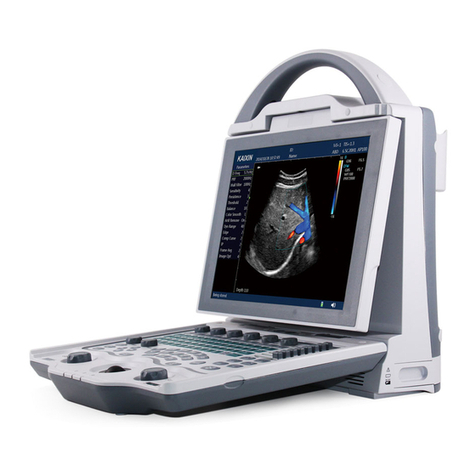
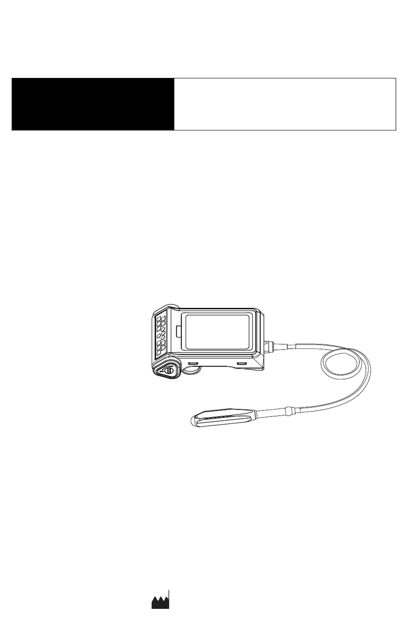
Kaixin DCU10 User manual

COLOR DOPPLER ULTRASOUND
DIAGNOSTIC SYSTEM
Operation Manual

Page 1 of 101
The following conventions are available throughout the manual to show special emphasised
information.
Sign
Meaning
Indicates a potentially hazardous situation which, if not avoided,
may result in death or serious injury
Indicates a potentially hazardous situation which, if not avoided,
may result in malfunction or damage of the system.
Indicates precautions or recommendations should be used when
operating the system.
[ ] Indicates on-screen objects such as menu items and prompt.
Boldfaced
Word Indicates eys on the control panel.

Page 2 of 101
Chapter 1 Safety......................................................................................................................................4
1.1 Safety Instructions ....................................................................................................................4
1.2 Principles of Using Acoustic Power ...........................................................................................6
1.3 Electromagnetic Compatibilities...............................................................................................9
Chapter 2 System Overview..................................................................................................................14
2.1 Intended Use ...........................................................................................................................14
2.2 System Configuration..............................................................................................................14
2.3 Physical Specifications ............................................................................................................15
2.4 Main Unit Overviews...............................................................................................................15
2.5 Peripherals Ports View............................................................................................................17
2.6 Power Supply Port...................................................................................................................17
2.7 Control Panel...........................................................................................................................18
2.8 Main Screen ............................................................................................................................21
2.9 Regular Examination Wor flow ..............................................................................................21
Chapter 3 Preparing an Exam ...............................................................................................................23
3.1 Positioning the system.........................................................................................................23
3.2 Booting the system .................................................................................................................23
3.3 Using the Battery ....................................................................................................................23
3.4 Booting/Standby/Powering off...............................................................................................24
3.5 Connecting the Probe .............................................................................................................25
3.6 Connecting the Peripherals.....................................................................................................26
Chapter 4 Presetting System.................................................................................................................27
4.1 Presetting the System .............................................................................................................27
4.2 Presetting the Probe/Exam.....................................................................................................29
4.3 Presetting the Measurements ................................................................................................30
4.4 Presetting the Annotations.....................................................................................................31
4.5 Presetting DICOM....................................................................................................................33
4.6 Presetting the Data Import/Export .........................................................................................34
4.7 System Information.................................................................................................................34
Chapter 5 Preparing for an Exam..........................................................................................................35
5.1 Registering a Patient ...............................................................................................................35
5.2 Selecting the Probe and Exam Type........................................................................................36
5.3 Ending the Exam .....................................................................................................................36
Chapter 6 Optimizing the Image...........................................................................................................37
6.1 B Mode....................................................................................................................................37
6.2 Color Doppler Flow Imaging (Color) Mode.............................................................................41
6.3 PDI Mode ................................................................................................................................45
6.4 M Mode...................................................................................................................................46
6.5 PW Mode ................................................................................................................................49
Chapter 7 Processing the Images..........................................................................................................54
7.1 Displaying the image...............................................................................................................54
7.2 Magnifying the Image .............................................................................................................55
7.3 Freezing the Image..................................................................................................................56
7.4 Viewing and Cropping the Cine ..............................................................................................56

Page 3 of 101
7.5 Annotating the Image .............................................................................................................56

Chapter 8 Measurements and Calculations..........................................................................................58
8.1 Measurement Screen and Keys...............................................................................................58
8.2 Measurement Menu ...............................................................................................................59
8.3 Measurement Error.................................................................................................................59
8.4 General Measurement............................................................................................................60
8.5 Specific Measurements and Calculations ...............................................................................67
Chapter 9 Report...................................................................................................................................78
9.1 Reviewing the Report..............................................................................................................78
9.2 Editing the Report ...................................................................................................................78
9.3 Printing the Report .................................................................................................................78
Chapter 10 Managing Images/Data......................................................................................................79
10.1 Saving the Image/Cine ..........................................................................................................79
10.2 Reviewing the Image/Cine ....................................................................................................79
10.3 Deleting the Image/Cine.......................................................................................................80
10.4 Printing the Image.................................................................................................................80
10.5 Saving Data............................................................................................................................81
Chapter 11 Probes and Biopsy ..............................................................................................................82
11.1 Probes ...................................................................................................................................82
11.2 Biopsy....................................................................................................................................85
Chapter 12 System Maintenance..........................................................................................................87
12.1 Cleaning the System..............................................................................................................87
12.2 Replacing the Fuse ................................................................................................................87
12.3 System Disposal ....................................................................................................................87
Chapter 13 Trouble shooting ................................................................................................................88
13.1 Chec .....................................................................................................................................88
13.2 Trouble shooting ...................................................................................................................88
Appendix A Specifications...................................................................................................................89
Appendix B Acoustic Output Data.....................................................................................................90

Page 4 of 101
Chapter 1 Safety
The operation safety is the most important concern of the designe. To ensure the safety and efficiency
of the system, the operator should read carefully about this chapter before using the system.
1.1 Safety Instructions
Read and understand all precautions in this manual before using the system.Keep this manual with the
system at all times. Periodically review the procedures for operation and safety precautions.
To maintain the performance and safety of the system, electric and mechanical safety inspections for the
system should be performed periodically by professional technicians in less than 6 months.
Do not use the system in the applications other than those listed in the intended use.Otherwise, it may
result in system damage or serious injury.
This equipment can only be used for diagnosis, cannot be used for treatment.
1.1.1 Electric Safety
Only qualified physicians or sonographers can perform ultrasound scanning on human body formedical
diagnosis.
The system can only be maintained by the person authorized or trained by the manufacturer.
The transducer is treated as the applied part.
Do not operate this system in an atmosphere containing flammable gases or liquids such
as anesthetic gases, hydrogen, and ethanol, because there is an danger of explosion.
Do not use this system at the same time with other equipment such as electric knife, defibrillator, and other
high-frequency therapy equipment. Otherwise, there is danger of electric shock.
keep the system dry, avoid beding transported to the field with a great temperature change to
prevent condensation or water droplets from resulting in short circuit.
Connect the earth conductor before powering on the system, Disconnect the grounding cable
after powering off the system. Otherwise, there is a danger of electric shock.
The AC power connector plug for the ultrasound system is a three-pin plug and should never be
adapted to any two-pin outlet. The AC power connector plug should be plugged into a hospital- grade
power outlet.
Do not place the multi-socket outlet on the floor.
Do not connect other devices to multi-socket outlet; otherwise, the rated output power may be
exceeded and failure may be resulted.
The multi-socket outlet can only be used to provide power to the recommended peripheral devices of this
system.
Select the qualified multi-socket outlet with protective grounding, and ensure its maximum output power
doesn't exceed the required one of this system.
If the non-medical electric equipment connected to the system is powered by the movable multi- socket

Page 5 of 101
outlet with the isolation transformer, you should connect the plug of the system to the
hospital-graded standard socket. Meanwhile, please consult the professional technician to ensure that
the connection meets the safety requirements.
The video printer should be connected to the cable provided by the manufacturer, otherwise, there is a
danger of electric shock.
It is recommended to connect this equipment to equipotential system. Use yellow and
greenequipotential grounding cables, one end is connected to position with symbol, and other
end is connected to equipotential system. Use of potential equalization conductor together with
areference to requirements of IEC 60601-1 for Medical Electrical System.
Do not pour any fluid onto the ultrasound system surfaces, as fluid seepage into the electrical circuitry may
cause excessive leakage current or system failure. If carelessly pour any water onto the system,
immediately stop using the ultrasound system and contact Service Representative immediately.
Only use the probes provided by the manufacturer. Otherwise, the ultrasound system cannot be
performed, and an accident such as a fire may result in the worst case.
The machine that are not serviced or maintained while in use with the patient.
Make sure the system is powered off and power cable is disconnected before cleaning the system.
Otherwise, an electric shock may happen.
Do not use this system in the strong electromagnetic field. Using the system in the improperenvironment may
result in malfunction or damage.
Only the peripherals and accessories (such as probes, peripherals or cables) provided or recommended by
the manufacturer can be used. Using other devices or accessories may degrade the system performance
and even cause an electrical shock.
1.1.2 Mechanical Safety
Please make sure that the system is powered off and the power cable and the relevant accessories are
disconnected before moving or transporting the system.
Place the system on a level desk.
The plug is used as disconnect to the mains supply, do not to position the machine so that it is
difficult to operate the disconnection device.
Do not place the system on a tilted plane with the angle larger than 10°. Otherwise, the systemwill
fall off to cause system damage or personal injury.
1.1.3 Accessories Safety
Use the probe carefully. If any part of the transducer surface is scratched, immediately stop using the probe.
Otherwise, there is a danger of electric shock.
After disinfecting the accessories, chemicals must be washed out from the accessories. Remaining

Page 6 of 101
residual chemicals or gases could not only result in damage to the accessories but also can
beharmful to human bodies.
You should use the legally marketed rubber latex (probe sheath) when performing trans-esophagus or
intracavitary exam, or biopsy exam. Please check the ingredient of the rubber latex on the
package before purchasing the rubber latex. Contact with natural rubber latex may cause a severe
anaphylactic reaction in persons sensitive to the natural latex protein. Refer to package labeling to check
latex content and FDA’s March 29,1991 Medical Alert on latex products
Do not use the footswitch in the operating room.
Only the trained physicians or sonographers can handle the biopsy needle guides under ultrasound guidance.
During the operation, the operator must observe proper needle insertion sequencing with the needle
guide in order to avoid undue discomforts, unnecessary risks or injuries to patient.
You should use the legally mar eted medical ultrasound couplants. Please chec the user instruction carefully
before using it, please manage and use the ultrasound couplants correctly to prevent it being polluted.
Disconnect the probe from the system after freezing an image or powering off the system.
Otherwise, the system or the probe could be damaged.
1.2 Principles of Using Acoustic Power
Perform ultrasound procedures prudently under the guidance of the ALARA (as low as reasonably
achievable) principle. Expose the patient to the lowest practical transmit power levels in the
shortest possible period to achieve a satisfactory diagnosis.
The operator should notice the effect of the heat on the patient body when the exam is performed around
the bones and the nearby soft tissues which can transform the ultrasound energy to heat energy.
Take special care to the fetal whose bones are growing.
1.2.1 Biological Safety
Diagnostic ultrasound is recognized as being safe, but the risk of biological effects exists when using it in high
exposure levels and long exposure times. Thus ultrasound should be used in a prudent manner to
provide medical benefit to the patient.
1.2.2 Mechanical and Thermal Indices
The ultrasound system displays two parts: thermal Index (TI) and Mechanical Index (MI). The MI/
TI value of the machine is real time displayed at the upper right corner, regarding how to change TI
display type, please choose: Preset → [System Preset] → [TI].
Meaning of MI/TI
Mechanical bioeffects are threshold phenomena that occur when a certain level of output is exceeded.
The threshold level varies with tissue type. The potential mechanical bioeffects varies with peak pressure
and ultrasound frequency. The higher the MI value, the greater the likelihood of mechanical bioeffects
occurring. There is no specific MI value theat means that amechanical effect is actually occurring. The MI
should be used as guide for implementing the ALARA principle.
The TI value informs the operator about the conditions that might lead to an increase in temperature at

Page 7 of 101
surface of the body, within the body tissue, or at the point of focus of the ultrasound beam on bone. That is,
the TI value informs the operator about the potential temperature rise in body tissue. It is an estimate of
temperature increase in body tissue with specific properties. The actual amount of an temperature rise is
influenced by factor such as tissue type, vascularity, mode of operation and others. The TI value should be
used as a guide for implementing the ALARA principle. Depending on the examination and type of tissue
involved, TI could be one of three types.
Soft Tissue Thermal Index (TIS) is used when imaging soft tissue only, it provides an estimate of potential
temperature rise in soft tissue.
Bone Thermal Index (TIB) is used when bone is near the focus of the image as in the third cropester OB
examination, it provides an estimate of potential temperature rise in the bone or adjacent soft tissue.
Cranial Bone hermal Index (TIC) is used when bone is near the skin surface as in transcranial examination,
it provides an estimate of potential temperature rise in the bone or adjacent soft tissue.
Precision of MI/TI
TI and MI values are displayed in real time on the screen. The operator should observe these index values
during examinations and ensure that exposure time and output values are maintained at minimum
amounts needed for effective diagnosis. The MI and TI precision is 0.1.
1.2.3 Acoustic utput Statement
1.2.3.1 The Influencing Factors of Acoustic Uncertainty
When estimating accuracy of displayed numerical values,many factors are considered:
● The probe changeability
● The system changeability
● Changeability and accuracy of measurement
● Possible operating conditions and testing numbers needed to obtain displayed result accuracy
of the
diagnostic system
● Whether the display accuracy depends on specific system combination, mode combination,
probe component
and launch mode combination, or all of above
● Algorithm accuracy of the system software used to calculate the MI/TI
● Approximation engineering method used in real time computation
1.2.3.2 Differences etween Actual and Displayed MI and TI
For many assumptions used in the process of measurement and calculation, actually they are
conservative.
For most organizations path, high estimate is made in the measurement and calculation
process of tissue
exposure intensity. For example, using attenuation coefficient 0.3dB cm
MHz1
much lower than the actual
human tissue attenuation coefficient, choosing conservative values
of tissue characteristic. Therefore, displayed
MI and TI values should be relative information for
reference, they serve to indicate to the operator whether a
particular setting of the system increases
or decreases the possibility of Thermal or Mechanical effect, used to
help the operator be careful to
use ultrasonic diagnostic system and follow the ALARA principle, these values
can not be equal to
actual values.
1.2.3.3 Uncertainty of Measurement
Sound pressure is the most basic data of sound field measurement, and other sound field parameters
can be
deduced from sound pressure, so when analysing measurement uncertainty, only take sound
pressure for
analysis and uncertainty of other parameters can be deduced from the sound pressure.

Page 8 of 101
Measurement uncertainty mainly include repeated measurement uncertainty and the system
uncertainty,
the system uncertainty is an order of magnitude higher than repeated measurement uncertainty, so the main
analysis is the system uncertainty. Mainly decided by the following factors:
1. The sensitivity of hydrophone:According to hydrophone calibration report provided by ONDA
company, the
maximum allowable error of sound pressure for hydrophone is plus or minus 12%;
2. Scope: according to agilent DSO6502A specifications, its effect on the sound pressure is plus or
minus 2%;
3. Temperature: effect of the thermocouple on sound pressure error is plus or minus 4%;
Above all uncertainty components are not related, synthetic standard uncertainty of sound pressure is:plus or
minus 13%.
1.2.4 perator Control Property
There are three types of operation control related to the generation of mechanical/thermal effect:
direct
control and indirect control, receiver control. Qualified operator should try to cut down the
acoustic output in the
premise of effective diagnostic images.
Direct control
The direct control of the acoustic output of this system is adjusting voltage size.But its maximum
acoustic output shouldn't be more than displayed acoustic output limit in any modes.
Indirect control
The controls that indirectly affect output are many imaging parameters. These are operating modes,
frequency,focal point number/position, image depth and pulse repetition frequency (PRF)(By adjusting
the [Scale] of the toolbar).
The operating mode determines whether the ultrasound beam is scanning or non-scanning. Thermal
effect is closely connected to M Mode, PW Doppler and Color Mode.
Acoustic attenuation of tissue is directly related to transducer frequency.
The focal point number and position is related to active aperture of transducer and beam width.
For the pulse repetition frequency( PRF)(By adjusting the [Scale] of the toolbar), the higher the PRF,
the more acoustic output power increased over a period of time.
The receiver control
The receiver control does not affect the acoustic output, including gain, dynamic range, and image
processing, etc. Therefore, in the image optimization, should adjust the receiver control to optimize
images firstly, the second are through direct control and indirect control.
When acquiring images, it is recommended to use the default (or as low as possible) acoustic output
location, and use the gain control to compensate. The default setting is commonly 70% of maximum
allowed acoustic output value, which will not cause harm to the operator, and for the probe is the most
effective value
1.2.5 Acoustic Power Settings
The ultrasound system has been preset the parameters for each exam mode with different probes
before shipment. When the ultrasound system is powered on, a new patient is created or the application
mode is changed, the system will retrieve the default settings. You can also reset the parameters.
1.2.6 ALARA
It is required to practice ALARA when using ultrasound energy. Practicing ALARA ensures that the total

Page 9 of 101
energy level is controlled below a low level at which bioeffects are not generated while diagnostic
information is being accumulated. The total energy is controlled by output intensity and total radiation time.
The output intensity necessary for examinations differs depending on the patient and clinical case.
Not all examinations can be performed with an extremely low level of acoustic energy.Controlling the
acoustic level at an extremely low level leads to low-quality images or insufficient Doppler signals, adversely
affecting the reliability of the diagnosis. However,increasing the acoustic power more than necessary
does always contribute to an increase in quality of information required for diagnosis, rather increasing the
ris of generating bioeffects.
The operator must ta e responsibility for the safety of patients.
1.3 Electromagnetic Compati ilities
Electromagnetic compatibilities are the abilities of the system or equipment to operate
normally in the electromagnetic environment and not to radiate any electromagnetic interruptions to any
other objects which are in the same environment.
This system is designed in accordance with the current EMC requirement. And the
ultrasound image will degrade instantly if the system is used in the electromagnetic field
environment. If the degradation of the image is found, it is recommended to inspect the
operation environment to confirm the radiation source.
1.3.1 Electromagnetic Radiation
This system is applicable for the following environment. You should use this system
under the suggested environment.
Emission Test Compliance Electromagnetic Environment and Guidance
RF emission
CISPR 11
Group 1
ClassA
Harmonic
emission IEC
61000-3-2
Class A
Voltage fluctuations/
flicker emissions IEC
61000-3-3
Complies
The equipment use RF energy only for its internal function.
Therefore, its RF emission is very low and not li ely to cause
any interference to nearby electronic equipment.
1.3.2 Electromagnetic Immunity
Immunity Test IEC 60601 Test Level Compliance Level Electromagnetic
Environment and
Guidance
Electrostatic
discharge (ESD)
IEC 61000-4-2
±6 V Contact
±8 V Air
±6±6 V Contact
±8kV Air
Floors should be wood,
concrete or ceramic tile. If
floors are covered with
synthetic material, the
relative humidity should be
at least 30%.

Page 10 of 101
Electrical fast transient
burst IEC 61000-4-4
±2 kV for power supply
lines, ±1 kV for input
output lines
±2 kV for power supply
lines, ±1 kV for input
output lines
Mains power quality should
be that of a typical
commercial or hospital
environment.
Surge
IEC 61000-4-5
±1kV line to line
±2kV line to earth
±1kV line to line
±2kV line to earth
Mains power quality
should be that of a typical
commercial or hospital
environment.
Voltage dips and Short
interruptions IEC
61000-4-11
< 5%U
T
(>95% dip in U
T
)
for 0.5 period;
40%U
T
(60% dip in U
T
)
for5 period;
70%U
T
(30% dip in U
T
)
for25 period)
< 5%U
T
(>95% dip in U
T
)
for 5 seconds
< 5%U
T
(>95% dip in U
T
)
for 0.5 period;
40%U
T
(60% dip in U
T
)
for5 period;
70%U
T
(30% dip in U
T
)
for25 period)
< 5%U
T
(>95% dip in U
T
)
for 5 seconds
Mains power quality should
be that of a typical
commercial or hospital
environment. If the user of
the equipment requires
contained operation during
power mains interruptions,
it is recommended for the
equipment to be powered
from an uninterruptible
power supply.
Power frequency(50/60
Hz)
IEC 61000-4-8
3 A/m
3 A/m
Power frequency of
magnetic fields should be
at leveled characteristic
of a typical location in a
typical commercial or
hospital environment.
NOTE: U
T
is the a.c. mains voltage prior to application of the test level.
Immunity
Test
IEC 60601
Test Level
Compliance
Level
Electromagnetic Environment and
Guidance
Conducted RF
IEC 61000-4-6
3Vrms
150kHz-80
MHz
1 Vrms
Radiated RF
IEC 61000-4-3
3V/m
80 MHz-2.5GHz
3 Vrms
Portable and mobile RF communications
equipment should be used no closer to any part
of the EQUIPMENT, including cables, than the
recommended separation distance calculated form
the equation applicable to the frequency of the
transmitter.
Recommended separation distance:
Where P is the maximum output power rating of
the transmitter in watts (W) according to the
transmitter manufacturer and d is the
recommended separation distance in meters (m).
Field strengths from fixed RF transmitters, as
determined by an electromagnetic site survey,
"should be less than the compliance level in

Page 11 of 101
each frequency range." Interference may occur
in the vicinity of equipment marked with the
following symbol:
NOTE 1: At 80 MHz and 800MHz, the higher frequency range applies.
NOTE 2: These guidelines may not apply in all situations. Electromagnetic propagation is affected by absorption
and reflection from structures, objects and people.
Field strengths from fixed transmitters, such as base stations for radio (cellular/cordless) telephones and land
mobile radios, amateur radio, AM and FM radio broadcast and TV broadcast cannot be predicted theoretically
with accuracy. To access the electromagnetic environment due to fixed RF transmitters, and electromagnetic site
survey should be considered. If the measured filed strength in the location in which the EQUIPMENT is used
exceeds the applicable RF compliance level above, the EQUIPMENT should be observed to verify normal
operation. If abnormal performance is observed, additional measures may be necessary, such as re-orienting or
relocationing the EQUIPMENT.
Over the frequency range 150kHz to 80MHz, field strengths should be less than 3 V/m.
1.3.3 Recommended Minimum Distance Between Device and Mobile RF Equipment
The equipment is intended for use in an electromagnetic environment in which radiated RF disturbance
are controlled. The customer or the user of the equipment can help prevent electromagnetic interference by
maintaining a minimum distance between portable and mobile RF communications equipment (transmitters)
and the equipment as recommended below, according to the maximum output power of the communications
equipment.
Separation distance according to frequency of transmitter
(m)
Rated Maximum
Output Power
of
Transmitter
(W) 150 kHz to 80 MHz
80 MHz to 800 MHz
800 MHz to 2.5 GHz
0.01 0.12 0.12 0.23
0.1 0.38 0.38 0.73
1 1.2 1.2 2.3
10 3.8 3.8 7.3
100 12 12 23
For transmitters rated at a maximum output power not listed above, the recommended separation
distance d in meters (m) can be estimated using the equation applicable to the frequency of the
transmitter, where P is the maximum output power rating of the transmitter in watts (W) according to the
transmitter manufacturer.
NOTE 1: At 80 MHz and 800 MHz, the separation distance for the higher frequency range applies.
NOTE 2: These guidelines may not apply in all situations. Electromagnetic propagation is affected by
absorption and reflection from structures, objects and people.

Page 12 of 101
If the system has generated the interference (confirmed by powering on and off the system), you or
the qualified service personnel should solve the problem by following the steps as below:
Reposition the affected system.
Place this system further away from the affected system.
Supply power to this system in other ways other than the way used currently.
Contact the manufacturer as soon as possible.
1.3.4 Signs and Meaning
Sign Meaning
Caution! Please consult the accompanying document.
Warning, danger of electric shock!
Type BF applied part
Disconnect (the mains supply)
Connect (the mains supply)
Power on/standby button
Footswitch
Cable connecting the video printer
Protective earth
Serial port
Equipotentiality
Alternating current
Degree of IP protection
Non-ionizing electromagnetic radiation
Manufacturer
Date of manufacturer

Page 13 of 101
Sign
Meaning
Consult the user manual
Network port
USB port
Video output
Fragile
Keep dry
Keep this way upward
Atmospheric pressure range of the transportation
Relative humidity range of the transportation
Ambient temperature rang of the transportation
Maximum of 4 layers allowed for the system
Do not roll.
Keep in shade
Indicates the presence of hazardous substance (s) above the maximum concentration value(s) as
set in SJ/T11364-2006. "10" indicates the number of years during which the hazardous
substance(s) will not leak or mutate so that the use of this product will not result in ay severe
environmental pollution, bodily injury, or damage to any assets.
Serial number
Unrecyclable
Authorized EU Representative

Page 14 of 101
Chapter 2 System verview
You should familiar with the components, physical specification, operation of the eys and buttons,
the general wor flow before using this system.
2.1 Intended Use
The ultrasound system is intended for animal ultrasound diagnosis, can be applied to
Cannine,Feline,Equine,Bovine, Ovine and Other animals. The application parts are as follows: abdomen,
obstetrics, cardiac, smallparts, vascular.
vascular, pediatrics, thyroid, breast, carotid, idney.
Contraindication: The ultrasound system is not intended for ophthalmic use or any use causing
the acoustic beam to pass through the eye.
2.2 System Configuration
2.2.1 Standard Configuration
▆ Main Unit
▆ Accessories:
Micro Convex Array Transducer(6C15C), Linear Array Transducer(7L4C)
Operation Manual
Power Supply Cable
2.2.2 ptions
2.2.2.1 Optional Pro es
Pro e Name
Pro e Types Applications
7L4C Linear Array Transducer SmallPart, Vascular
3C6C Convex Array Transducer Abdomen,Obstetrics, Cardiac
6I7C Rectal Transducer Obstetrics
6C15C Micro Convex Array Transducer Abdomen, Obstetrics,Cardiac
2.2.2.2 Optional accessories
NO. Accessories
1 Footswitch
2
Graphic printer
3
Blackwhite video printer
4 Color video printer
5
Biopsy bracket
6
Luggage Case

Page 15 of 101
7
Mobile Trolley
8
USB flash disk
9
USB Extension Line
2.3 Physical Specifications
Monitor: 15'' LED screen
Dimension: 400mm (L) x 394mm (H) x 172 (D)
Weight: approximately 7.5 g
2.4 Main Unit Overviews
Figure 2-1 Main Unit Overview

Page 16 of 101
2.4.1 Side View
Figure 2-2 Side View
2.4.2 Rear View
Figure 2-3 Rear View

Page 17 of 101
2.5 Peripherals Ports View
Figure 2-4 Peripherals Ports
No. Name Function
1
VGA port
Used for connecting the video equipment generating VGA
signals, such as monitor and projector.
2 Serial port Used for connecting the debugging cable and exporting
the debugging information for after-sales servicing.
3 Footswitch port Used for connecting the footswitch.
4
Video output
port
Used for connecting the video equipment generating the
composite video signals, such as video printer.
5 Networ port Used for connecting DICOM server or networ .
6 USB port
Used for connecting the usb equipment,such as u disk and
usb printer.
2.6 Power Supply Port
Figure 2-5 Power Supply Port
No. Name Function
1 Equipotentiality
terminal
Used for balancing the protective earth potentials
between this system and other electrical equipment.
2 AC power input
port Used for connecting the AC power supply.

Page 18 of 101
2.7 Control Panel
Sign Name Functions
Indicators Area
Power
indicator
The indicator lights on when the system is powered by the
alternative current.
Battery
capacity
indicator
The indicator lights on the when the system is powered by the
battery.
● The indicator flashes when the battery capacity is
lower than 30%.
● The indicator lights on solid when the battery is in full
capacity.
Battery charge
indicator
The indicator lights on when the battery is charged and
lights off when the battery is fully charged.
Keyboard Area
ESC ESC Key 1. When dialog is open, press it to close the opendialog.
2. When preset submenu is displayed, press it to exit
preset submenu and return to previous menu
3. When preset primary menu is displayed, press it to exit
preset primary menu.
Help Help Key Press it to display help information
Report Report ey Press it to enter the report screen.

Page 19 of 101
Station Station ey Press it ot enter the wor station screen.
Preset Preset ey Press it to enter the system setting screen.
Save IP Save current image
parameters ey
Press it to save the parameters setting of the current
imaging mode.
Reset IP restore the preset
image parameters ey
Press it to restore the parameters setting of the current
imaging mode from preset.
Biopsy Biopsy ey Press it to activate the biopsy function.
Lito Lito ey Press it to activate the lito function.
Menu Menu ey Press it to hide/display the menu function.
Body Mar Body mar ey Press it to enter/exit the body mar status.
Comment Text
annotation ey
Press it to enter/exit the text annotation status.
Arrow Arrow
annotation key Press it to enter/exit the arrow annotation status.
Clear Clear ey
Press it to remove all the annotations and measurements from
the screen.
Left/right ey
● Press it to adjust the steer angle in PW \ Color/PDI status.
● Press it to move the cursor left or right in other status.
Up/down ey
Press it to adjust the volume of the frequency spectrum
in the real time PW mode.
Ctrl +
blan
Typewriting
selection ey
Press the combined eys to select the desired typewriting.
- Other eys Achieve the functions similar with the eys on the eyboard
of the computer.
Function Keys
Power ey
Press it to power on or off the system or to
enable standby mode.
TGC slide pot
● There are 8 TGC slide pot.
● Move it to adjust the gain of the specified depth.
Patient Patient ey Press it to enter the patient information screen to create or
edit the patient information.
Probe/
Exam
Probe and exam mode
selection ey
Press it to enter the probe and exam selection mode to
select the probe and the application part.
Review Review ey Press it to enter the file review screen.
End Exam End the exam Key Press it to end the exam of the current patient.
B B mode ey Press it to enter the B mode.
Other manuals for DCU10
1
Table of contents
Other Kaixin Diagnostic Equipment manuals