Pro-tec PRS 500 F User manual

PROTEC GmbH & Co. KG
In den Dorfwiesen 14, 71720 Oberstenfeld, Germany
Version:5.0
Issued: 2020-11-12
Subject to alterations
PRS 500 F
Basic diagnostic X-ra s stem
Model/ID: 7067-9-8050
Instructions for use
Ident. Nr. 5067-0-8002
PRS 500 F in analogue base
configuration

NOTE
All sheets of this document contain proprietary and confidential information of
PROTEC GmbH & Co. KG and is intended for exclusive use by current PROTEC GmbH
& Co. KG customers. Copying, disclosure to other or other use is prohibited without
the express written authorization of PROTEC´s law department. Report any
violations of this requirement to PROTEC GmbH & Co. KG.
© 201 PROTEC GmbH & Co. KG, Oberstenfeld
These accompanying documents were created and distributed by the documentation department.
Comments and questions about the documentation, please contact:
PROTEC GmbH & Co. KG
In den Dorfwiesen 14 | 71720 Oberstenfeld
Deutschland
Phone: (+ 49) 7062 – 92 55 0
Fax: (+ 49) 7062 – 92 55 60
E-Mail: protec@protec-med.com
Internet: www.protec-med.com

PRS 500 F
Instructions for use
5067
-
0
-
8
002
PROTEC GmbH & Co. KG, In den Dorfwiesen 14, 71720 Oberstenfeld, Germany
3
von
41
Table of contents
Page
Table of contents ........................................................................................................................... 3
Document Effectivit .................................................................................................................... 6
General Notes ................................................................................................................................ 7
Mechanical – Electric Warning .................................................................................................... 7
Radiation Warning ........................................................................................................................ 7
To the User ..................................................................................................................................... 8
1
Product description ............................................................................................................ 9
1.1 Introduction .........................................................................................................................................................................................
1.2 Description............................................................................................................................................................................................
1.2.1 Equipment components .................................................................................................................................................
1.2.2 Installation ................................................................................................................................................................................
1.2.2.1 Floor capacity ................................................................................................................................................................ 10
1.3 Product specific characteristics ............................................................................................................................................. 10
1.3.1 Variable height radiographic table ...................................................................................................................... 10
1.3.2 Floor railed X-ray system tube support ............................................................................................................... 10
1.3.3 VerticalX-ray system image receptor stand ...................................................................................................... 10
1.4 Intended use ..................................................................................................................................................................................... 10
1.5 Indication and Contraindication .......................................................................................................................................... 11
1.5.1 Indications ............................................................................................................................................................................. 11
1.5.2 Contra indications ............................................................................................................................................................. 11
1.6 Intended user group .................................................................................................................................................................... 11
1.7 Conformity ......................................................................................................................................................................................... 12
2
Safet Instructions ............................................................................................................ 13
2.1 General safety notice ................................................................................................................................................................... 15
2.1.1 Requirements for operation ....................................................................................................................................... 15
2.1.2 Operating of the radiographic system ................................................................................................................. 15
2.1.3 Operating type .................................................................................................................................................................... 15
2.1.4 Operating personnel ....................................................................................................................................................... 15
2.1.5 Pinching and Collision Hazards ................................................................................................................................ 16
2.1.6 Explosion protection ....................................................................................................................................................... 16
2.1.7 Radiation protection ....................................................................................................................................................... 16
2.1.8 Ventilation .............................................................................................................................................................................. 16
2.1. Interaction with external devices ............................................................................................................................ 16
2.1.10 Electromagnetic Environment and the influence of devices ................................................................ 17
3
Control elements and device displa s ........................................................................... 18
3.1 Control elements and device displays PROGNOST F .............................................................................................. 18
3.2 Control elements and device displays PROGNOST SH ........................................................................................... 18
3.2.1 Operating unit PROGNOST SH, Standard .............................. Fehler! Textmarke nicht definiert.
3.2.2 Operating unit PROGNOST SH, TOUCH .................................. Fehler! Textmarke nicht definiert.
3.3 Control elements and device displays collimator ..................................................................................................... 21
3.4 Control elements and device displays of X-ray tube ............................................................................................... 21
3.5 Control elements and device displays of X-ray generator ................................................................................... 21
3.6 Control elements of Bucky, Grid entity ............................................................................................................................. 21
3.7 Control elements and device displays of verticalX-ray system image receptor stand PROVERT . 22
3.7.1 Vertical carriage .................................................................................................................................................................. 22
3.8 Control elements and device displays of RAPIXX system ..................................................................................... 22
3. Control elements and device displays of CONAXX 2 .............................................................................................. 22
4
Handling / Operation ........................................................................................................ 23
4.1 Operation with the radiographic system ........................................................................................................................ 23
4.1.1 Operation at the X-ray system table ...................................................................................................................... 23
4.1.1.1 Position of patients on the tabletop ............................................................................................................... 23
4.1.1.2 Setting the X-ray unit on the mid moving Bucky, Grid entity ......................................................... 23

PRS 500 F
Instructions for use
5067
-
0
-
8
002
PROTEC GmbH & Co. KG, In den Dorfwiesen 14, 71720 Oberstenfeld, Germany
4
von
41
4.1.1.3 Inserting a cassette into the cassette tray .................................................................................................... 23
4.1.1.4 Adjusting the focus-film distance (FFD) ........................................................................................................ 23
4.1.1.5 Adjusting the light resp. X-ray field .................................................................................................................. 23
4.1.1.6 Exposure preparation / exposure release .................................................................................................... 23
4.1.1.7 Overtable exposures ................................................................................................................................................. 23
4.1.2 Operation at verticalX-ray system image receptor stand PROVERT ................................................... 25
4.1.2.1 Adjustment of the X-ray unit to the mid of a cassette or Bucky/Grid entity of aX-ray
system image receptor stand (vertical center beam) ................................................................................................. 25
4.1.2.2 Adjustment of the source to image-receptor distance (SID) ........................................................... 25
4.1.2.3 Adjustment of the light-/ radiation field....................................................................................................... 25
4.1.2.4 Exposure preparation/ release ............................................................................................................................ 25
4.2 Operation X-ray system table PROGNOST F.................................................................................................................. 25
4.3 Operation collimator ................................................................................................................................................................... 25
4.4 Operation X-ray tube ................................................................................................................................................................... 25
4.5 Operation X-ray generator ....................................................................................................................................................... 26
4.6 Operation Bucky, Grid entity ................................................................................................................................................... 26
4.7 Operation verticalX-ray system image receptor stand PROVERT ..................................................................... 26
4.8 Operation RAPIXX system......................................................................................................................................................... 26
4. Operation Software ...................................................................................................................................................................... 26
4.10 Function of the PRS 500 F......................................................................................................................................................... 26
4.10.1 Switching On/Off the PRS 500 F .............................................................................................................................. 26
4.10.2 Dosimetric Calibration (only for PROVARIO HF) ............................................................................................. 26
4.11 Exposure automatic ..................................................................................................................................................................... 27
5
Safet and Maintenance ................................................................................................... 28
5.1 Introduction ...................................................................................................................................................................................... 28
5.2 Cleaning and disinfection ......................................................................................................................................................... 28
5.2.1 Cleaning .................................................................................................................................................................................. 28
5.2.2 Disinfection ........................................................................................................................................................................... 28
5.3 Check-up and maintenance ................................................................................................................................................... 2
5.3.1 Daily Controls (prior to or during the unit operation) ................................................................................ 2
5.3.2 Regular controls ................................................................................................................................................................. 2
5.3.3 Only original spare parts are to be used in situations requiring component replacement
Maintenance ................................................................................................................................................................................................ 2
5.3.4 Warranty .................................................................................................................................................................................. 2
5.3.5 Product life time ................................................................................................................................................................. 2
5.3.6 Further Information ......................................................................................................................................................... 2
5.3.7 Applied Parts and parts which get handled like an application part ................................................ 30
5.3.8 Disposal ................................................................................................................................................................................... 30
6
Electrical data ..................................................................................................................... 31
6.1 Electromagnetic Compatibility (EMC) after EN 60601-1-2 ................................................................................... 32
6.1.1 Guidelines and Manufacturers declaration – electromagnetic interference (non-life
supporting device) ................................................................................................................................................................................... 32
7
Technical Data .................................................................................................................... 33
7.1 Dimensions ........................................................................................................................................................................................ 33
7.2 X-ray system table PROGNOST F .......................................................................................................................................... 35
7.3 Bucky, Grid entity ........................................................................................................................................................................... 35
7.4 X-ray system tube support, floor stand ............................................................................................................................ 35
7.5 Vertical X-ray system image receptor stand .................................................................................................................. 35
7.6 Attenuation Equivalent .............................................................................................................................................................. 36
7.6.1 Protection Art and Protection Class ....................................................................................................................... 36
7.7 Automatic cutoff dose ................................................................................................................................................................ 36
7.7.1 Analogue System .............................................................................................................................................................. 36
7.7.2 Digital System ...................................................................................................................................................................... 36
7.8 Environmental ................................................................................................................................................................................. 36
7.8.1 Environmental conditions during operation ................................................................................................... 36
7.8.2 Environmental Conditions for Shipping and Storage ................................................................................ 36
8
Description of s mbols, labels and abbreviations ....................................................... 37

PRS 500 F
Instructions for use
5067
-
0
-
8
002
PROTEC GmbH & Co. KG, In den Dorfwiesen 14, 71720 Oberstenfeld, Germany
5
von
41
8.1 Symbols ............................................................................................................................................................................................... 37
8.2 Identification label......................................................................................................................................................................... 38
8.3 Labels .................................................................................................................................................................................................... 3
8.4 Position symbols and labels .................................................................................................................................................... 40

PRS 500 F
Instructions for use
5067
-
0
-
8
002
PROTEC GmbH & Co. KG, In den Dorfwiesen 14, 71720 Oberstenfeld, Germany
6
von
41
NOTE
The information
contained in this document conforms to the configuration of the
equipment as of the date of manufacture. Revisions to the equipment subsequent
to the date of manufacture will be addressed in service updates distributed to the
PROTEC Technical Service Organization.
Document Effectivit
Revision No. Date List of effective pages Comments
1.0 201 -05-14 all New created, replaces
document 5087-0-0002
2.0 201 -07-31 Cap. 1.2, 1.7, 6.1.1, 8.1, 8.2,
8.4
GMDN terms updated
Changed optional
accessories and images
dimension
EMC tables removed
Symbols added
Identification label
updated
3.0 2020-06-1 Cap. 1.2.2.1, 1.3.2, 3.2, 7.4 Telescopic arm added
4.0 2020-08-11 Front page, Cap. 5.3.3 Maintenance updated
5.0 2020-11-12 Cap. 1.2.1; Cap.6; Cap. 3.1.1;
Cap. 3.1.2; Cap. 4.1.1.8
New generators,
Rotatable X-ray column
added

PRS 500 F
Instructions for use
5067
-
0
-
8
002
PROTEC GmbH & Co. KG, In den Dorfwiesen 14, 71720 Oberstenfeld, Germany
7
von
41
General Notes
WARNING!
No changes of the ME device!
Mechanical – Electric Warning
WARNING!
All of the movable assemblies and parts of this equipment should be operated
with care and routinel inspected in accordance with the manufacturer's
recommendations contained in the equipment Accompan ing Documents.
Maintenance and service is onl to be performed b Customers authorized b
PROTEC GmbH & Co. KG.
Live electrical terminals are deadl .
Do not remove flexible high-tension cables from X-ra tube housing or high-
tension generator and/or access covers from X-ra generator.
For all components of the equipment protective earthing means must be
provided in compliance with the national regulations.
Failure to compl with the foregoing ma result in serious or fatal bodil
injuries to the operator or those in the area.
Radiation Warning
WARING!
The component of the equipment described within this Document is part of a
s stem for the intended generation of X-ra s for medical diagnosis.
X-ra s generate a potential risk for both patients and operators.
For this reason, the application of X-ra s for a given medical purpose must
aim at the minimization of radiation exposition to an persons. Those persons
responsible for the application must have the specific knowledge according
to legal requirements and regulations and must establish safe exposure
procedures for these kinds of s stems. Those persons, responsible for the
planning and installation of this equipment, must observe the national
regulations.
The s stem causes different ionising radiation. The purpose is to create
characteristic X-ra radiation. The intensit depends on the adjusted values of
voltage, current and time. The radiation comes orthogonal out of the X-ra
tube and is limited b the collimator.

PRS 500 F
Instructions for use
5067
-
0
-
8
002
PROTEC GmbH & Co. KG, In den Dorfwiesen 14, 71720 Oberstenfeld, Germany
8
von
41
To the User
NOTE
The user of this Document is directed to read and carefully review the instructions,
warnings and cautions contained herein prior to beginning operation, installation or
service activities.
While you may have previously operated equipment similar to that described in this
Document, changes in design, manufacture or procedure may have occurred which
significantly affect the present operation.
Although the product was subject to a risk analysis and the design corresponds to
the current state of the art, residual risk will remain in clinical use. These are
displayed in the following user manual by application limitations, contraindications,
warnings and precautions.
The installation and service of equipment described herein is to be performed by
authorized, qualified PROTEC GmbH & Co. KG Customers.
Assemblers and other Customers not employed by nor directly affiliated with
PROTEC GmbH & Co. KG technical services are directed to contact the local
PROTEC GmbH & Co. KG office before attempting installation or service
procedures.
For Installations and service procedures it is necessary to read the “technical
description“ of the product and to observe any containing point in it.
NOTE
The usage of the product in combination with accessories which aren’t authorized
by PROTEC is forbidden.

PRS 500 F
Instructions for use
5067
-
0
-
8
002
PROTEC GmbH & Co. KG, In den Dorfwiesen 14, 71720 Oberstenfeld, Germany
von
41
1
Product description
1.1 Introduction
This user manual describes the special features and operational aspects of the PRS 500 F, knowledge of
which are required for efficient and effective use of the radiographic system.
Prior to working with the PRS 500 F, it is required that the user reads the Safety Notes as well as the
chapter regarding operation.
1.2 Description
1.2.1 Equipment components
The PRS 500 consists of the following components:
•Stationary patient positioning table with floating table top
•Floor railed X-ray system tube support, floor stand with control arm,
•Bucky or Grid entity,
•VerticalX-ray system image receptor stand,
•X-ray Generator, PROVARIO HF-, VENUS-, CMP- or RFX series
•X-ray tube assembly with housing,
•Collimator
Optional components
•Anti-scatter Grid
•3-field measuring chamber,
•Dose area product meter system and
•Different direct X-ray-systems (RAPIXX-Serial)
(consisting of DR-detector, Interface Box, and Software)
•Software CONAXX 2
Optional Accessories
The PRS 500 F can be equipment or customized with the following accessories:
•Patient extending handle
•Compression band
•Mattress
•Short hand grip
•Short hand grip adjustable
•Long hand grip
•Strain relief cable hoseX-ray system image receptor stand
•Lateral Detector holder
Only with rotatable X-Ray column PROGNOST SH
Accessories which can influence the EMC-Condition
•Network cable (note the max. length in the documents)
•RAPIXX Data-Cable (note the max. length in the documents)
•WLAN-Router (only use devices that has an authorization by PROTEC)
•…
1.2.2 Installation
See separate “Installation manual” PRS 500 F.
Contact information of persons which are qualified to make installations are requestable at:
PROTEC GmbH & Co. KG
In den Dorfwiesen 14 | 71720 Oberstenfeld
Telephone: +4 (0) 7062 – 2 55 0
Fax: +4 (0) 7062 – 2 55 60
E-Mail: protec@protec-med.com
Internet: www.protec-med.com

PRS 500 F
Instructions for use
5067
-
0
-
8
002
PROTEC GmbH & Co. KG, In den Dorfwiesen 14, 71720 Oberstenfeld, Germany
10
von
41
1.2.2.1 Floor capacit
NOTE
T
he
radiographic
system is primarily made of metal pieces. This has a main role in
the weight of the device.
The radiographic system PRS 500 F has a weight of 784kg (incl. Generator),
option: telescopic arm 30kg (additionally).
Every technician is obliged to check the ground load. Also double bottoms and
hollow floors have to be taken into account.
1.3 Product specific characteristics
1.3.1 Radiographic table
•Floating table top
•Table top colour – white
•Motor activated table top brake for effortless patient positioning
•A low (optimized) distance between the table top surface and the film (detector) surface
•Large adjustment range of the table top for position of the patient
•Reliable construction
•Lateral rails of the table top prepared to accept a number of table accessories
•Prepared for the installation of a Bucky with anti-scatter grid and 3-field measuring chamber
intended for the use with automatic exposure control
•Useable for variable cassette/detector sizes. Formats from 13 cm x 18 cm (5” x 7”) to 43 cm x 43
cm (17” x 17”), depending on analog or digital use
1.3.2 Floor railed X-ra s stem tube support
•Ceiling-free column stand intended for use within rooms with a ceiling height of at least 2.3
meters
•Wide range of application
•Small wall distance allows good space utilization
•Control elements within the command arm well placed and easy to activate
•Reproducible positioning of the X-ray tube assembly (positions resulting from rotation around
the axis of the carrying arm) through angle indicator
•Vertical range of travel of the focus height from 2 .4 cm up to 188.2 cm during horizontal
beam projection
•Electromagnetic brakes for the longitudinal movement of the column stand, the vertical
movements of the carrying arm, the rotational movements of the X-ray tube assembly around
the axis of the carrying arm +/-180° with integrated latching every 0° as well as transversal
movement of the carrying arm +230mm (optional).
•Integrated safety connector for automatically centering the X-ray tube assembly and the Bucky
in the longitudinal direction
1.3.3 Vertical X-ra s stem image receptor stand
•Space saving with minimal footprint
•Wall – floor mounting of floor mounting
•cassette loading from the right or left side (specified at installation)
•Useable for variable cassette/detector sizes. Formats from 13 cm x 18 cm (5” x 7”) to 43 cm x 43
cm (17” x 17”), depending on analog or digital use
1.4 Intended use
The general-purpose diagnostic radiographic systems of the PRS 500-series are intended for various
routine applications in planar X-ray imaging in human medicine.
They are stationary systems that can be used both for analogue and digital imaging.

PRS 500 F
Instructions for use
5067
-
0
-
8
002
PROTEC GmbH & Co. KG, In den Dorfwiesen 14, 71720 Oberstenfeld, Germany
11
von
41
NOTE
At the acceptance test a 25mm Aluminium / ,5% purity can be used as a
phantom for a patient equivalent.
The acceptance test has to be made in accordance to the local laws and directives.
Only Special trained People are allowed to do this.
1.5 Indication and Contraindication
1.5.1 Indications
Justification of medical exposures
According to §83 of the German radiation protection law (StrlSchG), an X-ray examination is only
justified if the patients benefit from x-ray diagnostics outweighs the radiation risk. The examination
method, means the conventional X-ray with the PRS 500 system, must be suitable to answer the
diagnostic question and no other more suitable alternative method is available.
Accordingly, it is also described by the International Atomic Energy Agency (IAEA) in the document
Radiation Protection and Safety of Radiation Sources: International Basic Safety Standards (Requirement 37:
Justification of medical exposures). It also refers to the need to consider national or international
guidelines for the justification of a medical exposure.
A complete list of indications is unrealisable for conventional radiography, because the spectrum of
conventional X-rays is very diverse and can vary in the course of medical-technical progress.
Some examples of indications for an X-ray examination may be:
•For the diagnosis of a bone fracture or bony injuries of the skeletal system or pathological
changes of hard tissues.
•To control the bone setting.
•For the diagnosis of luxations and ligament ruptures of the locomotor system.
•For the diagnosis of degenerative, inflammatory, traumatic and tumorous diseases and
changes of the locomotor system.
•For diagnostic of malformations and malalignments of the skeletal system.
•For the diagnosis of thoracic and pulmonary symptoms (thorax exposures)
•For the diagnosis of sclerotherapy.
•For the diagnosis of inflammatory and expansive processes of the mucosa, cranial bones and
paranasal extension.
•For the diagnosis of the abdomen (e.g. acute abdomen, plain abdominal radiography,
urethrogram, cystogram).
1.5.2 Contra indications
There are no absolute contraindications for conventional X-rays.
But it is not allowed to make any exposures on humans when they are not medically indicated (see
Justification of medical exposures, chapter 1.5.1 Indication).
For pregnant women and children it is important to consider if the exposure is really necessary. It
should be avoided if possible.
1.6 Intended user group
The radiographic system PRS 500 F is exclusively designated for use by professional who are trained, in
accordance with the corresponding national regulations, in the use of diagnostic X-Ry equipment and
its proper intended use in connection with other medical devices, objects and accessories.
Suitable users could include the following: Radiologist, radiology assistants, radiology technicians,
doctors and other medically trained personnel.

PRS 500 F
Instructions for use
5067
-
0
-
8
002
PROTEC GmbH & Co. KG, In den Dorfwiesen 14, 71720 Oberstenfeld, Germany
12
von
41
1.7 Conformit
This product is in conformity with the requirements of the European Community
Medical Device Directive 3/42/EEC from 06/14/1 3 including all current
revision standards.
The declaration of conformity is available directly from PROTEC:
PROTEC GmbH & Co. KG
In den Dorfwiesen 14 | 71720 Oberstenfeld
Telephone: +4 (0) 7062 – 2 55 0
Fax: +4 (0) 7062 – 2 55 60
E-Mail: protec@protec-med.com
Internet: www.protec-med.com
PRS 500 F
Instructions for use
5067
-
0
-
8
002
PROTEC GmbH & Co. KG, In den Dorfwiesen 14, 71720 Oberstenfeld, Germany
13
von
41
2
Safet Instructions
NOTE
Contains information that are relevant to the usage.
xxx
CAUTION!
Contains information that can cause damage to properties at
non conformity.
xxx
WARNING!
Contains information that can cause personal injuries at
nonconformity.
xxx
WARNING!
Warning of radioactive substances or ionisating rays. Contains
information that can cause personal injuries at non conformity.
xxx
Adjustments and calibrations that are described within the user manual must be made, with the aid of
The technical description for the system, by the PROTEC GmbH & Co. KG customer service
department or a PROTEC GmbH & Co. KG authorized service technician.
NOTE
Every delivered manual has to be read and the
safety notes
have to be observed
.
NOTE
After installation the
commissioning
have to be recorded with the PROTEC
acceptance protocol.
NOTE
For the digital system implementation the manuals of CONAXX and RAPIXX have to
be read and the containing safety note have to be observed.
NOTE
The
commissioning
of the
radiographic
system can only be done if all
safety notes
and user securities have been met. The user securities can be: door contact, marked
area, dosimeter, safety clothes, …

PRS 500 F
Instructions for use
5067
-
0
-
8
002
PROTEC GmbH & Co. KG, In den Dorfwiesen 14, 71720 Oberstenfeld, Germany
14
von
41
CAUTION!
The manual contains ever safet relevant information for the commissioning
of the s stem. Operating the device is exclusivel for special trained staff. In
this context there are on ever operating element relevant safet s mbols.
Further information are on the delivered document-CD. Those information
count as additional information and have to be observed.
NOTE
Every operating element is marked on the operating console and on the swivel arm
or wall column, there are further descriptions for the symbols in the corresponding
manual. The lawfully requirements for building regulations for radiographic systems
have to be fulfilled. The radiographic system has to be checked according to the
local law and also accepted by the responsible office.
CAUTION!
If the wrong SID is in use for exposures, personal injuries for the patient can
be the result. The inverse square law takes place here. Halving the distance
will cause a 4 time higher radiation dose.
WARNING!
It’s not allowed to make an medical not indicated exposures on people. At
pregnanc or children the question is if the exposure is reall necessar . If
possible it’s better to abandon it.

PRS 500 F
Instructions for use
5067
-
0
-
8
002
PROTEC GmbH & Co. KG, In den Dorfwiesen 14, 71720 Oberstenfeld, Germany
15
von
41
2.1 General safet notice
2.1.1 Requirements for operation
WARNING!
Class I ME device
To reduce the risk of electric shock, this unit is designated exclusivel for
connection to a suppl network with protective earth.
The power for the components of radiographic s stem PRS 500 F is
designated to be exclusivel supplied through a direct connection to the
available X-ra generator. The X-ra generator is required to offer a minimum
of two connection ports with 230V 50/60Hz.
The X-ra Generator of the S stem is directl connected to the power suppl
(see technical description of the Generator)
The radiographic s stem PRS 500 F with stand is am ME Class I product.
This device contains no on/off switch. The PRS 500 F is directl connected to
the X-ra generator and is switched on/off through the switching on and off of
the generator itself. In order to disconnect the PRS 500 F from the power the
connected X-ra generator must be shut off.
2.1.2 Operating of the radiographic s stem
When having troubles with operating the radiographic system PRS 500 F, immediately call the Service
of PROTEC or an authorized service and stop the using of the system.
2.1.3 Operating t pe
The PRS 500 F is not designated for continuous use.
Duty Cycle: S3 15% - maximum continuous operation of 1,5 minutes.
2.1.4 Operating personnel
The radiographic system PRS 500 F with stand should only be operated by personnel who are trained in
accordance with the corresponding national regulations in the use and operation of diagnostic
radiographic systems.
NOTE
Only properly trained and authorized personnel are allowed to word with the
radiographic system PRS 500 F.
The user, as well as the service personnel, must pay attention to the warnings, notices and safety
instructions located on the device and in the user manual. Failure to comply with the information
provided can lead to injury.
NOTE
Operating personnel are required to acquaint themselves with all
warnings
(warning signs) located on the device PRS 500 F. They serve to ensure the safety of
the operator as well as others and set a basic for orderly operation.

PRS 500 F
Instructions for use
5067
-
0
-
8
002
PROTEC GmbH & Co. KG, In den Dorfwiesen 14, 71720 Oberstenfeld, Germany
16
von
41
2.1.5 Pinching and Collision Hazards
CAUTION!
Ensure that while using an product that can be lowered, raised or moved in
different directions, neither ourself (operator), the patient or an third part
finds themselves in a hazardous position (area of movement). Remove all
objects (e.g. chairs, pushcarts) from known collision areas.
Be aware that careless or improper adjustment of the radiographic s stem
(movement of column, detector Buck , verticalX-ra s stem image receptor
stand and table top) can lead to damage of the X-ra components, unusable
X-ra images and injur to the patient. Failure to pa attention can lead to
damage of the radiographic s stem as well as external objects.
2.1.6 Explosion protection
These radiographic system PRS 500 F is not designated for use within areas with explosive hazards.
2.1.7 Radiation protection
X-ray radiation can pose a hazard to patients and other people when the regulations regarding the
operation of radiographic systems are not followed.
For this reason, the basic principles of radiation protection are of the highest priority and must be
followed without exception:
•Distance from the radiation source
The dosage is reduced as a factor of the square of the distance from a (dot shaped) radiation source.
Double the distance ¼ dose, triple the distance 1/ dose
•Keep the exposure time as short as possible
The dosage is directly correlated with the exposure time. A half exposure time results in a radiation
dose half that of a full exposure. (This is especially pertinent with fluoroscopy, as X-ray images have
predetermined mAs).
•Utilize shielding and protective clothing
The protective value grows exponentially with the thickness of the shielding. Two half-value layer
thickness (HVL) weaken (homogeneous) radiation to ¼, 3 HVL to 1/8, und 10 HVL to less than 1/1000
of the original value.
•Do not reach into the direct X-ra beam
The dosage in a un-weakened-Ray beam is around 100 times larger than that in the scattered
radiation.
•Use personal dosage meters
In working with radiation (X-rays), the use of personal dosage monitors is suggested.
The X-ray images are principally triggered from behind a protective wall. For the creation of images
near the reproductive organs use the maximum available protection (e.g. testicular shielding or lead
covers)
People that must remain close to the patient are required to wear protective clothing (e.g. lead apron).
This counts for maintenance and installation work as well.
2.1.8 Ventilation
It is important to ensure that the air exchange of the X-ray generator within the system is not hindered.
The ambient air temperature is not allowed to exceed 40°C.
2.1.9 Interaction with external devices
Unwanted interaction with external devices is not known.

PRS 500 F
Instructions for use
5067
-
0
-
8
002
PROTEC GmbH & Co. KG, In den Dorfwiesen 14, 71720 Oberstenfeld, Germany
17
von
41
2.1.10 Electromagnetic Environment and the influence of devices
CAUTION!
The usage of other accessories, converter and other cables besides the
delivered ones or b PROTEC (or the component manufacturer) established
ones can cause increased electromagnetic emissions or a decreased
electromagnetic resistance, which will lead to an improper operating mode.
CAUTION!
The usage of PRS 500 F straight next to other devices or stacked devices
should be avoided, since it can cause an improper operating mode. If there is
no other possibilit than this the PRS 500 F and other devices should be
studied to make sure the work proper.
NOTE
The characteristics of this device, as determined by emissions, allow its use in the
industrial sector and in animal clinics (CISPR, Class A). When used in residential areas
(for which Class B is usually required by CISPR 11), this unit may not provide
adequate protection for radio services. The user must take remedial measures such
as implementation or reorientation of the device.
The PRS 500 F is intended for the usage in a professional environment of the medical service (e.g. clinic,
surgery centers, physiology offices …)

PRS 500 F
Instructions for use
5067
-
0
-
8
002
PROTEC GmbH & Co. KG, In den Dorfwiesen 14, 71720 Oberstenfeld, Germany
18
von
41
3
Control elements and device displa s
3.1 Control elements and device displa s PROGNOST F
Detailed information please find in the accompanying User Manual of the PROGNOST F.
3.2 Control elements and device displa s PROGNOST SH
3.2.1 PROGNOST SH
1 Angle indicator for adjusting the X-ray assembly
2 Brake release for horizontal movement of the X-ray floor stand
3 Brake release for rotational movement of the X-ray unit around the horizontal support arm axis
4 Brake release for vertical movement of X-ray tube arm and horizontal movement of X-ray floor stand
5 Brake release for vertical movement of X-ray tube arm and horizontal movement of X-ray floor stand
6 Brake release for movement of X-ray tube assembly around the horizontal support arm axis
7 Brake release for vertical movement of X-ray tube arm
8 Option: Brake release for transversal movement of X-ray tube arm (+230mm)
9 Option: Status-LED orange (if LED is on: X-ray tube arm is not engaged)
10 Option: Status-LED red (if LED on: X-ray flor stand is not engaged)
WARNING!
If the red LED on the right membrane ke pad lights up, the X-ra tube carrier
is not engaged! In this state no x-ra s ma be taken. The X-ra tube carrier
must first engage in one of the positions (0 / ± 90° / ± 180°)!
6
5
2
3
1
4
7
6
5
8
9
10
PRS 500 F
Instructions for use
5067
-
0
-
8
002
PROTEC GmbH & Co. KG, In den Dorfwiesen 14, 71720 Oberstenfeld, Germany
1
von
41
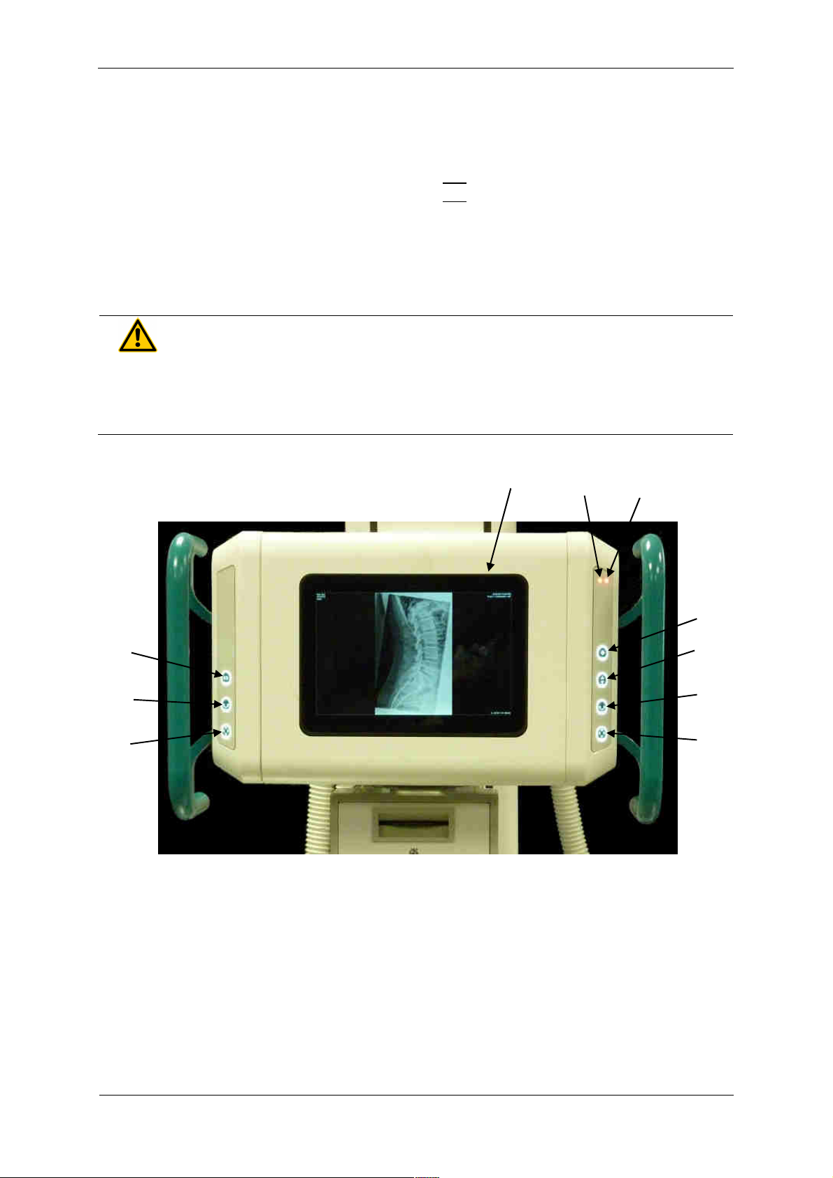
3.2.2 PROGNOST SH TOUCH
1 Touchdisplay of X-ray tube assembly
2 Brake release for horizontal movement of X-ray floor stand
3 Brake release for movement of X-ray tube assembly around the horizontal support arm axis
4 Brake release for vertical movement of X-ray tube arm and horizontal movement of X-ray floor stand
5 Brake release for vertical movement of X-ray tube arm and horizontal movement of X-ray floor stand
6 Brake release for movement of X-ray tube assembly around the horizontal support arm axis
7 Brake release for vertical movement of X-ray tube arm
8 Option: Brake release for transversal movement of X-ray tube arm (+230mm)
9 Option: Status-LED orange (if LED is on: X-ray tube arm is not engaged)
10 Option: Status-LED red (if LED on: X-ray flor stand is not engaged)
WARNING!
If the red LED on the right membrane ke pad lights up, the X-ra tube carrier
is not engaged! In this state no x-ra s ma be taken. The X-ra tube carrier
must first engage in one of the positions (0 / ± 90° / ± 180°)!
Operation is from the front (operating side) of the X-ray head.
If the operating unit is equipped with handles, the electromagnetic lock of one or more movements
can be released by thumb pressure on the keys of the operating unit and the tube head can be
brought into the desired position.
6
5
1
2
3
4
7
6
5
8
9
10

PRS 500 F
Instructions for use
5067
-
0
-
8
002
PROTEC GmbH & Co. KG, In den Dorfwiesen 14, 71720 Oberstenfeld, Germany
20
von
41
3.2.3 Foot pedal
To unlock the X-ray tube carrier, the foot lever (see Illustration Pos.1) must be operated downwards.
Hold the foot lever in this position and turn the X-ray tube carrier a little in the desired direction. For
further rotation, the foot lever does not have to be operated anymore. The detent in the new position
centers itself.
WARNING!
There is an increased risk of injur if the X-ra tube carrier is not engaged!
Detailed information please find in the accompanying User Manual PROGNOST SH.
1
Other manuals for PRS 500 F
2
This manual suits for next models
1
Table of contents
Other Pro-tec Diagnostic Equipment manuals

Pro-tec
Pro-tec PROGNOST XS User manual

Pro-tec
Pro-tec PRS 500 E Instruction sheet

Pro-tec
Pro-tec PRS 500 C User manual

Pro-tec
Pro-tec PROGNOST C User manual

Pro-tec
Pro-tec PRS 500 E User manual

Pro-tec
Pro-tec PRS 500 X User manual

Pro-tec
Pro-tec PRS 500 B User manual

Pro-tec
Pro-tec PRS 500 F User manual

Pro-tec
Pro-tec PRS 500 B User manual

Pro-tec
Pro-tec PRS 500 F User manual


