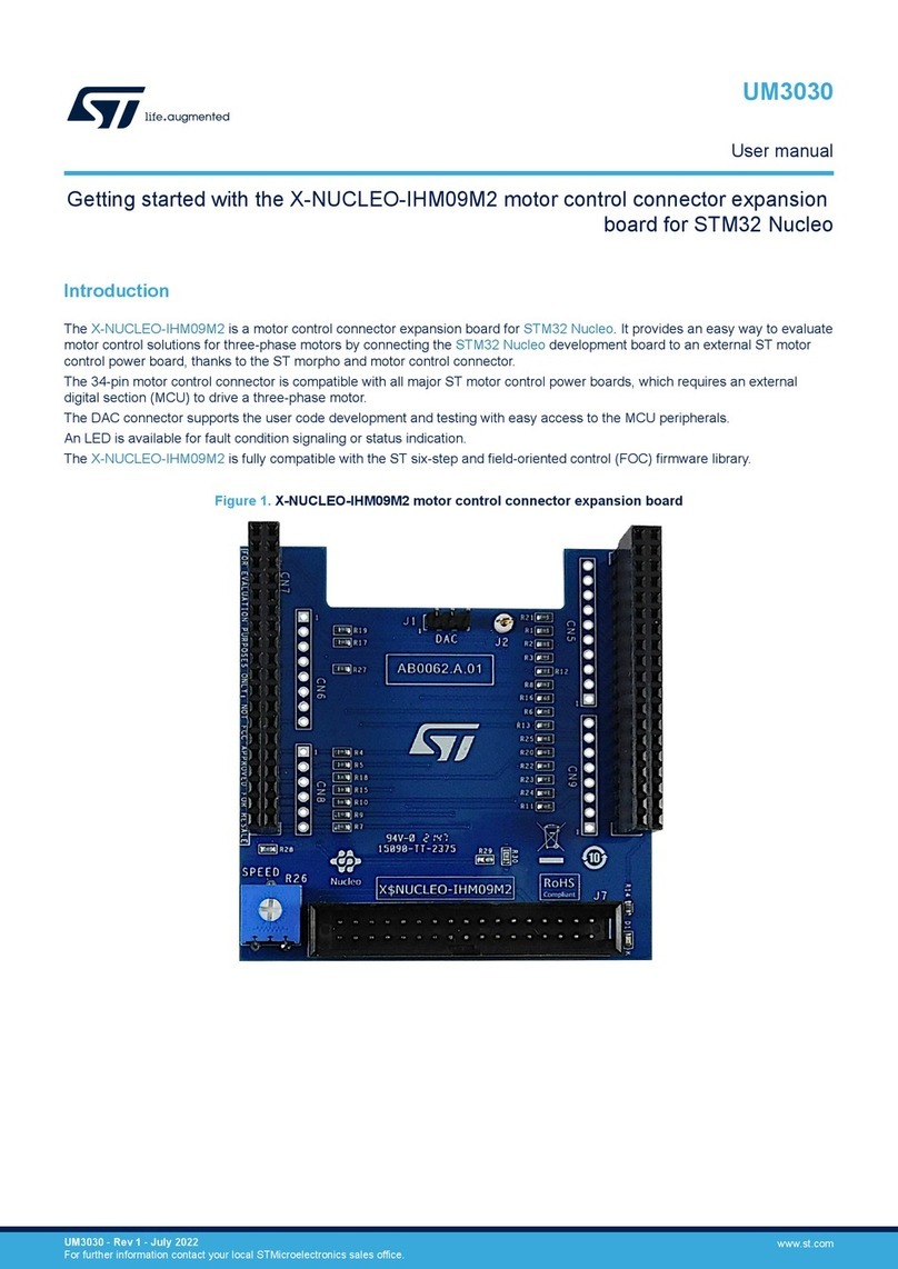
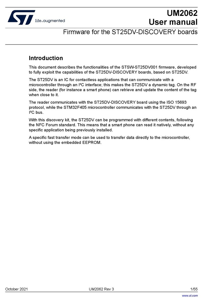
ST UM2033 User manual

April 2022 UM2033 Rev 4 1/44
1
UM2033
User manual
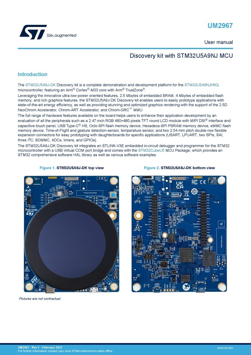
Discovery kit with STM32F769NI MCU
Introduction
The 32F769IDISCOVERY Discovery kit is a complete demonstration and development
platform for STMicroelectronics Arm®Cortex®-M7 core-based STM32F769NIH6
microcontroller. It features four I2Cs, six SPIs with three multiplexed simplex I2S,
2xSDMMC, four USARTs, four UARTs, three CAN buses, three 12-bit ADCs, two 12-bit
DACs, two SAIs, 8- to 14-bit digital camera module interface, internal 512+4-Kbyte SRAM
and 2-Mbyte flash memory, USB HS OTG and USB FS OTG, Ethernet MAC, FMC interface,
Quad-SPI interface and SWD debugging support.
The Discovery kit offers all required to get started quickly and develop applications easily.
The full range of hardware features available on the 32F769IDISCOVERY Discovery kit for
both STM32F769I-DISCO and STM32F769I-DISC1 variants (Refer to Figure 1:
STM32F769I-DISCO (Top view) and Figure 2: STM32F769I-DISC1 (Top view)), helps users
to evaluate the following peripherals: USB OTG HS, 10/100-Mbit Ethernet, microSD™,
USART, SAI Audio DAC
stereo with two audio jacks for input/output, ST MEMS digital
microphones, SDRAM, Quad-SPI flash memory, SPDIF input/output, and DSI interface LCD
with a capacitive multi-touch panel. The latter is only available on the STM32F769I-DISCO
(Refer to Figure 1).
ARDUINO®Uno V3 connectors allow easy connection of extension shields or daughterboards.
The integrated ST-LINK/V2-1 provides an embedded in-circuit debugger and programmer for
the STM32. The 32F769IDISCOVERY Discovery kit comes with the STM32 comprehensive
software HAL library together with various packaged software examples.
Figure 3. 32F769IDISCOVERY board (Bottom view)
Pictures are not contractual.
Figure 1. STM32F769I-DISCO (Top view) Figure 2. STM32F769I-DISC1 (Top view)
Bottom view of:
STM32F769I-DISCO and
STM32F769I-DISC1
www.st.com

Contents UM2033
2/44 UM2033 Rev 4
Contents
1 Features . . . . . . . . . . . . . . . . . . . . . . . . . . . . . . . . . . . . . . . . . . . . . . . . . . . 7
2 Ordering information . . . . . . . . . . . . . . . . . . . . . . . . . . . . . . . . . . . . . . . . 8
3 Development environment . . . . . . . . . . . . . . . . . . . . . . . . . . . . . . . . . . . . 9
3.1 System requirements . . . . . . . . . . . . . . . . . . . . . . . . . . . . . . . . . . . . . . . . . 9
3.2 Development toolchains . . . . . . . . . . . . . . . . . . . . . . . . . . . . . . . . . . . . . . . 9
4 Conventions . . . . . . . . . . . . . . . . . . . . . . . . . . . . . . . . . . . . . . . . . . . . . . . . 9
5 Hardware layout and configuration . . . . . . . . . . . . . . . . . . . . . . . . . . . . 10
5.1 The 32F769IDISCOVERY Discovery board layout . . . . . . . . . . . . . . . . . .11
5.2 The 32F769IDISCOVERY Discovery board mechanical drawing . . . . . . 13
5.3 Embedded ST-LINK/V2-1 . . . . . . . . . . . . . . . . . . . . . . . . . . . . . . . . . . . . . 14
5.3.1 Drivers . . . . . . . . . . . . . . . . . . . . . . . . . . . . . . . . . . . . . . . . . . . . . . . . . . 14
5.3.2 ST-LINK/V2-1 firmware upgrade . . . . . . . . . . . . . . . . . . . . . . . . . . . . . . 15
5.4 Power supply . . . . . . . . . . . . . . . . . . . . . . . . . . . . . . . . . . . . . . . . . . . . . . 16
5.5 Programming/debugging when the power supply is not from
ST-LINK (5 V link) . . . . . . . . . . . . . . . . . . . . . . . . . . . . . . . . . . . . . . . . . . . 19
5.6 Clock sources . . . . . . . . . . . . . . . . . . . . . . . . . . . . . . . . . . . . . . . . . . . . . . 19
5.7 Reset sources . . . . . . . . . . . . . . . . . . . . . . . . . . . . . . . . . . . . . . . . . . . . . 19
5.8 Audio . . . . . . . . . . . . . . . . . . . . . . . . . . . . . . . . . . . . . . . . . . . . . . . . . . . . 19
5.9 USB OTG HS . . . . . . . . . . . . . . . . . . . . . . . . . . . . . . . . . . . . . . . . . . . . . . 20
5.10 microSD™ card . . . . . . . . . . . . . . . . . . . . . . . . . . . . . . . . . . . . . . . . . . . . 20
5.11 Ethernet . . . . . . . . . . . . . . . . . . . . . . . . . . . . . . . . . . . . . . . . . . . . . . . . . . 20
5.12 Power over Ethernet . . . . . . . . . . . . . . . . . . . . . . . . . . . . . . . . . . . . . . . . . 20
5.13 SDRAM memory . . . . . . . . . . . . . . . . . . . . . . . . . . . . . . . . . . . . . . . . . . . 21
5.14 Quad-SPI NOR flash memory . . . . . . . . . . . . . . . . . . . . . . . . . . . . . . . . . 21
5.15 Virtual COM port . . . . . . . . . . . . . . . . . . . . . . . . . . . . . . . . . . . . . . . . . . . . 21
5.16 Buttons and LEDs . . . . . . . . . . . . . . . . . . . . . . . . . . . . . . . . . . . . . . . . . . 21
5.17 LCD MIPI DSI (with STM32F769I-DISCO only) . . . . . . . . . . . . . . . . . . . . 22
5.18 Adapter board from on-board DSI to HDMI
(optional accessory display) . . . . . . . . . . . . . . . . . . . . . . . . . . . . . . . . . . . 22

UM2033 Rev 4 3/44
UM2033 Contents
4
5.19 Adapter board from on-board DSI to external DSI
(optional accessory display) . . . . . . . . . . . . . . . . . . . . . . . . . . . . . . . . . . . 23
5.20 Wi-Fi®and extension I2C connector . . . . . . . . . . . . . . . . . . . . . . . . . . . . 24
5.20.1 Serial Wi-Fi®module . . . . . . . . . . . . . . . . . . . . . . . . . . . . . . . . . . . . . . . 24
5.20.2 Extension I2C board . . . . . . . . . . . . . . . . . . . . . . . . . . . . . . . . . . . . . . . . 24
6 Connectors . . . . . . . . . . . . . . . . . . . . . . . . . . . . . . . . . . . . . . . . . . . . . . . 25
6.1 Wi-Fi®and I2C extension connector (CN2) . . . . . . . . . . . . . . . . . . . . . . . 25
6.2 ARDUINO®Uno V3 connectors (CN11, CN14, CN13, and CN9) . . . . . . 26
6.3 USB OTG HS Micro-AB connector (CN15) . . . . . . . . . . . . . . . . . . . . . . . 27
6.4 Ethernet RJ45 connector (CN10) . . . . . . . . . . . . . . . . . . . . . . . . . . . . . . . 27
6.5 LCD MIPI DSI connector (CN1) . . . . . . . . . . . . . . . . . . . . . . . . . . . . . . . . 28
6.6 microSD™ connector (CN5) . . . . . . . . . . . . . . . . . . . . . . . . . . . . . . . . . . . 29
6.7 ST-LINK/V2-1 USB Micro-B connector (CN16) . . . . . . . . . . . . . . . . . . . . 29
6.8 Audio stereo speaker (JP2 and JP3) . . . . . . . . . . . . . . . . . . . . . . . . . . . . 30
6.9 Audio line output jack (CN7) . . . . . . . . . . . . . . . . . . . . . . . . . . . . . . . . . . . 30
6.10 Audio line input jack (CN6) . . . . . . . . . . . . . . . . . . . . . . . . . . . . . . . . . . . . 30
6.11 SPDIF input RCA connector (CN12) . . . . . . . . . . . . . . . . . . . . . . . . . . . . 30
6.12 SPDIF output RCA connector (CN8) . . . . . . . . . . . . . . . . . . . . . . . . . . . . 31
7 32F769IDISCOVERY I/O assignment . . . . . . . . . . . . . . . . . . . . . . . . . . . 32
8 32F769IDISCOVERY board information . . . . . . . . . . . . . . . . . . . . . . . . 39
8.1 Product marking . . . . . . . . . . . . . . . . . . . . . . . . . . . . . . . . . . . . . . . . . . . . 39
8.2 32F769IDISCOVERY product history . . . . . . . . . . . . . . . . . . . . . . . . . . . 39
8.2.1 Product identification 32F769I-DISCO/ . . . . . . . . . . . . . . . . . . . . . . . . . 39
8.2.2 Product identification DK32F769I$AU1 . . . . . . . . . . . . . . . . . . . . . . . . . 39
8.2.3 Product identification DK32F769I$AU2 . . . . . . . . . . . . . . . . . . . . . . . . . 40
8.3 Board revision history . . . . . . . . . . . . . . . . . . . . . . . . . . . . . . . . . . . . . . . . 40
8.3.1 Board MB1225 revision A-01 . . . . . . . . . . . . . . . . . . . . . . . . . . . . . . . . . 40
8.3.2 Board MB1225 revision B-01 . . . . . . . . . . . . . . . . . . . . . . . . . . . . . . . . . 40
8.3.3 Board MB1225 revision B-03 . . . . . . . . . . . . . . . . . . . . . . . . . . . . . . . . . 40
8.3.4 Board MB1225 revision C-01 . . . . . . . . . . . . . . . . . . . . . . . . . . . . . . . . . 40
8.3.5 Board MB1166 revision A-03 . . . . . . . . . . . . . . . . . . . . . . . . . . . . . . . . . 40
8.3.6 Board MB1166 revision A-09 . . . . . . . . . . . . . . . . . . . . . . . . . . . . . . . . . 41
8.4 Board known limitations . . . . . . . . . . . . . . . . . . . . . . . . . . . . . . . . . . . . . . 41
Contents UM2033
4/44 UM2033 Rev 4
8.4.1 Board MB1225 revision A-01 limitations . . . . . . . . . . . . . . . . . . . . . . . . 41
8.4.2 Board MB1225 revision B-01 limitations . . . . . . . . . . . . . . . . . . . . . . . . 41
8.4.3 Board MB1225 revision B-03 limitations . . . . . . . . . . . . . . . . . . . . . . . . 41
8.4.4 Board MB1225 revision C-01 limitations . . . . . . . . . . . . . . . . . . . . . . . . 41
8.4.5 Board MB1166 revision A-03 limitations . . . . . . . . . . . . . . . . . . . . . . . . 41
8.4.6 Board MB1166 revision A-09 limitations . . . . . . . . . . . . . . . . . . . . . . . . 41
9 Federal Communications Commission (FCC) and
Innovation, Science and Economic Development
Canada (ISED) Compliance Statements . . . . . . . . . . . . . . . . . . . . . . . . 42
9.1 FCC Compliance Statement . . . . . . . . . . . . . . . . . . . . . . . . . . . . . . . . . . . 42
9.1.1 Part 15.19 . . . . . . . . . . . . . . . . . . . . . . . . . . . . . . . . . . . . . . . . . . . . . . . 42
9.1.2 Part 15.21 . . . . . . . . . . . . . . . . . . . . . . . . . . . . . . . . . . . . . . . . . . . . . . . 42
9.1.3 Part 15.105 . . . . . . . . . . . . . . . . . . . . . . . . . . . . . . . . . . . . . . . . . . . . . . 42
9.2 ISED Compliance Statement . . . . . . . . . . . . . . . . . . . . . . . . . . . . . . . . . . 42
9.2.1 Compliance Statement . . . . . . . . . . . . . . . . . . . . . . . . . . . . . . . . . . . . . 42
9.2.2 Déclaration de conformité . . . . . . . . . . . . . . . . . . . . . . . . . . . . . . . . . . . 42
Revision history . . . . . . . . . . . . . . . . . . . . . . . . . . . . . . . . . . . . . . . . . . . . . . . . . . . . 43

UM2033 Rev 4 5/44
UM2033 List of tables
5
List of tables
Table 1. List of the order codes . . . . . . . . . . . . . . . . . . . . . . . . . . . . . . . . . . . . . . . . . . . . . . . . . . . . . 8
Table 2. List of the order codes for the display accessories. . . . . . . . . . . . . . . . . . . . . . . . . . . . . . . . 8
Table 3. ON/OFF conventions . . . . . . . . . . . . . . . . . . . . . . . . . . . . . . . . . . . . . . . . . . . . . . . . . . . . . . 9
Table 4. Control port assignment . . . . . . . . . . . . . . . . . . . . . . . . . . . . . . . . . . . . . . . . . . . . . . . . . . . 21
Table 5. Wi-Fi®and I2C extension connector (CN2) . . . . . . . . . . . . . . . . . . . . . . . . . . . . . . . . . . . . 25
Table 6. ARDUINO®connectors (CN11, CN14, CN13, and CN9) . . . . . . . . . . . . . . . . . . . . . . . . . . 26
Table 7. USB OTG HS Micro-AB (CN15) . . . . . . . . . . . . . . . . . . . . . . . . . . . . . . . . . . . . . . . . . . . . . 27
Table 8. Ethernet RJ45 connector (CN10) . . . . . . . . . . . . . . . . . . . . . . . . . . . . . . . . . . . . . . . . . . . . 27
Table 9. LCD MIPI DSI connector (CN1) . . . . . . . . . . . . . . . . . . . . . . . . . . . . . . . . . . . . . . . . . . . . . 28
Table 10. microSD™ connector (CN5) . . . . . . . . . . . . . . . . . . . . . . . . . . . . . . . . . . . . . . . . . . . . . . . . 29
Table 11. USB Micro-B connector (CN16) . . . . . . . . . . . . . . . . . . . . . . . . . . . . . . . . . . . . . . . . . . . . . 30
Table 12. SPDIF input RCA connector (CN12) . . . . . . . . . . . . . . . . . . . . . . . . . . . . . . . . . . . . . . . . . 30
Table 13. SPDIF output RCA connector (CN8) . . . . . . . . . . . . . . . . . . . . . . . . . . . . . . . . . . . . . . . . . 31
Table 14. 32F769IDISCOVERY I/O assignment . . . . . . . . . . . . . . . . . . . . . . . . . . . . . . . . . . . . . . . . 32
Table 15. Document revision history . . . . . . . . . . . . . . . . . . . . . . . . . . . . . . . . . . . . . . . . . . . . . . . . . 43

List of figures UM2033
6/44 UM2033 Rev 4
List of figures
Figure 1. STM32F769I-DISCO (Top view). . . . . . . . . . . . . . . . . . . . . . . . . . . . . . . . . . . . . . . . . . . . . . 1
Figure 2. STM32F769I-DISC1 (Top view) . . . . . . . . . . . . . . . . . . . . . . . . . . . . . . . . . . . . . . . . . . . . . . 1
Figure 3. 32F769IDISCOVERY board (Bottom view) . . . . . . . . . . . . . . . . . . . . . . . . . . . . . . . . . . . . . 1
Figure 4. Hardware block diagram. . . . . . . . . . . . . . . . . . . . . . . . . . . . . . . . . . . . . . . . . . . . . . . . . . . 10
Figure 5. 32F769IDISCOVERY top layout. . . . . . . . . . . . . . . . . . . . . . . . . . . . . . . . . . . . . . . . . . . . . 11
Figure 6. 32F769IDISCOVERY bottom layout. . . . . . . . . . . . . . . . . . . . . . . . . . . . . . . . . . . . . . . . . . 12
Figure 7. 32F769IDISCOVERY mechanical drawing. . . . . . . . . . . . . . . . . . . . . . . . . . . . . . . . . . . . . 13
Figure 8. USB composite device . . . . . . . . . . . . . . . . . . . . . . . . . . . . . . . . . . . . . . . . . . . . . . . . . . . . 14
Figure 9. ext5V (CN3) from Ext 5 V (JP1) . . . . . . . . . . . . . . . . . . . . . . . . . . . . . . . . . . . . . . . . . . . . . 16
Figure 10. ext5V (CN3) from VIN (CN11) . . . . . . . . . . . . . . . . . . . . . . . . . . . . . . . . . . . . . . . . . . . . . . 16
Figure 11. chgr (CN3) . . . . . . . . . . . . . . . . . . . . . . . . . . . . . . . . . . . . . . . . . . . . . . . . . . . . . . . . . . . . . 17
Figure 12. poe5V (CN3). . . . . . . . . . . . . . . . . . . . . . . . . . . . . . . . . . . . . . . . . . . . . . . . . . . . . . . . . . . . 17
Figure 13. stlk (CN3) . . . . . . . . . . . . . . . . . . . . . . . . . . . . . . . . . . . . . . . . . . . . . . . . . . . . . . . . . . . . . . 18
Figure 14. usbhs (CN3) . . . . . . . . . . . . . . . . . . . . . . . . . . . . . . . . . . . . . . . . . . . . . . . . . . . . . . . . . . . . 18
Figure 15. 4-inch WVGA TFT DSI LCD daughterboard. . . . . . . . . . . . . . . . . . . . . . . . . . . . . . . . . . . . 22
Figure 16. DSI to HDMI adapter board . . . . . . . . . . . . . . . . . . . . . . . . . . . . . . . . . . . . . . . . . . . . . . . . 23
Figure 17. DSI to HDMI adapter board . . . . . . . . . . . . . . . . . . . . . . . . . . . . . . . . . . . . . . . . . . . . . . . . 23
Figure 18. On-board DSI to external DSI. . . . . . . . . . . . . . . . . . . . . . . . . . . . . . . . . . . . . . . . . . . . . . . 23
Figure 19. On-board DSI to external DSI. . . . . . . . . . . . . . . . . . . . . . . . . . . . . . . . . . . . . . . . . . . . . . . 23
Figure 20. Wi-Fi®module (ESP8266-01). . . . . . . . . . . . . . . . . . . . . . . . . . . . . . . . . . . . . . . . . . . . . . . 24
Figure 21. Wi-Fi®and I2C extension connector (CN2) front view . . . . . . . . . . . . . . . . . . . . . . . . . . . . 25
Figure 22. Wi-Fi®and I2C extension connector (CN2) front view . . . . . . . . . . . . . . . . . . . . . . . . . . . . 25
Figure 23. USB OTG Micro-AB connector (CN15) front view . . . . . . . . . . . . . . . . . . . . . . . . . . . . . . . 27
Figure 24. Ethernet RJ45 connector (CN10) front view . . . . . . . . . . . . . . . . . . . . . . . . . . . . . . . . . . . . 27
Figure 25. LCD MIPI DSI connector (CN1) front view . . . . . . . . . . . . . . . . . . . . . . . . . . . . . . . . . . . . . 28
Figure 26. microSD™ connector (CN5) front view. . . . . . . . . . . . . . . . . . . . . . . . . . . . . . . . . . . . . . . . 29
Figure 27. USB Micro-B connector (CN16) front view . . . . . . . . . . . . . . . . . . . . . . . . . . . . . . . . . . . . . 30

UM2033 Rev 4 7/44
UM2033 Features
43
1 Features
•STM32F769NIH6 Arm®(a)-based microcontroller with 2 Mbytes of flash memory and
532 Kbytes of RAM, in a TFBGA216 package
•4-inch 800 x 472-pixel capacitive touch TFT color LCD with serial interface (On
STM32F769I-DISCO only)
•Optional display accessories: HDMI and DSI adapters
•SAI audio codec
•Four digital ST MEMS microphones on DFSDM inputs
•128-Mbit SDRAM
•512-Mbit Quad-SPI flash memory
•Reset and user push-buttons
•Board connectors:
–MIPIDSI
®
– 8- to 14-bit digital camera
– SPDIF RCA input and output
– Audio line input and output jacks
– Stereo speaker output
– microSD™. card holder with included card
–Wi.Fi
®or Ext-EEP daughterboard
– USB Micro-B
– USB Micro-AB
– IEEE-802.3-2002 compliant Ethernet
– ARDUINO®Uno V3
•On-board ST-LINK/V2-1 debugger/programmer with USB re-enumeration capability:
mass storage, Virtual COM port, and debug port
•Flexible power-supply options:
– ST-LINK/V2-1 USB connector
– USB OTG HS connector
– 5 V delivered by RJ45 (Power over Ethernet)
– 5 V delivered by ARDUINO®or external connector
– USB charger
•Power Over Ethernet based on IEEE 802.3af (Powered device from 48 to 5 V, 3 W)
•External application power supply: 3.3 V and 5 V
•Comprehensive free software libraries and examples available with the STM32Cube
MCU Package
•Support of a wide choice of Integrated Development Environments (IDEs) including
IAR Embedded Workbench®, MDK-ARM, and STM32CubeIDE
a. Arm is a registered trademark of Arm Limited (or its subsidiaries) in the US and/or elsewhere.

Ordering information UM2033
8/44 UM2033 Rev 4
2 Ordering information
To order the 32F769IDISCOVERY Discovery kit, refer to Table 1. Additional information is
available from the datasheet and reference manual of the target microcontroller.
To order the optional display accessories for the 32F769IDISCOVERY Discovery kit, refer to
Table 2.
Table 1. List of the order codes
Order code Board reference Target STM32
STM32F769I-DISCO – MB1225(1)
–MB1166
(2)
1. Mother board
2. 4-inch WVGA TFT LCD daughterboard
STM32F769NIH6
Table 2. List of the order codes for the display accessories
Order code Product description
B-LCDAD-RPI1 15-pin single row Flexible Printed Circuit DSI adapter board
B-LCDAD-HDMI1 DSI to HDMI adapter

UM2033 Rev 4 9/44
UM2033 Development environment
43
3 Development environment
3.1 System requirements
•Multi.OS support: Windows®10, Linux® (a) 64-bit, or macOS® (b)
•USB Type-A or USB Type-C®to Micro-B cable
3.2 Development toolchains
•IAR Systems - IAR Embedded Workbench® (c)
•Keil®- MDK-ARM(c)
•STMicroelectronics - STM32CubeIDE
4 Conventions
Table 3 defines some conventions used in the present document.
a. Linux®is a registered trademark of Linus Torvalds.
b. macOS®is a trademark of Apple Inc., registered in the U.S. and other countries and regions.
All other trademarks are the property of their respective owners.
c. On Windows®only.
Table 3. ON/OFF conventions
Convention Definition
Jumper JPx ON Jumper fitted
Jumper JPx OFF Jumper not fitted
Jumper JPx [1-2] Jumper fitted between pin 1 and pin 2
Solder bridge SBx ON SBx connections closed by 0 Ωresistor
Solder bridge SBx OFF SBx connections left open
Resistor Rx ON Resistor soldered
Resistor Rx OFF Resistor not soldered
Capacitor Cx ON Capacitor soldered
Capacitor Cx OFF Capacitor not soldered

Hardware layout and configuration UM2033
10/44 UM2033 Rev 4
5 Hardware layout and configuration
The 32F769IDISCOVERY Discovery board is designed around the STM32F769NIH6
(TFBGA216 package). The hardware block diagram (Refer to Figure 4) illustrates the
connections between the STM32F769NIH6 and the peripherals (SDRAM, Quad-SPI flash
memory, LCD DSI connector, USB OTG connectors, USART, Ethernet, Audio, SPDIF RCA
in, SPDIF RCA out, microSD™ card, ARDUINO®Uno shields, and embedded ST-LINK).
Figure 5 and Figure 6 help users locate these features on the Discovery board. The
mechanical dimensions of the Discovery board are shown in Figure 7.
Figure 4. Hardware block diagram
MSv40775V1
STM32F769NIH6
Audio DAC and
Amplifier
RTC
Ethernet PHY and
RJ45 connector
SWD
3.3V Power
Supply
32KHz crystal
ST-LINK/V2-1
I2C
RMII
SAI
Wi-Fi or EXT I2C
Boards connector
Capacitive
multi-point
touchscreen
25MHz Oscillator
LEDs, push-button
and wakeup
GPIO
HSI
HS PHY and
Micro USB connector
OTG
HS
SDRAM FMC
LCD DSI
connector
DSI
QSPI QSPI Flash
SPDIF_TX SPDIF Output
and RCA connector
VCP
UART
ARDUINO UNO
shield connectors GPIOs
SPDIF_RX SPDIF Decoder Input
and RCA connector
ESP8266 Wi-Fi RX/TX
Power Over
Ethernet 48V
(5V, 3W)
microSD card
connector SDMMC
UART
Stereo jack
Line input
Stereo jack
Line input

UM2033 Rev 4 11/44
UM2033 Hardware layout and configuration
43
5.1 The 32F769IDISCOVERY Discovery board layout
Figure 5. 32F769IDISCOVERY top layout
512-Mbit Quad-SPI
flash memory
LCD with
MIPI DSI connector
PoE converter
around PM8800A
5 V external
connector
User
push-button
ST-LINK COM
LED
Four ST-MEMS
microphones on
DFSDM inputs
Fault power
LED
Power
LED
USB HS
LED
Overcurrent
LED
User
LEDs
ARDUINO
®
LED
User
push-button
Wi-Fi
®
or Ext-EEP
daughterboard
connector

Hardware layout and configuration UM2033
12/44 UM2033 Rev 4
Figure 6. 32F769IDISCOVERY bottom layout
microSD™
card holder
Audio line
output jack
Stereo speaker
outputs
SPDIF RCA
output
connector
128-Mbit
SDRAM
Power
supply
selector
SPDIF RCA
input
connector
Audio codec
Audio line
input jack
STM32F769NIH6
microcontroller
ARDUINO®
connectors
RJ45
Ethernet
connector
STM32F103CBT6
for ST-LINK
ST-LINK/V2-1 with
Micro-B connector
USB OTG HS with
Micro-AB connector

UM2033 Rev 4 13/44
UM2033 Hardware layout and configuration
43
5.2 The 32F769IDISCOVERY Discovery board mechanical
drawing
Figure 7. 32F769IDISCOVERY mechanical drawing
CN12
CN8
R102
C87
JP3
R115
R116 C94
C95
R111
C120
TP20
TP106
TP108
C79
C73
C71
TP105
TP109
R100
R101
TP107
R78 C57
JP2
R114
U16
C91
C90
C92
C93
C119
C118
U11
C67
R117
C117
U15
R112
U14
C100
R87
C64
C65
C59
C82
R95
R94
C78
C74
R88
C63
TP8
TP7
TP6
R77
CN7
CN13 CN9
C58
SB15
JP4
SB13
SB14
R109
C96
SB12
SB11
U12
R86
C62
T5
C130
C127
R98
C85
R92
R93
TP18 CN6
R130
R132
R131 C125
U17
C114
C115
TP26
TP22 C72
U13
TP100
TP17
TP16 R90
R91
R89
TP13
R129
C136
C137
C138 C112
C113
C111
TP14
TP15
R83
TP12
CN5
C148
U21
TP28
C135
C124 C109
C108
C110 R82
TP9
C156
C153
R134
C147
C134
C133
C144
C123
C105
C106
C104
C107
R80
R81
TP11
CN15
C150
C149
L8
R142
R139
R136
R126
C145 X4
C131
TP27
C126
C128
C116
C101
C103
C102
R79
C68
C69
L7
D13
U20
L6 R110
TP101
R107
X2
C99
R108
R106
C97
C86
C83
C88
C80
C76
R76 R73
C154
R137
D12
R125
R133
R128
R123
R124 CN14 CN11 C98 C77C84
X1
TP21
TP102
R104
R99
R97
TP2
R8
C157
R147
R148
R149
R146
R143
C151
SB22
SB21
D11
R141
R138
R135
R127
C143
R122
R23
R103
C22
D3
R24
C24
R25
TP3
R7
L3
TP1
R145
U19
R121
C142
X3
C140
R118
C132
C20
C61
C60
C141
R119
R120
SB16
T4
T100
R85
C200
L4
C155
CN16
R144
JP5
D9
R74
R150
U22
C146
SB19
SB18
SB20
SB17
U10
SB23
R140
C152
C129
C139
U18
C122 R105
T2
C66
R84
D10
D2
R75
CN3
R113
C121
R22
C21
CN10
R96
4
8
8 5
2
16 9
58
2
1
8
10
9
5
1
A
16
17
8
9
6
1
8
1
36
37
48
4
4
24
25
12
13
3
A
15
R
R
A
1
9
1
A
2425
32
9
A1
H
118
10
8
5
4
91
SPDIF RX
SPDIF TX
Wifi or I2C ext
spk R
CN2
spk L
B
B
Line Out
AVDD
D0
D2
D1
D4
D3
D6
D5
D7
D9
D8
D11
D10
D13
D12
GND
D14
D15
Idd
Line In
uSD
USB HS
A5
A3
A4
A1
A2
A0
GND
VIN
5V
GND
NRST
3V3
IOREF5
nc
VCP_TX
USB ST_LINK
VCP_RX
usbhs
stlk
Ethernet
poe5V
ext5V
Ext 5V
5V
chgr
JP1
88mm
28.49mm
77.8mm
5.2mm
5mm
37.7mm
11.61mm
23.24mm
5mm
30.71mm
5mm
16.76mm 22.04mm
4.06mm
116.74mm
127mm
48.26mm
116.74mm
22.86mm
30.4mm
37.77mm
5.26mm
5mm
11.61mm
5.2mm
5.26mm
43.31mm
30.72mm

Hardware layout and configuration UM2033
14/44 UM2033 Rev 4
5.3 Embedded ST-LINK/V2-1
The ST-LINK/V2-1 programming and debugging tool is integrated on the
32F769IDISCOVERY Discovery board. Compared to ST-LINK/V2 the changes are listed
below.
The new features supported on ST-LINK/V2-1 are:
•USB software re-enumeration
•Virtual COM port interface on USB
•Mass storage interface on USB
•USB power management request for more than 100mA power on USB
These features are no more supported on ST-LINK/V2-1:
•SWIM interface
•Application voltage lower than 3 V
For general information concerning the debugging and programming features that are
common to both versions V2 and V2-1, refer to the user manual ST-LINK/V2 in-circuit
debugger/programmer for STM8 and STM32 (UM1075).
5.3.1 Drivers
The ST-LINK/V2-1 requires a dedicated USB driver for Windows®available at the
www.st.com website.
In case the 32F769IDISCOVERY Discovery board is connected to the PC before the driver
is installed, some 32F769IDISCOVERY interfaces may be declared as unknown in the PC
device manager. In this case, the user must install the driver files and update the driver of
the connected device from the device manager.
Note: Prefer using the ‘USB Composite Device’ handle for a full recovery.
Figure 8. USB composite device

UM2033 Rev 4 15/44
UM2033 Hardware layout and configuration
43
5.3.2 ST-LINK/V2-1 firmware upgrade
The ST-LINK/V2-1 embeds a firmware upgrade mechanism for the in-situ upgrade through
the USB port. As the firmware may evolve during the lifetime of the ST-LINK/V2-1 product
(for example new functionalities, bug fixes, support for new microcontroller families), it is
recommended to visit the www.st.com website before starting to use the
32F769IDISCOVERY Discovery board and periodically, to stay up-to-date with the latest
firmware version.

Hardware layout and configuration UM2033
16/44 UM2033 Rev 4
5.4 Power supply
The 32F769IDISCOVERY Discovery board is designed to be powered by the 5 V DC power
supply. It is possible to configure the Discovery board to use any of the following five
sources for the power supply:
•5 V DC power adapter connected to JP1 (Ext 5 V). In this case, the
32F769IDISCOVERY Discovery board must be powered by a power supply unit or by
auxiliary equipment complying with the standard EN-60950-1: 2006+A11/2009, and
must be Safety Extra Low Voltage (SELV) with limited power capability (5 V power
source on the Ext 5 V silkscreen of JP1). Refer to Figure 9:
Figure 9. ext5V (CN3) from Ext 5 V (JP1)
•7-12 V DC power from CN11 pin named VIN on silkscreen, the extension connectors
for ARDUINO®UNO shields or daughterboards (5 V power source on the Ext 5 V
silkscreen of JP1). The input current capability is linked to the input voltage (Refer to
Figure 10):
– 800 mA input current when Vin = 7 V
– 450 mA input current when 7 V < Vin (< or =) 9 V
– 250 mA input current when 9 V < Vin (< or =) 12 V
Figure 10. ext5V (CN3) from VIN (CN11)

UM2033 Rev 4 17/44
UM2033 Hardware layout and configuration
43
•5 V DC power charger connected to USB ST-LINK (CN16). In this case, if the
32F769IDISCOVERY Discovery board is powered by an external USB charger then
the debug features are not available. If the board is connected to the PC instead, the
limitation is no more effective with a high risk to damage the PC (5 V power source on
the chgr silkscreen of CN3). Refer to Figure 11:
Figure 11. chgr (CN3)
•48 V DC power from RJ45 Ethernet connector (CN10). In this case, the on-board
module PoE (Power over Ethernet) generates the 5 V and it can provide up to 600 mA.
This module is a Powered Device complying with the standard IEEE802.3af, class 1 /
2. The external power supply must be fully IEEE 802.3af compliant (5 V power source
on the poe5V silkscreen of CN3). Refer to Figure 12:
Figure 12. poe5V (CN3)
•5 V DC power with limitation from CN16, the USB type Micro-B connector of
ST-LINK/V2-1 (USB 5 V power source on the stlk silkscreen of CN3). It is the default
setting. If the USB enumeration succeeds (as explained below), the ST-LINK 5 V link
power is enabled, by asserting the PWR_ENn signal. This pin is connected to a power
switch ST890, which powers the board. This power switch also features a current
limitation to protect the PC in case of a short-circuit on the board (more than 700 mA).
Refer to Figure 13.
The 32F769IDISCOVERY Discovery board can be powered from the stlk ST-LINK USB
connector (CN16), but only the ST-LINK circuit has the power before the USB enumeration
because the host PC only provides 100 mA to the board at that time. During the USB
enumeration, the 32F769IDISCOVERY Discovery board asks for 500 mA of current to the
host PC. If the host can provide the required power, the enumeration finishes by a
SetConfiguration command, and then, the power transistor ST890 is switched ON, the red

Hardware layout and configuration UM2033
18/44 UM2033 Rev 4
LED LD6 is turned ON, thus the 32F769IDISCOVERY Discovery board can consume a
maximum of 500 mA of current, but no more. If the host is not able to provide the requested
current, the enumeration fails. Therefore the ST890 remains OFF and the STM32 part
including the extension board is not powered. As a consequence, the red LED LD6 remains
turned OFF. In this case, it is mandatory to use an external power supply.
Figure 13. stlk (CN3)
Note: In case the board is powered by a USB charger, there is no USB enumeration, so the led
LD2 remains set to OFF permanently and the board is not powered. Only in this specific
case, the resistor (R138) needs to be soldered, to allow the board to be powered anyway.
The LED LD6 is lit when the 32F769IDISCOVERY Discovery board is powered by the 5 V
correctly.
Caution: Do not connect the PC to the ST-LINK (CN16) when R138 is soldered. The PC may be
damaged or the board not powered correctly.
•5 V DC power with 500 mA limitation (CN15), the USB OTG HS Micro-AB connector
(5 V power source on the usbhs silkscreen of CN3). Refer to Figure 14:
Figure 14. usbhs (CN3)

UM2033 Rev 4 19/44
UM2033 Hardware layout and configuration
43
5.5 Programming/debugging when the power supply is not from
ST-LINK (5 V link)
It is mandatory to power the board first using Ext 5 V on JP1, Vin on CN11, Ethernet (CN10),
or usbhs (CN15), then connecting the USB cable to the PC. Proceeding this way ensures
that the enumeration succeeds thanks to the external power source.
The following power sequence procedure must be respected:
1. Connect the jumper CN3 on (ext5V) or (usbhs) or (poe5V)
2. Connect the external power source to JP1, CN11, CN10, or CN15
3. Check the red LED LD2 is turned ON
4. Connect the PC to the USB connector (CN16)
If this order is not respected, the board may be powered first by VBUS from the ST-LINK,
and the following risks may be encountered:
1. If more than 500 mA current is needed by the board, the PC may be damaged or the
current can be limited by the PC. As a consequence, the board is not powered
correctly.
2. 500 mA is requested at the enumeration: in this case, there is a risk that the request is
rejected and the enumeration does not succeed if the PC cannot provide such current.
5.6 Clock sources
Up to three clock sources are available, as described below:
•X1, 24MHz oscillator for USB OTG HS PHY
•X2, 25MHz oscillator for the STM32F769NIH6 microcontroller and Ethernet PHY
•X3, 32KHz crystal for the STM32F769NIH6 embedded RTC
5.7 Reset sources
The reset signal of the 32F769IDISCOVERY Discovery board is active low and the reset
sources are:
•Reset button (B2)
•ARDUINO®Uno shield board (CN11)
•Embedded ST-LINK/V2-1
5.8 Audio
An audio codec with 4 DACs and 2 ADCs is connected to the SAI interface of the
STM32F769NIH6. It communicates with the STM32F769NIH6 via an I2C bus shared with
the touch panel of the LCD DSI:
•The analog line input is connected to the ADC of the codec device via an audio jack
(CN6).
•The analog line output is connected to the DAC of the codec device via an audio jack
(CN7).

Hardware layout and configuration UM2033
20/44 UM2033 Rev 4
•Two external speakers can be connected to the codec device via the JP2 for the left
speaker and JP3 for the right speaker.
•Four digital microphones (ST MEMS microphone) are available on the
32F769IDISCOVERY Discovery board. They are connected to the input digital
microphones of the STM32F769NIH6 and are managed by the DFSDM functionality.
•One coaxial connector (CN12) is implemented on the 32F769IDISCOVERY to receive
external audio data compatible with SPDIF specifications.
•One coaxial connector (CN8) is implemented on the 32F769IDISCOVERY to output
external audio data compatible with SPDIF specifications.
5.9 USB OTG HS
32F769IDISCOVERY Discovery board supports USB OTG high-speed communication via a
USB Micro-AB connector and a USB high-speed PHY for high-speed function.
The Discovery board can be powered by USB connectors at 5 V DC with a 500 mA current
limitation.
A USB power switch is also connected to VBUS and provides power to CN15. The green
LED LD5 is lit in one of these cases:
•Power switch is ON and 32F769IDISCOVERY works as a USB host
•VBUS is powered by another USB host when 32F769IDISCOVERY works as a USB
device
The red LED LD4 is lit when an overcurrent occurs.
Note: 32F769IDISCOVERY Discovery board should be powered by an external power supply
when using the OTG function.
5.10 microSD™ card
The 2-Gbyte (or more) microSD™ card connected to the SDMMC2 port of STM32F769NIH6
is supported by the board.
5.11 Ethernet
The 32F769IDISCOVERY Discovery board supports 10/100-Mbit Ethernet communication
by a PHY and integrates an RJ45 connector. Ethernet PHY is connected to the
STM32F769NIH6 via an RMII interface.
The oscillator X2 generates a 25 MHz clock for the PHY, the PHY RMII_REF_CLK
generates the 50 MHz clock for the STM32F769NIH6.
5.12 Power over Ethernet
The 32F769IDISCOVERY Discovery board integrates a power module that uses Ethernet.
This module is an IEEE802.3af compliant, class 1 / 2 PoE converter based on the simple
diode rectified Flyback topology around the PM8800A component from ST. This module
''Powered Device'' accepts an input voltage of 48 V and can provide 5 V with 600 mA.
Table of contents
Other ST Computer Hardware manuals

ST
ST X-NUCLEO-IHM09M1 User manual

ST
ST STEVAL-BCN002V1B User manual

ST
ST STEVAL-ST25R3916B User manual

ST
ST STM32G071B-DISCO User manual

ST
ST X-NUCLEO-IDW01M1 User manual

ST
ST STEVAL-IFP041V1 User manual

ST
ST M41ST85W User manual

ST
ST I-CUBE-LRWAN User manual

ST
ST EVSPIN958 User manual

ST
ST X-NUCLEO-SNK1M1 User manual

ST
ST X-NUCLEO-OUT16A1 User manual

ST
ST METERS AND MORE UM2241 User manual

ST
ST STM32F038 6 Series User manual

ST
ST STM32Cube User manual

ST
ST STM32 Nucleo User manual

ST
ST TIP120 User manual

ST
ST STM32F3DISCOVERY User manual

ST
ST STM32F10 Series Installation and operating instructions

ST
ST AN5717 Installation and operating instructions

ST
ST STM32Cube User manual