ST X-NUCLEO-GFX01M Series User manual

Introduction
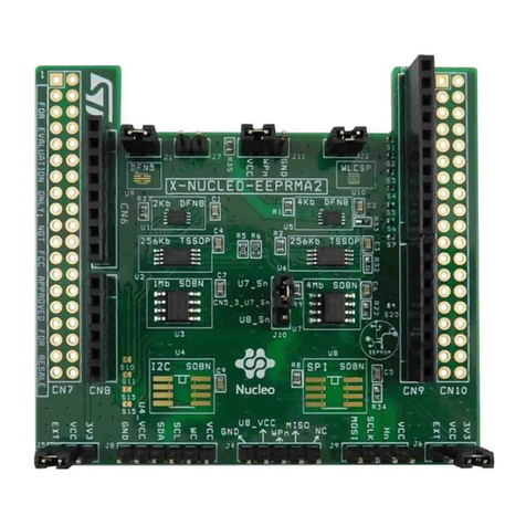
The X-NUCLEO-GFX01M1 and X-NUCLEO-GFX01M2 expansion boards (X-NUCLEO-GFX01Mx) add graphic user interface
(GUI) capability to STM32 Nucleo-64 boards.
They feature a 2.2" SPI QVGA TFT display as well as a 64-Mbit SPI NOR Flash memory for storing graphic images, texts and
texture. The expansion boards also offer a joystick for GUI navigation.
X-NUCLEO-GFX01M1 uses the ST morpho connector and supports only one SPI. It is compatible with the following
Nucleo-64 boards: NUCLEO-F030R8, NUCLEO-F070RB, NUCLEO-F072RB, NUCLEO-F091RC, NUCLEO-F401RE, NUCLEO-
F410RB, NUCLEO-F411RE, NUCLEO-F446RE, NUCLEO-G071RB, NUCLEO-L053R8, NUCLEO-L073RZ, NUCLEO-L412RB-
P, NUCLEO-L433RC-P, NUCLEO-L452RE, NUCLEO-L452RE-P, and NUCLEO-L476RG.
X-NUCLEO-GFX01M2 uses the ST morpho connector and suppports up to two SPIs. It is compatible with the following
Nucleo-64 boards, which include the X-NUCLEO-GFX01M1-compatible boards: NUCLEO-F030R8, NUCLEO-F070RB,
NUCLEO-F072RB, NUCLEO-F091RC, NUCLEO-F103RB, NUCLEO-F302R8, NUCLEO-F303RE, NUCLEO-F334R8, NUCLEO-
F401RE, NUCLEO-F410RB, NUCLEO-F411RE, NUCLEO-F446RE, NUCLEO-G070RB, NUCLEO-G071RB, NUCLEO-
G0B1RE, NUCLEO-G431RB, NUCLEO-G474RE, NUCLEO-G491RE, NUCLEO-L010RB, NUCLEO-L053R8, NUCLEO-
L073RZ, NUCLEO-L152RE, NUCLEO-L412RB-P, NUCLEO-L433RC-P, NUCLEO-L452RE, NUCLEO-L452RE-P, NUCLEO-
L476RG, NUCLEO-WB15CC, NUCLEO-WB55RG, and NUCLEO-WL55JC.
Figure 1. X-NUCLEO-GFX01Mx top view Figure 2. X-NUCLEO-GFX01Mx bottom view
Pictures are not contractual.
SPI display expansion boards for STM32 Nucleo-64
UM2750
User manual
UM2750 - Rev 2 - October 2021
For further information contact your local STMicroelectronics sales office. www.st.com

1Features
• 2.2" SPI QVGA TFT LCD
• 64-Mbit SPI NOR Flash memory
• Joystick for easy menu navigation
• Compatible with selected STM32 Nucleo-64 boards using the ST morpho interface
UM2750
Features
UM2750 - Rev 2 page 2/31

2Ordering information
To order the X-NUCLEO-GFX01Mx SPI display expansion boards for STM32 Nucleo-64, refer to Table 1.
Table 1. Ordering information
Order code Board reference Differentiating features
X-NUCLEO-GFX01M1
MB1642(1)
First-generation product compatible with a limited set of STM32 Nucleo-64 boards.
X-NUCLEO-GFX01M2 Second-generation product compatible with a broader set of STM32 Nucleo-64
boards.
1. MB1642B for X-NUCLEO-GFX01M1, MB1642D for X-NUCLEO-GFX01M2.
The STM32 Nucleo-64 boards feature STM32 32-bit microcontrollers based on the Arm® Cortex®‑M processor.
Note: Arm is a registered trademark of Arm Limited (or its subsidiaries) in the US and/or elsewhere.
UM2750
Ordering information
UM2750 - Rev 2 page 3/31

3Development environment
3.1 Demonstration software
The demonstration software supporting the X-NUCLEO-GFX01M1 and X-NUCLEO-GFX01M2 expansion boards
is available from the X-CUBE-DISPLAY STM32Cube Expansion Package and must be programmed into
the corresponding Nucleo board. The latest versions of the demonstration source code and associated
documentation can be downloaded from www.st.com.
UM2750
Development environment
UM2750 - Rev 2 page 4/31

4Quick start
Before the first use, make sure that no damage occurred to the board during shipment:
• All socketed components must be firmly secured in their sockets
• Nothing must be loose in the board plastic bag or in the box
To start using the X-NUCLEO-GFX01M1 or X-NUCLEO-GFX01M2 expansion board, follow the steps below:
1. Plug the board on a compatible STM32 Nucleo development board
2. Download the evaluation firmware and full set of documentation from www.st.com/en/product/x-cube-display
and program the target device
3. Evaluate the graphic possibilities of STM32 devices combined with the TouchGFX Engine graphic library in
X-CUBE-TOUCHGFX or develop your own application
UM2750
Quick start
UM2750 - Rev 2 page 5/31

5Hardware layout and configuration
Figure 3 and Figure 4 help users to locate the different features on the X-NUCLEO-GFX01M1 and X-NUCLEO-
GFX01M2 expansion boards (X-NUCLEO-GFX01Mx). The mechanical dimensions of the X-NUCLEO-GFX01Mx
products are shown in Figure 5.
Figure 3. X-NUCLEO-GFX01Mx PCB layout: top side
2.2" SPI QVGA
TFT LCD
(LCD1)
Menu navigation
joystick (B1)
UP
UM2750
Hardware layout and configuration
UM2750 - Rev 2 page 6/31

Figure 4. X-NUCLEO-GFX01Mx PCB layout: bottom side
64-Mbit SPI NOR
Flash memory
(U1)
LCD ZIF
connector
(CN1)
ST morpho connectors
(CN2 and CN3)
UM2750
Hardware layout and configuration
UM2750 - Rev 2 page 7/31

Figure 5. X-NUCLEO-GFX01Mx mechanical drawing
UM2750
Hardware layout and configuration
UM2750 - Rev 2 page 8/31

5.1 Power supply
The X-NUCLEO-GFX01Mx is directly powered by a 3.3 V power supply provided by the Nucleo-64 development
board through pin 16 of the CN2 connector.
5.2 SPI QVGA TFT LCD (LCD1)
5.2.1 Description
The SPI QVGA TFT LCD is connected to a first SPI interface (SPIA) of the STM32 device.
X-NUCLEO-GFX01M1 and X-NUCLEO-GFX01M2 feature each a different LCD with a different controller IC.
Refer to the product history for details.
5.2.2 Operating voltage
The LCD is designed to operate only with a 3.3 V compatible SPI and GPIO interface.
5.2.3 I/O interface
Table 2. X-NUCLEO-GFX01M1 I/O configuration of the LCD
Pin number Pin name Signal name STM32 GPIO Function
1 LED_K4 - - Display backlight LED4 cathode
2 IM0 GND -
System interface selection: 4-line 8-bit data SPI mode
3 IM1 3V3 -
4 IM2 3V3 -
5 IM3 3V3 -
6 RESET DISP_NRESET_PA1 PA1(1) (2) Reset active low
7 - 28 - - - Not connected
29 SDO SPIA_MISO_PA6_PB14 PA6(1)
PB14(2) SPI master in/slave out
30 SDI SPIA_MOSI_PA7_PB15 PA7(1)
PB15(2) SPI master out/slave in
31 RD - - Not connected
32 RS/SCL SPIA_SCK_PA5_PB13 PA5(1)
PB13(2) SPI serial clock
33 WR SPIA_DCX_PB3_PB3 PB3(1) (2) SPI write enable
34 CS SPIA_NCS_PB5_PB5 PB5(1) (2) SPI chip select active high
35 FMARK DISP_TE_PA0 PA0(1) (2) Tearing effect output pin to synchronize MCU on frame
writing
36 VCC 3V3 - 3.3 V power supply
37 GND GND - Ground
38 LED_A 3V3 - Display backlight LED common anode
39 LED_K1 - - Display backlight LED1 cathode
40 LED_K2 - - Display backlight LED2 cathode
41 LED_K3 - - Display backlight LED3 cathode
42 - 45 - - - Not connected
1. STM32 GPIO for NUCLEO-F030R8, NUCLEO-F070RB, NUCLEO-F072RB, NUCLEO-F091RC, NUCLEO-F401RE,
NUCLEO-F410RB, NUCLEO-F411RE, NUCLEO-F446RE, NUCLEO-G071RB, NUCLEO-L053R8, NUCLEO-L073RZ,
NUCLEO-L452RE and NUCLEO-L476RG.
2. STM32 GPIO for NUCLEO-L412RB-P, NUCLEO-L433RC-P and NUCLEO-L452RE-P.
UM2750
Power supply
UM2750 - Rev 2 page 9/31

Table 3. X-NUCLEO-GFX01M2 I/O configuration of the LCD
Pin number Pin name Signal name STM32 GPIO Function
1 LED_K4 - - Display backlight LED4 cathode
2 IM0 GND -
System interface selection: 4-line 8-bit data SPI mode
3 IM1 3V3 -
4 IM2 3V3 -
5 IM3 3V3 -
6 RESET DISP_NRESET
PA1(1) (2) (3) (4) (5)
PB2(6)
PC1(7)
PA6(8)
Reset active low
7 - 28 - - - Not connected
29 SDO SPIA_MISO
PA6(1) (3) (5) (6) (7)
PB14(2) (4)
PB4(8)
SPI master in/slave out
30 SDI SPIA_MOSI PA7(1) (3) (5) (6) (7) (8)
PB15(2) (4) SPI master out/slave in
31 RD - - Not connected
32 RS/SCL SPIA_SCK PA5(1) (3) (5) (6) (7) (8)
PB13(2) (4) SPI serial clock
33 WR SPIA_DCX
PB10(1) (2) (4) (5) (6)
PB14(3)
PA8(7) (8)
SPI write enable
34 CS SPIA_NCS
PA9(1) (2) (3) (5)
PB6(4)
PC2(6)
PC12(7)
PB5(8)
SPI chip select active high
35 FMARK DISP_TE
PA0(1) (2) (3) (4) (5)
PB1(6)
PC0(7)
PA4(8)
Tearing effect output pin to synchronize MCU on frame writing
36 VCC 3V3 - 3.3 V power supply
37 GND GND - Ground
38 LED_A 3V3 - Display backlight LED common anode
39 LED_K1 - - Display backlight LED1 cathode
40 LED_K2 - - Display backlight LED2 cathode
41 LED_K3 - - Display backlight LED3 cathode
42 - 45 - - - Not connected
1. STM32 GPIO for NUCLEO-F030R8, NUCLEO-F070RB, NUCLEO-F072RB, NUCLEO-F091RC, NUCLEO-F103RB,
NUCLEO-F303RE, NUCLEO-F334R8, NUCLEO-F401RE, NUCLEO-F410RB, NUCLEO-F411RE, NUCLEO-F446RE,
NUCLEO-L053R8, NUCLEO-L010RB, NUCLEO-L152RE, NUCLEO-L073RZ, NUCLEO-L452RE and NUCLEO-L476RG.
2. STM32 GPIO for NUCLEO-F302R8.
3. STM32 GPIO for NUCLEO-G070RB, NUCLEO-G071RB and NUCLEO-G0B1RE.
4. STM32 GPIO for NUCLEO-L412RB-P, NUCLEO-L433RC-P and NUCLEO-L452RE-P.
5. STM32 for NUCLEO-G431RB, NUCLEO-G474RE and NUCLEO-G491RE.
6. GPIO for NUCLEO-WL55JC.
7. GPIO for NUCLEO-WB55RG.
8. GPIO for NUCLEO-WB15CC.
UM2750
SPI QVGA TFT LCD (LCD1)
UM2750 - Rev 2 page 10/31

5.3 SPI NOR Flash memory (U1)
5.3.1 Description
The 64-Mbit SPI NOR Flash memory is connected to a second SPI interface (SPIB) of the STM32 device and
can be used to store graphic objects. The use of a second SPI ensures optimum data transfer between the Flash
memory and the LCD display.
In the case of the X-NUCLEO-GFX01M2 expansion board, for the Nucleo-64 boards that only support one single
SPI, the Flash memory shares the same SPI as the LCD. Solder bridges are used to implement these two
configurations as shown in Table 4.
Table 4. X-NUCLEO-GFX01M2 SPI configuration
Interface SPI Solder bridge ON Solder bridge OFF
Flash memory SPI SPIB(1) SB4, SB5, SB6(1) SB1, SB2, SB3(1)
SPIA (shared with the LCD) SB1, SB2, SB3 SB4, SB5, SB6
1. The default dual-SPI configuration is shown in bold.
5.3.2 Operating voltage
The NOR Flash memory is designed to operate only with a 3.3 V SPI interface.
5.3.3 I/O interface
Table 5. X-NUCLEO-GFX01M1 I/O configuration of the NOR Flash memory
Pin number Pin name Signal name STM32 GPIO Function
1 CS# SPIB_NCS_PB9_PB7 PB9(1)
PB7(2) SPI chip select active high
2 SO SPIB_MISO_PC2_PA6 PC2(1)
PA6(2) SPI master in/slave out
3 WP# - - Write protection feature disabled
4 GND GND - Ground
5 SI SPIB_MOSI_PC3_PA12 PC3(1)
PA12(2) SPI master out/slave in
6 SCLK SPIB_SCK_PB13_PA5 PB13(1)
PA5(2) SPI serial clock
7 HOLD# - - Pause feature disabled
8 VCC 3V3 - 3.3 V power supply
1. STM32 GPIO for NUCLEO-F030R8, NUCLEO-F070RB, NUCLEO-F072RB, NUCLEO-F091RC, NUCLEO-F401RE,
NUCLEO-F410RB, NUCLEO-F411RE, NUCLEO-F446RE, NUCLEO-G071RB, NUCLEO-L053R8, NUCLEO-L073RZ,
NUCLEO-L452RE and NUCLEO-L476RG.
2. STM32 GPIO for NUCLEO-L412RB-P, NUCLEO-L433RC-P and NUCLEO-L452RE-P.
UM2750
SPI NOR Flash memory (U1)
UM2750 - Rev 2 page 11/31

Table 6. X-NUCLEO-GFX01M2 default I/O configuration of the NOR Flash memory
Pin number Pin name Signal name STM32 GPIO Function
1 CS# SPIB_NCS
PA8(1) (2) (3)
PC7(4)
PC1(5)
PC13(6)
SPI chip select active high
2 SO SPIB_MISO
PB14(1) (5) (6)
PC2(2)
PC11(3)
PB4(4)
SPI master in/slave out
3 WP# - - Write protection feature disabled
4 GND GND - Ground
5 SI SPIB_MOSI
PB15(1) (6)
PC3(2)
PB5(3) (4)
PA10(5)
SPI master out/slave in
6 SCLK SPIB_SCK
PB13(1) (2) (6)
PB3(3) (4)
PA8(5)
SPI serial clock
7 HOLD# - - Pause feature disabled
8 VCC 3V3 - 3.3 V power supply
1. STM32 GPIO for NUCLEO-F030R8, NUCLEO-F103RB, NUCLEO-F303RE, NUCLEO-G431RB, NUCLEO-G474RE,
NUCLEO-G491RE and NUCLEO-L152RE.
2. STM32 GPIO for NUCLEO-F070RB, NUCLEO-F072RB, NUCLEO-F091RC, NUCLEO-F401RE, NUCLEO-F410RB,
NUCLEO-F411RE, NUCLEO-F446RE, NUCLEO-G070RB, NUCLEO-G071RB, NUCLEO-G0B1RE, NUCLEO-L053R8,
NUCLEO-L073RZ, NUCLEO-L452RE and NUCLEO-L476RG.
3. STM32 GPIO for NUCLEO-F302R8.
4. STM32 GPIO for NUCLEO-L412RB-P, NUCLEO-L433RC-P and NUCLEO-L452RE-P.
5. STM32 GPIO for NUCLEO-WL55JC.
6. STM32 GPIO for NUCLEO-WB55RG.
Table 7. X-NUCLEO-GFX01M2 single-SPI I/O configuration of the NOR Flash memory
Pin number Pin name Signal name STM32 GPIO Function
1 CS# SPIB_NCS PA8(1)
PE4(2) SPI chip select active high
2 SO SPIB_MISO PA6(1)
PB4(2) SPI master in/slave out
3 WP# - - Write protection feature disabled
4 GND GND - Ground
5 SI SPIB_MOSI PA7(1) (2) SPI master out/slave in
6 SCLK SPIB_SCK PA5(1) (2) SPI serial clock
7 HOLD# - - Pause feature disabled
8 VCC 3V3 - 3.3 V power supply
1. STM32 GPIO for NUCLEO-F334R8 and NUCLEO-L010RB.
2. STM32 GPIO for NUCLEO-WB15CC.
UM2750
SPI NOR Flash memory (U1)
UM2750 - Rev 2 page 12/31

5.4 Joystick (B1)
5.4.1 Description
The joystick (B1) allows the navigation within the menu displayed on the LCD.
5.4.2 I/O interface
Table 8. X-NUCLEO-GFX01M1 I/O configuration of the joystick
Pin number Pin name Signal name STM32 GPIO Function
1 LEFT KEY_LEFT_PC9 PC9 Joystick left direction (active low)
2 CENTER KEY_CENTER_PC8 PC8 Joystick center (active low)
3 DOWN KEY_DOWN_PC10 PC10 Joystick down direction (active low)
4 UP KEY_UP_PC12 PC12 Joystick up direction (active low)
5 COMMON GND - Common connected to ground
6 RIGHT KEY_RIGHT_PC11 PC11 Joystick right direction (active low)
UM2750
Joystick (B1)
UM2750 - Rev 2 page 13/31

Table 9. X-NUCLEO-GFX01M2 I/O configuration of the joystick
Pin number Pin name Signal name STM32 GPIO Function
1 LEFT KEY_LEFT
PB6(1) (2) (3)
PB0(4)
PA11(5)
PA4(6) (7)
PB2(8)
Joystick left direction (active low)
2 CENTER KEY_CENTER
PC7(1) (2) (4) (3)
PA8(5)
PA9(6) (7)
PA15(8)
Joystick center (active low)
3 DOWN KEY_DOWN
PB4(1) (2) (4) (3)
PA15(5) (7)
PB8(6)
PA11(8)
Joystick down direction (active low)
4 UP KEY_UP
PC0(1) (2) (5) (3)
PB12(4)
PB13(6)
PC2(7)
PA3(8)
Joystick up direction (active low)
5 COMMON GND - Common connected to ground
6 RIGHT KEY_RIGHT
PB0(1) (2) (3)
PB1(4)
PC2(5)
PB4(6)
PA0(7) (8)
Joystick right direction (active low)
1. STM32 GPIO for NUCLEO-F030R8, NUCLEO-F070RB, NUCLEO-F072RB, NUCLEO-F091RC, NUCLEO-F103RB,
NUCLEO-F303RE, NUCLEO-F334R8, NUCLEO-F401RE, NUCLEO-F410RB, NUCLEO-F411RE, NUCLEO-F446RE,
NUCLEO-L053R8, NUCLEO-L010RB, NUCLEO-L152RE, NUCLEO-L073RZ, NUCLEO-L452RE and NUCLEO-L476RG.
2. STM32 GPIO for NUCLEO-F302R8.
3. STM32 for NUCLEO-G431RB, NUCLEO-G474RE and NUCLEO-G491RE.
4. STM32 GPIO for NUCLEO-G070RB, NUCLEO-G071RB and NUCLEO-G0B1RE.
5. STM32 GPIO for NUCLEO-L412RB-P, NUCLEO-L433RC-P and NUCLEO-L452RE-P.
6. GPIO for NUCLEO-WL55JC.
7. GPIO for NUCLEO-WB55RG.
8. GPIO for NUCLEO-WB15CC.
UM2750
Joystick (B1)
UM2750 - Rev 2 page 14/31

5.5 ST morpho connectors (CN2 and CN3)
5.5.1 Description
The ST morpho connectors allow the X-NUCLEO-GFX01Mx connection to a standard Nucleo-64 development
board.
5.5.2 I/O interface
Figure 6. Pinout of the X-NUCLEO-GFX01Mx ST morpho connectors
1 21
3837 3837
CN2 CN3
2
UM2750
ST morpho connectors (CN2 and CN3)
UM2750 - Rev 2 page 15/31

Table 10. X-NUCLEO-GFX01M1 I/O configuration of ST morpho connector CN2
Pin number Pin name Signal name STM32 GPIO Function
1 DOWN KEY_DOWN_PC10 PC10(1) (2) Joystick down direction (active low)
2 RIGHT KEY_RIGHT_PC11 PC11(1) (2) Joystick right direction (active low)
3 UP KEY_UP_PC12 PC12(1) (2) Joystick up direction (active low)
4 - 7 - - - Not connected
8 - - - Ground
9 - 15 - - - Not connected
16 - 3V3 - 3.3 V power supply
17 – 18 - - - Not connected
19 GND - - Ground
20 GND - - Ground
21 - - - Not connected
22 GND - - Ground
23 – 27 - - - Not connected
28 FMARK DISP_TE_PA0 PA0(1) (2) Display tearing effect output pin to synchronize MCU on
frame writing
29 - - - Not connected
30 RESET DISP_NRESET_PA1 PA1(1) (2) Reset active low
31 – 34 - - - Not connected
35 SO SPIB_MISO_PC2_PA6 PC2(1) Flash memory SPI master in/slave out
36 - - - Not connected
37 SI SPIB_MOSI_PC3_PA12 PC3(1) Flash memory SPI master out/slave in
38 - - - Not connected
1. STM32 GPIO for NUCLEO-F030R8, NUCLEO-F070RB, NUCLEO-F072RB, NUCLEO-F091RC, NUCLEO-F401RE,
NUCLEO-F410RB, NUCLEO-F411RE, NUCLEO-F446RE, NUCLEO-G071RB, NUCLEO-L053R8, NUCLEO-L073RZ,
NUCLEO-L452RE and NUCLEO-L476RG.
2. STM32 GPIO for NUCLEO-L412RB-P, NUCLEO-L433RC-P and NUCLEO-L452RE-P.
UM2750
ST morpho connectors (CN2 and CN3)
UM2750 - Rev 2 page 16/31

Table 11. X-NUCLEO-GFX01M1 I/O configuration of ST morpho connector CN3
Pin number Pin name Signal name STM32 GPIO Function
1 LEFT KEY_LEFT_PC9 PC9(1) (2) Joystick left direction (active low)
2 CENTER KEY_CENTER_PC8 PC8(1) (2) Joystick center (active low)
3 – 4 - - - Not connected
5 CS# SPIB_NCS_PB9_PB7 PB9(1)
PB7(2) Flash memory SPI chip select active high
6 - 8 - - - Not connected
9 GND - - Ground
10 - - - Not connected
11 RS/SCL SPIA_SCK_PA5_PB13 PA5(1)
PB13(2) Display SPI serial clock
12 - - - Not connected
13 SDO SPIA_MISO_PA6_PB14 PA6(1)
PB14(2) Display SPI master in/slave out
14 - - - Not connected
15 SDI SPIA_MOSI_PA7_PB15 PA7(1)
PB15(2) Display SPI master out/slave in
16 - 19 - - - Not connected
20 GND - - Ground
21 – 25 - - - Not connected
26 SO SPIB_MISO_PC2_PA6 PA6(2) Flash memory SPI master in/slave out
27 - - - Not connected
28 SCLK SPIB_SCK_PB13_PA5 PA5(2) Flash memory SPI serial clock
29 CS SPIA_NCS_PB5_PB5 PB5(1) (2) Display SPI chip select active high
30 SCLK SPIB_SCK_PB13_PA5 PB13(1) Flash memory SPI serial clock
31 WR SPIA_DCX_PB3_PB3 PB3(1) (2) Display SPI write enable
32 - - - Not connected
33 SI SPIB_MOSI_PC3_PA12 PA12(2) Flash memory SPI master out/slave in
34 - 38 - - - Not connected
1. STM32 GPIO for NUCLEO-F030R8, NUCLEO-F070RB, NUCLEO-F072RB, NUCLEO-F091RC, NUCLEO-F401RE,
NUCLEO-F410RB, NUCLEO-F411RE, NUCLEO-F446RE, NUCLEO-G071RB, NUCLEO-L053R8, NUCLEO-L073RZ,
NUCLEO-L452RE and NUCLEO-L476RG.
2. STM32 GPIO for NUCLEO-L412RB-P, NUCLEO-L433RC-P and NUCLEO-L452RE-P.
Table 12. X-NUCLEO-GFX01M2 I/O configuration of ST morpho connector CN2
Pin number Pin name Signal name STM32 GPIO Function
1 - - - Not connected
2 SO SPIB_MISO PC11(3) SPI master in/slave out
3 - 7 - - - Not connected
8 GND - - Ground
9 - 15 - - - Not connected
16 3V3 3V3 - 3.3 V power supply
UM2750
ST morpho connectors (CN2 and CN3)
UM2750 - Rev 2 page 17/31

Pin number Pin name Signal name STM32 GPIO Function
17 – 18 - - - Not connected
19 GND - - Ground
20 GND - - Ground
21 - - - Not connected
22 GND - - Ground
23 – 27 - - - Not connected
28 FMARK DISP_TE
PA0(1) (2) (3) (4) (5) (6) (7)
PB1(8)
PC0(9)
PA4(10)
Display tearing effect output pin to synchronize MCU on
frame writing
29 - - - Not connected
30 RESET DISP_NRESET
PA1(1) (2) (3) (4) (5) (6) (7)
PB2(8)
PC1(9)
PA6(10)
Reset active low
31 - - - Not connected
32 SI SPIB_MOSI PA10(8) Flash memory SPI master out/slave in
33 - - - Not connected
34 RIGHT KEY_RIGHT
PB0(1) (2) (3) (4) (7)
PB1(5)
PC2(6)
PB4(8)
PA0(9) (10)
Joystick right (active low)
35 SO SPIB_MISO PC2(2) (5)
PB4(6) SPI master in/slave out
36 SO SPIB_MISO PB14(8) SPI master in/slave out
37 SI SPIB_MOSI PC3(2) (5) Flash memory SPI master out/slave in
38 UP KEY_UP
PC0(1) (2) (3) (4) (7)
PB12(5)
PC0(6)
PB13(8)
PC2(9)
PA3(10)
Joystick up (active low)
1. STM32 GPIO for NUCLEO-F030R8, NUCLEO-F103RB, NUCLEO-F303RE and NUCLEO-L152RE.
2. STM32 GPIO for NUCLEO-F070RB, NUCLEO-F072RB, NUCLEO-F091RC, NUCLEO-F401RE, NUCLEO-F410RB,
NUCLEO-F411RE, NUCLEO-F446RE, NUCLEO-L053R8, NUCLEO-L073RZ, NUCLEO-L452RE and NUCLEO-L476RG.
3. STM32 GPIO for NUCLEO-F302R8.
4. STM32 GPIO for NUCLEO-F334R8 and NUCLEO-L010RB.
5. STM32 GPIO for NUCLEO-G070RB, NUCLEO-G071RB and NUCLEO-G0B1RE.
6. STM32 GPIO for NUCLEO-L412RB-P, NUCLEO-L433RC-P and NUCLEO-L452RE-P.
7. STM32 GPIO for NUCLEO-G431RB, NUCLEO-G474RE and NUCLEO-G491RE.
8. STM32 GPIO for NUCLEO-WL55JC.
9. STM32 GPIO for NUCLEO-WB55RG.
10. STM32 GPIO for NUCLEO-WB15CC.
UM2750
ST morpho connectors (CN2 and CN3)
UM2750 - Rev 2 page 18/31

Table 13. X-NUCLEO-GFX01M2 I/O configuration of ST morpho connector CN3
Pin number Pin name Signal name STM32 GPIO Function
1 - 2 - - - Not connected
3 I2C_SCL I2C_SCL PB8(1) (2) (3) (4) (5) (6) (7) (8) (9)
PA12(10) Reserved for touch panel
4 - - - Not connected
5 I2C_SDA I2C_SDA
PB9(1) (2) (3) (4) (5) (7) (8) (9)
PB7(6)
PA11(10)
Reserved for touch panel
6 - 8 - - - Not connected
9 GND - - Ground
10 - - - Not connected
11 RS/SCL SPIA_SCK PA5(1) (2) (4) (5) (7) (10) (8) (9)
PB13(3) (6) Display SPI serial clock
12 - - - Not connected
13 SDO SPIA_MISO
PA6(1) (2) (4) (5) (7) (10) (8)
PB14(3) (6)
PB4(9)
Display SPI master in/slave out
14 - - - Not connected
15 SDI SPIA_MOSI PA7(1) (2) (4) (5) (7) (10) (8) (9)
PB15(3) (6) Display SPI master out/slave in
16 SCLK SPIB_SCK PA8(10) Flash memory SPI serial clock
17 LEFT KEY_LEFT
PB6(1) (2) (3) (4) (7)
PB12(5)
PA11(6)
PA4(10) (8)
PB2(9)
Joystick left (active low)
18 - - - Not connected
19 CENTER KEY_CENTER
PC7(1) (2) (3) (4) (5) (7)
PA8(6)
PA9(10) (8)
PA15(9)
Joystick center (active low)
20 GND - - Ground
21 CS SPIA_NCS
PA9(1) (2) (3) (4) (5) (7)
PB6(6)
PC2(10)
PC12(8)
PB5(9)
Display SPI chip select active high
22 - - - Not connected
23 CS# SPIB_NCS
PA8(1) (2) (3) (4) (5) (7)
PC7(6)
PC1(10)
PC13(8)
PE4(9)
Flash memory SPI chip select active high
24 - - - Not connected
25 WR SPIA_DCX
PB10(1) (2) (3) (4) (6) (7) (10)
PB14(5)
PA8(8) (9)
Display SPI write enable
26 SI SPIB_MOSI PB15(1) (7) (8) Flash memory SPI master out/slave in
UM2750
ST morpho connectors (CN2 and CN3)
UM2750 - Rev 2 page 19/31

Pin number Pin name Signal name STM32 GPIO Function
27 DOWN KEY_DOWN
PB4(1) (2) (3) (4) (5) (7)
PA15(6) (8)
PB8(10)
PA11(9)
Joystick down direction (active low)
28 SO SPIB_MISO PB14(1) (7) (8) SPI master in/slave out
29 SI SPIB_MOSI PB5(3) (6) Flash memory SPI master out/slave in
30 SCLK SPIB_SCK PB13(1) (2) (5) (7) (8) Flash memory SPI serial clock
31 SCLK SPIB_SCK PB3(3) (6) Flash memory SPI serial clock
32 - - - Not connected
33 INT INT
PA10(1) (2) (3) (4) (5) (7)
PA12(6)
PB12(10)
PC6(8)
PB0(9)
Reserved for touch panel
34 - 38 - - - Not connected
1. STM32 GPIO for NUCLEO-F030R8, NUCLEO-F103RB, NUCLEO-F303RE and NUCLEO-L152RE.
2. STM32 GPIO for NUCLEO-F070RB, NUCLEO-F072RB, NUCLEO-F091RC, NUCLEO-F401RE, NUCLEO-F410RB,
NUCLEO-F411RE, NUCLEO-F446RE, NUCLEO-L053R8, NUCLEO-L073RZ, NUCLEO-L452RE and NUCLEO-L476RG.
3. STM32 GPIO for NUCLEO-F302R8.
4. STM32 GPIO for NUCLEO-F334R8 and NUCLEO-L010RB.
5. STM32 GPIO for NUCLEO-G070RB, NUCLEO-G071RB and NUCLEO-G0B1RE.
6. STM32 GPIO for NUCLEO-L412RB-P, NUCLEO-L433RC-P and NUCLEO-L452RE-P.
7. STM32 GPIO for NUCLEO-G431RB, NUCLEO-G474RE and NUCLEO-G491RE.
8. STM32 GPIO for NUCLEO-WB55RG.
9. STM32 GPIO for NUCLEO-WB15CC.
10. STM32 GPIO for NUCLEO-WL55JC.
UM2750
ST morpho connectors (CN2 and CN3)
UM2750 - Rev 2 page 20/31
This manual suits for next models
2
Table of contents
Other ST Computer Hardware manuals

ST
ST AN5717 Installation and operating instructions
ST
ST X-LINUX-NFC5 User manual

ST
ST X-NUCLEO-BNRG2A1 User manual

ST
ST STEVAL-IOD002V1 User manual

ST
ST X-NUCLEO-IHM11M1 User manual

ST
ST X-NUCLEO-IHM03A1 User manual

ST
ST STSW-ST25DV002 User manual

ST
ST MB467 User manual

ST
ST STEVAL-USBI2CFT User manual

ST
ST X-NUCLEO-IHM09M1 User manual

ST
ST STM32F4 Series User manual

ST
ST STEVAL-ISF001V1 User manual

ST
ST L6470H User manual

ST
ST X-NUCLEO-IDB05A2 User manual

ST
ST X-NUCLEO-OUT13A1 User manual

ST
ST STM32F107Series User manual

ST
ST STEVAL-IFP041V1 User manual

ST
ST X-NUCLEO-OUT11A1 User manual

ST
ST X-CUBE-SBSFU User manual

ST
ST X-NUCLEO-LED61A1 User manual