6/21
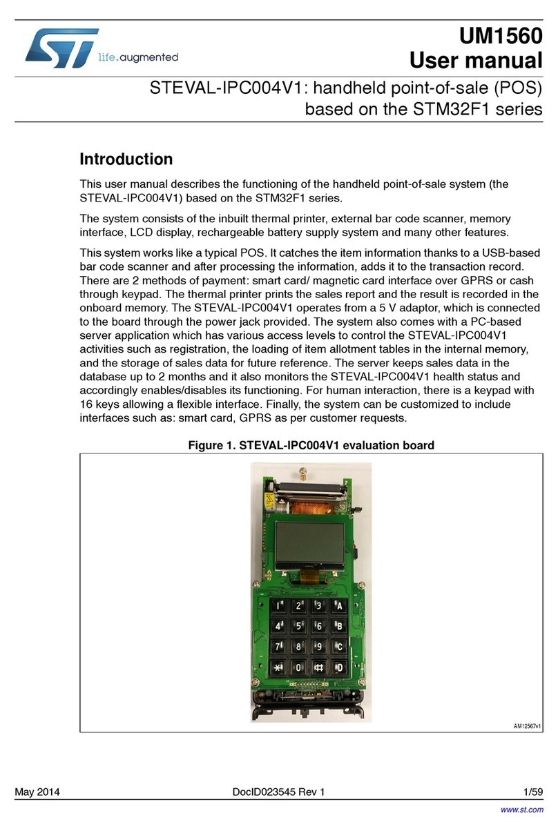
ST624xB-EMU2 - ST6 HDS2 NEW MAINFRAME EMULATOR
2.1 MAIN BOARD
The Main board controls the emulator thanks to a
ST9 central processing unit which executes com-
mands coming from host computer through the
parallel line.
The board contains all emulation resources, the
core of the ST6, the Program ROM emulation, the
break point logic, the trace memory, the automa-
ton and all necessary logic for a real time emula-
tion.
Two connectors, J1 and J2, are used to exchange
signals with the dedication board.
The amount ofprogram memory in the main board
is factory set at 32k, in fact the size of the memory
depends on the dedication board, which contains
the Program Rom Pagination Register (PRPR) if it
exists (no PRPR for memory size lower than 4k).
No configuration jumpers are required.
2.2 ST6 HDS2 MAIN BOARD
On the rear panel there is:
– a power plug to connect power: 5 Volts 3 Amp
min. (The delivered power is 100 volts to 240
volts input and 5 Amp output).
– a power switch.
– a parallel connector for an IBM PC(TM) compat-
ible.
On front panel:
– a led “POWER ON” signal.
– OUT 1 and OUT 2 signals which can be used for
synchronizing an external equipment.
– 2 leds indicating when the ST6 core is in “STOP”
or “WAIT” mode.
– a 16 pin connector for data acquisition signals.
The explanation of these signals is done in the
debugger manual.
2.2.1 External output: OUT1 and OUT2
For debugging hardware it is very useful to have
synchronization signals. The goal of the outputs 1
and 2 is to offer this feature to the user. They can
be programmed differently whether the debugger
used is the DOS debugger ST6NDB or the Source
Level Debugger WGDB6, as explained in the two
following paragraph. They are full programmable
with WGDB6.
Output OUT1 and OUT2 under ST6NDB
When using old DOS Version of debugger
ST6NDB:
This feature is programmable thanks to Hardware
Breakpoint Menu. The breakpoint MENU allows to
define breaking events. These events will gener-
ate an actual breakpoint only if break enable is
ON. When break is off, these events are existing in
the development tool. In the HDS2 emulator ver-
sion up to 4.3, the signals OUT1 and OUT2 are
connected to these internal breaking events.
Therefore these signals can be used to synchro-
nize an external device while running (breakpoint
off).
Output OUT1 and OUT2 under WGDB6
When using WGDB6 new Version of debugger at
source level under WindowsTM:
This feature is full programmable thanks to Hard-
ware Events/Trigger Menu. Output OUT1 and
OUT2 can be programmed in two ways:
– Events for synchronisation: it allows to the user
to preset pulses synchronisation for an external
equipment. The events can be defined by ad-
dresses or by range of addresses.
– Events for Timing Measure: it allows to the user
to measure time elapsed during a subroutine for
example. In this case, output OUT2 is SET on a
user defined address, and RESET on an other
one, OUT1 is the ST6 clock cycle gated by
OUT2.
These 2 functioning modes are clearly displayed
on screen.
10
