ST STEVAL-BLUEMIC-1 User manual

Introduction
The evaluation board comes with a complete SW development kit that includes the Bluetooth low energy stack, all the needed
drivers for audio and inertial data acquisition, and button and LED management. A ready-to-use BlueVoice library is included as
middleware and a sample application is provided to get you started with voice streaming over BLE to an Android or iOS device,
running the ST BlueMS apps.
The evaluation board mounts a transmitter module FCC (ID: S9NSPBTLE1S) certified and IC (IC: 8976C-SPBTLE1S) certified.
This BLE wireless battery powered solution also embeds digital MEMS microphone MP34DT05-A (or MP34DT04-C1 in the first
generation board) and 3D accelerometer + 3D gyroscope, which render this evaluation board suitable for a wide range of
advanced smart application.
The STEVAL-BLUEMIC-1 evaluation board mounts the SPBTLE-1S Bluetooth® SMART application processor compliant with
BT specification v4.2. It supports multiple simultaneous roles and can act as a Bluetooth Smart master and slave device at the
same time.
Figure 1. STEVAL-BLUEMIC-1 evaluation board
Getting started with the STEVAL-BLUEMIC-1 evaluation board, ultralow power
wireless microphone based on SPBTLE-1S module
UM2257
User manual
UM2257 - Rev 2 - February 2018
For further information contact your local STMicroelectronics sales office.
www.st.com/

1 Getting started
1.1 Hardware description
1.1.1 Features
• Bluetooth® SMART small form factor board based on the SPBTLE-1S module, Bluetooth v4.2 compliant
• On-board SPBTLE-1S module, based on BlueNRG-1, Bluetooth low energy application processor system on
chip embedding an high performance:
– ultra-low power ARM® Cortex®-M0 32-bit core architecture
– Programmable embedded 160 KB Flash
– 24 KB embedded RAM with data retention
• On-board MP34DT05-A (or MP34DT04-C1 in the first generation board) digital MEMS microphone
• On-board LSM6DSL: MEMS 3D accelerometer (±2 / ±4 / ±8 / ±16 g) + 3D gyroscope ±125 / ±245 / ±500 /
±1000 / ±2000 dps)
• Voltage supply: 1V8 or 3V3
• Battery or USB powered
• On-board STBC08 linear Li-Ion battery charger
• SWD connector
• Included in the development kit package:
–STEVAL-BLUEMIC-1
– Plastic box for housing STEVAL-BLUEMIC-1
– 100 mAh Li-Ion battery
– SWD programming cable
• SW development kit for audio and inertial MEMS data streaming over BLE
• ST BlueMS: Android and iOS demo App available in the respective stores
1.1.2 Evaluation kit
The STEVAL-BLUEMIC-1 evaluation kit helps you to start prototyping a very low power solution to stream audio
and inertial data over BLE, exploiting the single-mode system-on-chip BlueNRG-1.
Figure 2. STEVAL-BLUEMIC-1 evaluation kit
The evaluation kit contains:
• an STEVAL-BLUEMIC-1 evaluation board
UM2257
Getting started
UM2257 - Rev 2 page 2/35

Figure 3. STEVAL-BLUEMIC-1 evaluation board: top and bottom
• a 100 mAh LiPO battery to be connected to the evaluation board as power supply
Figure 4. Battery
• a plastic case to house the evaluation board connected to the battery
Figure 5. Plastic case
• an ST-LINK SWD programming cable to program the evaluation board connected to ST-LINK
Figure 6. SWD cable
1.1.3 Evaluation board
The STEVAL-BLUEMIC-1 evaluation board is a highly integrated reference design that enables a fast prototyping
of very low power solutions for audio and inertial streaming.
UM2257
Hardware description
UM2257 - Rev 2 page 3/35

Figure 7. STEVAL-BLUEMIC-1 evaluation board hardware architecture
Figure 8. STEVAL-BLUEMIC-1 evaluation board main components
Table 1. STEVAL-BLUEMIC-1 evaluation board main component details
Reference Device Description
ASPBTLE-1S Bluetooth Low Energy application processor compliant with BT specification v4.2, based on
BlueNRG-1 system-on-chip
BLSM6DSL iNEMO inertial module: low-power 3D accelerometer and 3D gyroscope
CMP34DT05-A MEMS audio sensor digital microphone (MP34DT04-C1 in the first generation board)
D Button User button
E LED A blue LED and a green LED for visual feedback
F USB Micro USB connector for power supply and battery charging
G Battery connector Connector to plug the LiPO battery contained in the kit
H Switch ON-OFF switch to power the board
I SWD connector 5-pin SWD connector for programming and debugging
UM2257
Hardware description
UM2257 - Rev 2 page 4/35

1.1.4 Schematic diagrams
Figure 9. Power and SPBTLE-1S module
Battery Charger
BlueNRG-1 Module Footprint
USB, SWD, Battery monitor
Max 200mA
Vout=3V3
R1=147K R2=47K
Vout=1V8
R1=150K R2=120K
Battery monitor
(4.2V -> 1.8V)
VPROG = 1V
IBAT=(VPROG/RPROG)x1000
RPROG=1000*VPROG/IBAT
V_USB
VBlue
VBat
VBlue VBlue
VBlue
V_USB
V_USB
VBat
VBat
VBat VBat
V_USB VBat
I2C_SDA
I2C_SCL
INT1_AG
INT2_AG
PDM_CLK
PDM_DATA
LED1
LED2
BUTTON1
BATT1
Battery Connector
1
2
3
C2
4.7uF
VBAT
VBAT
1
C1
4.7uF
R13
20K
R2
47K
R16
0R
R15
NC
GND
GND
1
USB
USB-MICRO
1
2
3
4
SH1
SH2
5C7
4.7µF
R14
2K
SW1
PWR
R5
4K7
R11
140K
CHRG
2 1
SWD
1
2
3
4
5
U2 LDK120M-R
EN
3
GND
2
IN
1
ADJ 4
OUT 5
R12
105K
U1 STBC08PMR
PROG 5
CHRG
3
PAD 7
BAT 1
Vcc
6
GND 4
PWR_ON
2
C9
4.7µF
C8
100nF
R1
147K
U3 SPBTLE-1S
DIO14/ANATEST0 6
VBLUE
5DIO5/I2C_SDA
4DIO4/I2C_CLK
3ADC IN1
2ADC IN2
1
DIO6/UART_RTS 9
DIO7/BOOT/UART_CTS 7
DIO8/UART_TXD 10
DIO11/UART_RXD 11
DIO9/TCK/SWTCK 12
DIO10/TMS/SWTDI 13
ANATEST1 14
DIO0/SPI_CLK 15
DIO2/SPI_MOSI 16
DIO1/SPI_CS 18
BT_RESET 19
DIOA12 20
DIO3/SPI_MISO 17
GND 8
R8
0R
SWDIO
RESET
SWDCLK
SWDCLK
RESET
SWDIO
ADC_IN2
ADC_IN2
CHRG
CHRG
UM2257
Hardware description
UM2257 - Rev 2 page 5/35

Figure 10. MEMS, button and LEDs
VBlue
VBlue
VBlue
VBlue
VBlue
VBlue
VBlue
PDM_CLK
I2C_SCL
I2C_SDA
INT1_AG
INT2_AG
PDM_DATA
I2C_SCL
I2C_SDA
BUTTON1
LED1
LED2
R7
100K
R3
4K7
M1 MP34DT05-A
DOUT 4
LR 2
GND 5A
VDD
1
CLK
3
GND 5B
GND 5D
GND 5C
R10
100
R9 1K
R4 1K
C6
10nF
C4
100nF
R6
4K7
C3
100nF
Button1
12
3
4
5
6
U4
LSM6DSL
GND1 6
VDDIO 5
INT1
4SCx
3SDx
2SDO/SA0
1
VDD 8
INT2 9
OCS_Aux 10
SDO_Aux 11
CS
12
SCL
13 GND2 7
SDA
14
C5
100nF
LED2
LED Blue
2 1
LED1
LED Green
2 1
UM2257
Hardware description
UM2257 - Rev 2 page 6/35

1.2 Software description
1.2.1 Overview
The STSW-BLUEMIC-1 is an evaluation software package that allows development of smart and innovative
solution using the SPBTLE-1S module.
The software package includes the entire Bluetooth® low energy stack and protocols, complaint with the STSW-
BLUENRG1-DK. It also contains a Board Support Package that offers a complete set of APIs for digital MEMS
microphone, 3-axis accelerometer and gyroscope, button and LED management.
The latter is based on BlueNRG-1, a very low power Bluetooth low energy single mode system-on-chip
embedding a high performance, ultra-low power 32-bit ARM® Cortex®-M0, with 160 kB of Flash memory and 24
kB of RAM.
The BlueVoiceADPCM_BNRG1 binary library (available as middleware) provides a vendor specific profile for
voice streaming over Bluetooth® low energy; it includes all APIs needed for audio compression using the ITU-T
G.726 ADPCM standard, packetization and streaming.
The STSW-BLUEMIC-1 allows an STEVAL-BLUEMIC-1 evaluation board to act as a peripheral in a point-to-point
connection with a mobile device running the ST BlueMS app, available for Android™ and iOS™. In this
configuration, the evaluation board streams the audio acquired from the on-board digital MEMS microphone
(MP34DT05-A or MP34DT04-C1) or motion data acquired from the 3-axis accelerometer and gyroscope
(LSM6DSL).
1.2.2 Architecture
The STSW-BLUEMIC-1 software is organized in different layers.
Figure 11. STSW-BLUEMIC-1 software architecture
The application layer manages the complete software chain from the audio and inertial data acquisition to the
streaming.
A complete set of drivers is available to interact with the on-board sensors and to manage the BlueNRG-1
peripheral.
A middleware layer, between the application and the hardware abstraction layer, includes:
• the Bluetooth® Low Energy stack library that allows communication between the central and the peripheral
device;
• the BlueVoiceADPCM_BNRG1 library that provides all the APIs needed to implement a voice-over-
Bluetooth® Low Energy profile.
UM2257
Software description
UM2257 - Rev 2 page 7/35

1.2.3 Folder structure
Figure 12. STSW-BLUEMIC-1 folder structure
The following folders are included in the software package:
•Binary: contains ready-to-use firmware binary to be flashed on the STEVAL-BLUEMIC-1 evaluation board
•Documentation: contains a compiled HTML file generated from the source code detailing the software
components and APIs
•Drivers: contains the board specific drivers including the on-board components
•Library: contains the Bluetooth low energy stack binary library, the CMSIS vendor-independent hardware
abstraction layer for the ARM®Cortex®-M processor series, and BlueNRG-1 peripheral drivers
•Middlewares: contains the BlueVoice over BlueNRG-1 library
•Projects: contains demo applications for voice transmission over Bluetooth Low Energy. The projects
support IAR Embedded Workbench for ARM, RealView Microcontroller Development Kit (MDK-ARM) and
Atollic-True Studio for ARM development environments
1.2.4 APIs
Fully detailed user-API function and parameter descriptions are compiled in an HTML file located in the software
Documentation folder.
1.2.5 BlueMic1 application
The BlueMic1 application has been designed and built on the Bluetooth low energy architecture.
1.2.5.1 BlueMic1 profile description
The BlueMic1 application deploys a connection-based communication paradigm by providing a permanent point-
to-point link between two devices, one acting as peripheral and one as central (Generic Access Profile or GAP).
The STEVAL-BLUEMIC-1 evaluation board acts as a peripheral device supporting a single connection and low
complexity. This device only requires a controller that supports the slave role.
The central module can be an Android™ and iOS™ device running the ST BlueMS app (v3.0.0 or higher) or a FP-
AUD-BVLINK1 receiver node.
The central and peripheral role assignment reflects the asymmetric design concept of Bluetooth Low Energy,
where the device with a lower energy source works less: a slave cannot initiate complex procedures, whereas a
master manages communication timing, adaptive frequency hopping, encryption setup, etc. A portable device
provided with a coin-size battery is usually suitable as slave device.
Data sent through a Bluetooth Low Energy connection is organized through an additional protocol layer, the
Generic Attribute Profile (GATT). It provides standard profiles to ensure interoperability between devices from
different vendors that implement features like Proximity Profile, Glucose Profile and Health Thermometer Profile.
The Bluetooth specification also lets you add custom profiles.
GATT defines client and server roles for interacting devices independent of the GAP master/central and slave/
peripheral roles:
•Client performs service discovery about the presence and nature of server attributes; it sends requests to a
server and accepts responses and server-initiated updates.
•Server accepts requests, commands and confirmations from a client and sends responses and server-
initiated updates; it arranges and stores data according to the attribute (ATT) protocol.
UM2257
Software description
UM2257 - Rev 2 page 8/35

In a mono-directional audio streaming asymmetric system, the device with voice data is the one with a
microphone and is therefore considered the server. The client device sends requests to the server and accepts
server-initiated updates containing audio data.
Audio data transmission is based on periodic server-to-client notifications which do not require a request or
response from the receiving device. Server-initiated updates are sent as asynchronous notification packets which
include the handle of a characteristic along with its current value.
According to the Bluetooth specification, the peripheral enters advertising mode at start-up and sends
advertisement packets at relatively long intervals. The central unit enters discovery mode and sends a connection
request on reception of an advertisement packet from a slave device. After connection, notifications carrying
audio data are periodically sent from the server to the client.
1.2.5.2 BlueMic1 service
The Attribute Protocol (ATT) is used by GATT as a transport protocol for exchanging data between devices. The
smallest entities defined by ATT (named attributes) are addressable pieces of information that may contain user
data or meta-information on the attribute architecture, stored in the server and exchanged between client and
server.
GATT server attributes are organized as a sequence of services, each one starting with a service declaration
attribute marking its beginning. Each service groups one or more characteristics and each characteristic can
include zero or more descriptors.
Since audio streaming is not part of the predefined set of profiles, the STSW-BLUEMIC-1 application defines a
vendor-specific service named BlueMic1 Service based on an Audio characteristic to expose actual compressed
audio data and a Sync characteristic to expose collateral information to implement a synchronization mechanism
and an inertial characteristic to expose 3-axis accelerometer and gyroscope raw data.
Table 2. BlueMic1 UUID summary table
UUID name UUID
bluemic1_service_uuid 00000000-0001-11e1-9ab4-0002a5d5c51b
audio_adpcm_char_uuid 08000000-0001-11e1-ac36-0002a5d5c51b
audio_adpcm_sync_char_uuid 40000000-0001-11e1-ac36-0002a5d5c51b
acc_gyr_char_uuid 00E00000-0001-11e1-ac36-0002a5d5c51b
Given the service hierarchical architecture, further characteristics may be added to the BlueMic1 service, such as
configuration of parameters like volume, enabling/disabling of processing algorithms, etc.
1.2.6 Audio processing
The audio processing component of the STSW-BLUEMIC-1 application is designed to achieve an audio sampling
frequency of 8 or 16 kHz at the receiver side, with a trade-off between audio quality and bandwidth occupation for
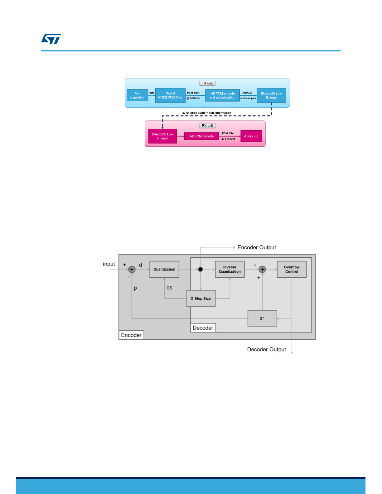
voice signals. The audio signal transmitted is compressed via ADPCM (adaptive differential pulse code
modulation) to fit in the available data rate while minimizing radio transmission time and power consumption.
The figure below shows the speech processing chain in a complete communication system with Tx and Rx.
On the Tx side, the library receives an audio signal which is typically acquired by a digital MEMS microphone as a
1-bit PDM signal and converted by a PDM to PCM conversion filter, integrated in the ADC peripheral of the
BlueNRG-1 SoC, into 16-bit PCM samples at 8 or 16 kHz.
The library can be provided with 1, 2, 5 or 10 ms of audio data. When the compressed output buffer is ready, a
flag is set and audio data is streamed via Bluetooth Low Energy together with collateral ADPCM information. The
resulting communication bandwidth is 32 kbps (with 8 kHz audio sampling frequency) or 64 kbps (with 16 kHz
audio sampling frequency) of audio data plus 300 bps of collateral information.
UM2257
Software description
UM2257 - Rev 2 page 9/35

Figure 13. STSW-BLUEMIC-1 audio processing chain
1.2.7 ADPCM compression
The ITU-T G.726 adaptive differential pulse code modulation (ADPCM) standard is applied to save bandwidth.
This audio algorithm for lossy waveform coding predicts the current signal value from previous values, and
transmits the difference between the real and the predicted value, quantized with an adaptive quantization step.
The ADPCM algorithm used in this application compresses digital voice signals encoded as:
• Audio format: PCM
• Audio sample size: 16 bits
• Channels: 1 (mono)
• Audio sample rate: 8-16 kHz
Figure 14. ADPCM encode-decode schema
BlueVoiceADPCM implements a modified version of the compression algorithm with improved communication
robustness through an additional low data rate channel with collateral information added to the ADPCM quantized
values; slightly increasing the overall bit-rate to an average 64.3 Kbps.
The internal buffering required by ADPCM compression is shown in the figure below. 16-bit input PCM samples
are encoded in 8-bit temporary samples with 4-bit actual data (u8 ADPCM_app buffer) and then encapsulated in
8-bit samples containing information of two PCM samples (u8 ADPCM buffer).
UM2257
Software description
UM2257 - Rev 2 page 10/35

Figure 15. ADPCM packet mechanism
ADCPM decoding on the Rx side is performed in a symmetric fashion.
1.2.8 Packetization
The Tx data rate for streaming data is obtained from:
• the connection interval
• the number of packets per connection interval and user data payload for each packet
The STSW-BLUEMIC-1 application implements:
• a constant bitrate allocated to audio data through the chosen ADPCM compression
• a small connection interval to minimize the overall audio latency
The following connection intervals are set for Android™ and iOS™ compliance:
• conn_min_int=10 ms
• conn_max_int=21.25 ms
If the streaming is performed between two ST modules, the selected connection interval is the minimum value (10
ms). The target 64 kbps constant data rate is achieved by sending 80 bytes of ADPCM data (640 bits) at each
connection event. Consistent with maxPayload = 20 bytes per packet (160 bit), four packets (two if an audio
sampling frequency of 8 kHz is set) of 20 bytes are sent per average connection event. In addition, ADPCM
collateral information is sent at a lower frequency via an additional smaller packet sent at regular intervals.
The following figure shows a 16 kHz compressed audio streaming example, where four data packets of 20 bytes
are sent at each connection interval of 10 ms, while ADPCM collateral information is sent as an additional packet
once every 160 ms.
UM2257
Software description
UM2257 - Rev 2 page 11/35

Figure 16. BLE packets for 16 Hz audio
1.2.9 STSW-BLUEMIC-1 application description
The STSW-BLUEMIC-1 software package is a complete example of audio and inertial data streaming over
Bluetooth® Low Energy to an Android™ and iOS™ mobile device running the ST BlueMS app or to an STM32
platform.
Figure 17. STSW-BLUEMIC-1 software package architecture
The main loop continuously calls the BTLE_StackTick function needed for the RF management and the APP_T
ick that contains all the functions implemented by the user.
As soon as the application starts, the APP_STATUS_ADVERTISEMENT state is set, BlueNRG-1 acts as a
peripheral and sends advertisement messages until a central node requests a connection.
When the connection is estabilished, the app status is set to APP_STATUS_CONNECTED and two different demos
can be activated from the ST BlueMS app running on the central node.
If BlueVoice is enabled (firmware status set to APP_BLUEVOICE_ENABLED) audio acquisition from the on-board
digital microphone starts and drives the voice streaming. PCM samples are compressed and sent.
The audio streaming can be stopped or restarted by pressing the STEVAL-BLUEMIC-1 evaluation board button.
The user can switch to the inertial demo (firmware status set to APP_INERTIAL_ENABLE) via the BlueMS app.
A timer is set and every 30 ms raw data are acquired from the 3-axis accelerometer and gyroscope and sent to
the mobile device together with a timestamp increased by one every 10 ms.
UM2257
Software description
UM2257 - Rev 2 page 12/35

1.3 BlueVoiceADPCM_BNRG1 library software description
1.3.1 Initialization and configuration
To initialize the library call the BluevoiceADPCM_BNRG1_Initialize API. Then, configure the library on the
basis of the audio acquisition implemented in the application.
A configuration structure must be filled by setting the audio sampling frequency (FR_8000 or FR_16000), the total
number of channels given as the input to the library and which channel (between 1 and channel_tot) is used for
the voice streaming:
BV_ADPCM_BNRG1_Config_t BV_ADPCM_BNRG1_Config;
BV_ADPCM_BNRG1_Config.sampling_frequency = FR_8000;
BV_ADPCM_BNRG1_Config.channel_in = 1;
BV_ADPCM_BNRG1_Config.channel_tot = 1;
BluevoiceADPCM_BNRG1_SetConfig(&BV_ADPCM_BNRG1_Config);
If the return value is BV_ADPCM_BNRG1_SUCCESS, the library has been correctly configured.
The BlueVoiceADPCM_BNRG1 library can be reset by recalling BluevoiceADPCM_BNRG1_SetConfig.
The library includes three callbacks that must be called when the corresponding BlueNRG event occurs:
•BluevoiceADPCM_BNRG1_ConnectionComplete_CB sets the connection handle when an
EVT_LE_CONN_COMPLETE event occurs;
•BluevoiceADPCM_BNRG1_DisconnectionComplete_CB resets internal parameters when an
EVT_DISCONN_COMPLETE event occurs;
•BluevoiceADPCM_BNRG1_AttributeModified_CB sets the working mode according to the enable
notification received when an EVT_BLUE_GATT_ATTRIBUTE_MODIFIED event occurs.
A timeout has been included for correct management of the BlueVoice profile status; when the module is no
longer streaming or receiving, the profile status switches to BV_ADPCM_BNRG1_STATUS_READY as soon as the
timer expires. The timeout duration (in ms) is defined by BV_ADPCM_BNRG1_TIMEOUT_STATUS.
To increase this timer, call the BluevoiceADPCM_BNRG1_IncTick function every 1 ms from the
SysTick_Handler.
1.3.2 Working mode setup
The library working mode can be configured as NOT_READY (initial setting), TRANSMITTER, RECEIVER or
HALF-DUPLEX.
The service and characteristics for the BlueVoice profile can be created by calling the BluevoiceADPCM_BNRG1
_AddService and BluevoiceADPCM_BNRG1_AddChar functions.
Both APIs require the UUIDs (chosen by the user) as parameters and they return the relevant handle.
The handle of the service must be passed to the BluevoiceADPCM_AddChar API.
Alternately, BlueVoice characteristics can be added to a pre-existing service created in your own application by
calling BluevoiceADPCM_BNRG1_AddChar and passing the handle of that particular service as a parameter.
If both the functions return BV_ADPCM_BNRG1_SUCCESS, the library is set to TRANSMITTER mode and can
stream audio over Bluetooth Low Energy.
You can also create the characteristics out of the library and pass the relevant handles using a structure of the
type BV_ADPCM_BNRG1_ProfileHandle_t to the BluevoiceADPCM_BNRG1_SetTxHandle API. In the latter
case, the following characteristics must be created:
• related to the compressed audio data
aci_gatt_add_char(ServiceHandle,
UUID_TYPE_128, CharAudioUUID, 20,
CHAR_PROP_NOTIFY, ATTR_PERMISSION_NONE,
GATT_DONT_NOTIFY_EVENTS, 16, 1,
CharAudioHandle);
UM2257
BlueVoiceADPCM_BNRG1 library software description
UM2257 - Rev 2 page 13/35

• to send collateral information for synchronization mechanism implementation
aci_gatt_add_char(ServiceHandle,
UUID_TYPE_128, CharAudioSyncUUID, 6,
CHAR_PROP_NOTIFY, ATTR_PERMISSION_NONE,
GATT_DONT_NOTIFY_EVENTS, 16, 1,
CharAudioSyncHandle);
You can choose to not create the BlueVoice Service and the module is not able to transmit audio.
This node can still function as a RECEIVER; however, if the connected module exports the BlueVoice profile; you
must set the handle of the BlueVoice service and characteristics exported by the transmitter module through the B
luevoiceADPCM_BNRG1_SetRxHandle API and enable notifications on the other node by calling the Bluevoi
ceADPCM_BNRG1_EnableNotification function.
If both the TRANSMITTER and RECEIVER procedures are performed, the module acts as transmitter and
receiver and the working mode is set to HALF-DUPLEX, creating a half-duplex link over Bluetooth Low Energy.
1.3.3 Audio signal injection
The BlueVoiceADPCM_BNRG1 library receives audio PCM input samples.
The BluevoiceADPCM_BNRG1_AudioIn function accepts parameters from a PCM buffer, containing all the
acquired audio channels (channel_tot according to the previous library configuration) and the number of PCM
samples (for each channel) given as input. An amount of data equal to 1, 2, 5 or 10 ms is accepted, otherwise an
BV_ADPCM_BNRG1_PCM_SAMPLES_ERR is returned.
The library compresses received PCM input samples; when 10 ms of audio is compressed, the BluevoiceADPC
M_BNRG1_AudioIn API returns BV_ADPCM_BNRG1_OUT_BUF_READY.
1.3.4 Compressed audio streaming
On the transmitter side, the BlueVoiceADPCM_BNRG1 library gathers compressed data in an internal double
buffer. For every 10 ms of audio, the BluevoiceADPCM_BNRG1_AudioIn function returns BV_ADPCM_BNRG1_O
UT_BUF_READY to signal output data can be send via Bluetooth Low Energy by calling the BluevoiceADPCM_B
NRG1_SendData API.
If the audio sampling frequency is set to 8 kHz, two 20-byte packets are sent every 10 ms (according to the
connection interval); if the frequency is 16 kHz, four 20-byte packets are sent.
On the receiver side, compressed audio is received from a notification through a
EVT_BLUE_GATT_NOTIFICATION event and passed to the BluevoiceADPCM_BNRG1_ParseData function
that decompresses the data and returns a PCM buffer. This API is used to parse both audio and collateral
information data.
UM2257
BlueVoiceADPCM_BNRG1 library software description
UM2257 - Rev 2 page 14/35

2 System setup
Two types of demos can be set up using an STEVAL-BLUEMIC-1 evaluation board:
1. unidirectional streaming of inertial data and audio at a sampling frequency of 8 kHz from the STEVAL-
BLUEMIC-1 to an Android™ or iOS™ device running the ST BlueMS app (v3.0.0 or higher);
2. unidirectional audio streaming at a sampling frequency of 8 or 16 kHz from the STEVAL-BLUEMIC-1 to the
receiver node of the FP-AUD-BVLINK1 application available on www.st.com.
2.1 Power supply
The main board power supply is the 100 mAh lithium-Ion polymer battery plugged to the connector on the PCB.
Figure 18. Battery connection and power switch
Use SW1 switch to power the STEVAL-BLUEMIC-1 evaluation board on or off.
The battery can be recharged via USB connected to a PC or any micro-USB battery charger. A red LED indicates
the charging status:
• steady ON: the board is charging
• steady OFF: charge complete
The on-board voltage regulator provides a 3.3 V power supply that can be changed to 1.8 V by replacing R1 and
R2 according to the board schematic diagram (see Section 1.1.4 Schematic diagrams).
The STEVAL-BLUEMIC-1 can be powered using only the USB connector; the battery must be unplugged and the
battery charger must be bypassed by removing R8 e by soldering the R15 0 Ohm resistor.
2.2 STEVAL-BLUEMIC-1 evaluation board assembly in form factor case
The STEVAL-BLUEMIC-1 evaluation board connected to the battery can be housed in the plastic box included in
the evaluation kit as shown below.
UM2257
System setup
UM2257 - Rev 2 page 15/35

Figure 19. STEVAL-BLUEMIC-1 evaluation board in plastic case
2.3 STEVAL-BLUEMIC-1 evaluation board programming interface
To program the board, connect an external ST-LINK to the SWD connector on the STEVAL-BLUEMIC-1
evaluation board; a 5-pin flat cable is provided in the evaluation kit.
The easiest way to obtain an ST-LINK device is to get an STM32 Nucleo board, which bundles an ST-LINK V2.1
debugger and programmer.
1. Ensure that CN2 jumpers are OFF and connect your STM32 Nucleo board to the STEVAL-BLUEMIC-1
evaluation board via the cable provided, paying attention to the polarity of the connectors
Pin 1 is identified by:
– a small dot on the PCB silkscreen on the STM32 Nucleo board
– the square shape of the soldering pad on the STEVAL-BLUEMIC-1 evaluation board
2. Download from ST website the "BlueNRG-1 ST-LINK utility", a full-featured software interface to program the
BlueNRG-1 microcontroller.
3. Follow the installation procedure
4. Program the STEVAL-BLUEMIC-1 evaluation board with the demo binary available in the software package.
UM2257
STEVAL-BLUEMIC-1 evaluation board programming interface
UM2257 - Rev 2 page 16/35

Figure 20. STM32 Nucleo board and STEVAL-BLUEMIC-1 SWD connections with a 5-pin flat cable
2.4 STEVAL-BLUEMIC-1 evaluation board demos
2.4.1 Streaming to a mobile device
One of the possible demos to be performed using a STEVAL-BLUEMIC-1 evaluation board is the unidirectional
streaming from the board to an Android™ or iOS™ device running the ST BlueMS app (v3.0.0 or higher).
Set up the STEVAL-BLUEMIC-1 evaluation board as explained in the previous sections and program it with the
relevant binary file (STSW-BLUEMIC1_8kHz.bin) included in the software package.
In this configuration, a point-to-point connection is created between the STEVAL-BLUEMIC-1 evaluation board
acting as a peripheral and a mobile device acting as a central device: as soon as the two systems are connected,
the evaluation board streams audio (acquired from the on-board microphone at 8 kHz of sampling frequency) or
inertial raw data (acquired from the 3-axis accelerometer and gyroscope).
UM2257
STEVAL-BLUEMIC-1 evaluation board demos
UM2257 - Rev 2 page 17/35

Figure 21. Voice streaming from the STEVAL-BLUEMIC-1 evaluation board to an Android™ or iOS™
mobile device
2.4.1.1 ST BlueMS app
To run this demo:
1. Turn the STEVAL-BLUEMIC-1 evaluation board on via SW1 switch
2. Open the ST BlueMS app on your smartphone or tablet.
Note: Android app screenshots are used to show how the app works, but the procedure is the same for the iOS app.
3. Start the scanning procedure when the app is ready
4. Wait until BVBNRG1 appears in the device list
If it does not appear, clear the device cache from the upper right corner menu.
5. When the scan finishes, select the device to be connect to.
The application switches to the demo view and starts the connection procedure.
Figure 22. BlueMS (Android version) app device list
UM2257
STEVAL-BLUEMIC-1 evaluation board demos
UM2257 - Rev 2 page 18/35

2.4.1.2 BlueVoice page
When the STEVAL-BLUEMIC-1 evaluation board is connected to a mobile device the on-board green LED turns
on and the board starts streaming audio to the mobile device (in this phase the blue LED starts blinking fast).
Note: In a different version of the evaluation board the color of the LED can be inverted.
You can stop and restart the streaming by pressing the button on the evaluation board.
The volume can be adjusted (via the slider on the BlueVoice page) or muted (by clicking on the speaker icon).
Figure 23. BlueMS (Android version) BlueVoice demo
2.4.1.2.1 ASR language selection
Opening the ASR language menu, located in the demo main menu, the application displays a popup window that
allows the ASR language selection.
According to the language selected, a specific ASR service is configured which determines the application
behavior.
UM2257
STEVAL-BLUEMIC-1 evaluation board demos
UM2257 - Rev 2 page 19/35

Figure 24. BlueMS (Android version) ASR language selection
2.4.1.2.2 Chinese ASR: iFlyTek MSC service
When Chinese is selected, the ASR service provided by iFlyTek is enabled.
Pushing the button on the bottom right hand of the screen, it becomes green and the speech-to-text service
starts.
The recognition is continuous and every sentence is recorded as shown below.
UM2257
STEVAL-BLUEMIC-1 evaluation board demos
UM2257 - Rev 2 page 20/35
Other manuals for STEVAL-BLUEMIC-1
1
Table of contents
Other ST Motherboard manuals

ST
ST STEVAL-BLUEPLUG1 User manual

ST
ST STM32L4 Series User manual

ST
ST EVAL-RHRICL1ATV1 User manual

ST
ST STM32439I-EVAL User manual

ST
ST STM32L5 Nucleo-144 board User manual

ST
ST PowerSTEP01 EVLPOWERSTEP01 User manual

ST
ST AEKD-AICAR1 User manual

ST
ST STEVAL-ISC004V1 User manual

ST
ST STM32H7 Nucleo-144 User manual

ST
ST EVAL-L9177A User manual

ST
ST SPC572L-DISP User manual

ST
ST SPC58XXADPT144S REV.B User manual

ST
ST STM32H735G-DK User manual

ST
ST STEVAL-LVLP01 User manual

ST
ST STM32CubeF4 User manual

ST
ST STEVAL-ISB044V1 User manual

ST
ST UM0920 User manual

ST
ST B-L4S5I-IOT01A User manual

ST
ST SPC58NG-DISP User manual

ST
ST AEKD-USBTYPEC1 User manual