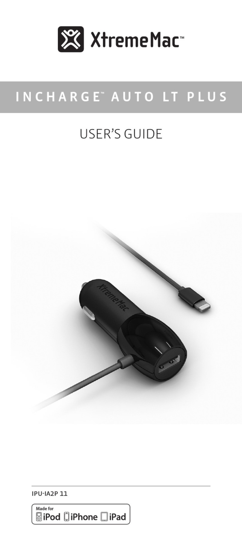
Stack ST700 User manual

200227-001
Quartz
kRPM
Model ST700 Dash
Display System
ST542059–001

1. Install the ST700 Dash Display System and connect it to
the switched battery circuit, for example the ignition (B+)
and the battery negative (B–).
2. Install and connect the controls (following the instruc-
tions that start on page 13).
3. Connect the ST700 Dash Display System ‘ES’ wire to the
ignition low tension circuit.
4. Connect the sensors supplied with your system.
5. Turn on the ignition.
6. Use the Demonstration Mode to check that the ST700
Dash Display System is functioning normally.
7. Take the ST700 Dash Display System out of its demon-
stration mode by changing the setting for the number of
cylinders. See page 53 for instructions.
8. Use the Driver button to select the display layers
described on page 32.
9. Use the Rotary control to select the Memory Review and
Setup modes as described on page 44.
10.Use the rotary control to set up the ST700 Dash Display
System.
QuickStart


ST700 Dash Display System Contents
© Stack 1
CONTENTS
CONTENTS 1
INTRODUCTION 3
How to use this manual 5
Safety Issues 6
Unpacking and Inspection 7
INSTALLATION 8
Product Installation 8
Wiring Harness 9
ST700 Dash Display System Display 12
Controls 13
Engine Speed Measurement 14
Lap Timing Sensor option 16
Trackside I.R. Beacon (optional) 18
Manual Lap Timing (optional) 20
Wheel Speed Sensor 21
Pressure Sensor options 23
Oil pressure switch 25
Temperature Sensor options 25
Battery connection 27
OPERATION 28
Switch functions 28

Contents ST700 Dash Display System
2
Power–on the ST700 Dash Display System 31
Changing the display layers 32
Lap and Split Times 37
Manual Split Timing Setup 39
Automatic Split Timing Setup 41
Hillclimb and Sprint Operation 42
MEMORY AND SETUP 43
Memory review features 44
Setup mode 47
TESTING 60
MAINTENANCE 62
Troubleshooting 62
Specification 72
Contact details 75
INDEX 79

ST700 Dash Display System Introduction
© Stack 3
INTRODUCTION
Thank you for selecting the ST700 Dash Display System from Stack as
your choice of vehicle's instrumentation—we feel sure that you are go-
ing to be delighted by your purchase!
The ST700 Dash Display System is a superb quality instrument that in-
tegrates a number of performance functions into a single display prod-
uct. The functions enabled on your unit are specific to your selection.
However, any ST700 Dash Display System can be upgraded to include
any combination of the available functions.
Functions on all ST700 Dash Display Systems:
❑Engine RPM—with maximum RPM telltale
❑Any two of pressure and temperature sensors
❑Vo l t m et e r g a u g e s
❑Vehicle speed (user–selectable MPH or km/h)
❑Peak value recall and intelligent alarm on all monitored engine
parameters
❑Adjustable backlighting intensity
❑Programmable sequential shift lights with four selectable patterns
and adjustable brightness
❑User– configurable setting to suit most vehicles

Introduction ST700 Dash Display System
4
Optional functions available:
❑Odometer and tripmeter (user–selectable Miles or Kilometres)
❑Lap and split–time memory
❑Corner and maximum straight speed read-out
❑User selectable acceleration and deceleration timer and ¼ mile time
❑Plug–in lap timing and data acquisition options
❑White or black dial face options offering a choice of RPM scales with
optimised ranges
The ST700 Dash Display System requires a connection to the vehicle
battery supply, the engine ignition system and the various sensors fitted
to the vehicle to provide the full range of measurements.
If your ST700 Dash Display System includes the option to trigger lap
times automatically, you will also require a vehicle–mounted infrared
(IR) sensor and a track–side IR beacon.
Refer to the following section of this user guide for instructions to install
the ST700 Dash Display System.
Depending on the model you have chosen, your ST700 Dash Display
System might not include some of the features described in this user
guide.

ST700 Dash Display System Introduction
© Stack 5
How to use this manual
This manual tells you how to:
Install the ST700 Dash Display System display instrument and its wiring
harness
Install and connect the standard and optional sensors on a vehicle
Configure the ST700 Dash Display System for your vehicle
Operate and read the ST700 Dash Display System during and after a
run
Throughout this manual, you will see the following symbol:
These are special or important notes and tips that you should read
and understand.

Introduction ST700 Dash Display System
6
Safety Issues
You must take note of the following safety advice when you install the
ST700 Dash Display System on your vehicle:
Follow the instructions to attach all components of the system se-
curely to the vehicle so that they do not vibrate loose and fall off.
The wiring harness supplied with the ST700 Dash Display System
is certified for use in high temperature applications up to 105°C
(221°F). Do not substitute wires that have a lower temperature rat-
ing than this. Contact Stack for advice if you are in any doubt.
Route all wires and the wiring harness so they do not snag against
any moving parts of the vehicle.
Do not apply sharp bends or other severe stresses to the wiring
harness.
Avoid positioning the sensors or their wires close to any sources
of intense heat or vibration or close to the leads of the ignition HT
or fuel injection systems.
Use cable clips to secure the wiring harness.
Use suitable glands or grommets to protect the wiring harness
where it passes through vehicle bulkheads or panels.

ST700 Dash Display System Introduction
© Stack 7
Unpacking and Inspection
When you unpack your ST700 Dash Display System, check all the items
against the packing list.

Installation ST700 Dash Display System
8
INSTALLATION
You do not need complicated tools or special training to install the ST700
Dash Display System. To gain the benefits of using this quality instru-
ment all you need are a few basic workshop tools, the willingness to
read and follow these instructions carefully and the time to complete
each task in sequence.
Refer to the instructions between page 43 and page 59 for instruc-
tions to set up the ST700 Dash Display System display and alarm lim-
its specifically for your vehicle.
Product Installation
The installation process begins when you start to install the wiring har-
ness, the controls and the ST700 Dash Display System display. After you
have completed these tasks, you can fit and connect the options and
sensors included with your system. You may then connect the ST700
Dash Display System to the vehicle electrical supply.
You will need to cut a hole into the instrument panel to accept the ST700
Dash Display System instrument display. Choose a suitable position for
it:
❑Mount the ST700 Dash Display System display on the instrument
panel so that the driver can see it easily, looking either through or
over the steering wheel, as shown in Figure 1.

ST700 Dash Display System Installation
© Stack 9
Figure 1: ST700 Dash Display System
display location
❑Position the ST700 Dash Display
System display so that the driver
can see it either square on or
from a position slightly above.
Figure 2: Overall dimensions
❑Make certain there is suffi-
cient space behind the instru-
ment panel to accept the ST700
Dash Display System display.
Allow additional space so that
you may run and connect the
wiring harness without the
need to apply sharp bends to
the harness.
Figure 2 shows the overall dimensions of the ST700 Dash Display Sys-
tem display, which fits into a standard 80 mm diameter hole.
Wiring Harness
Stack supplies a wiring harness to connect the ST700 Dash Display Sys-
tem within the vehicle. If you find that the standard wiring harness is
unsuitable for installation on your particular vehicle, contact Stack or an

Installation ST700 Dash Display System
10
approved Stack agent for details of wiring harness extensions. Labels
identify each wire in the harness shown in Figure 3.
1. Identify all the relevant connectors of the wiring harness.
2. Plan the location of all the component parts of your ST700 Dash Dis-
play System and decide the best layout to use when you install the
wiring harness.
Note that your installation might not use all the cables that exist in the
harness. You should tie back and protect all unused connectors.
3. Begin at the instrument panel where you will install the ST700 Dash
Display System display. Lay the wiring harness into the vehicle,
with the cable branches running to their appropriate locations.
Allow sufficient slack in the harness so that you can connect it to the
ST700 Dash Display System before you insert the display into the
instrument panel.
You should route all cables to be no closer than 75 mm (3 inches) to
the ignition HT leads or the distributor cap. Do not run cables close to
sources of intense heat.
4. Fit cable glands to protect the cables where they pass through bulk-
heads or panels. This is particularly important when you pass cables
through carbon fibre partitions, which can wear through them eas-
ily.

ST700 Dash Display System Installation
© Stack 11
Figure 3: Electrical connections

Installation ST700 Dash Display System
12
ST700 Dash Display System Display
1. Connect the wiring harness to the ST700 Dash Display System dis-
play. There are two connection ports on the back of the display, but
you can insert the 8–way connector only into one of them. Do not
try to force the connector into the incorrect port. Tighten the lock-
ing collar by hand. The second, 6–way, port allows you to connect
the optional pressure and temperature sensors and an optional data
logger module.
Figure 4: Display mounting
2. Fit the ST700 Dash Display
System display into the
instrument panel using the
supplied O-ring.
3. Reach behind the instrument
panel and position the secur-
ing bracket as shown in Fig-
ure 4. Tighten the lock nuts to
fix the ST700 Dash Display
System display into position.

ST700 Dash Display System Installation
© Stack 13
Controls
The ST700 Dash Display System includes three controls:
❑Driver button—this is a normally–open spring–loaded switch that
closes when pressed and opens when released.
❑Rotary control—this is a combined push button and rotary selector.
❑Lap button (optional)—this is a normally–open spring–loaded
switch option that closes when pressed and opens when released.
For convenience, you should install the controls where the driver may
operate them easily. An ideal installation for the Driver button and for
the optional Lap button is on the steering wheel within easy reach of a
thumb.
Install the rotary control where it is possible to operate it conveniently
while viewing the ST700 Dash Display System display.
1. Drill holes or install brackets to support the controls in the locations
you have selected for them. The hole dimensions and tightening
torques are:
Rotary control: M7 clearance (7.2 mm diameter) with the control
tightened to 1.2 Nm (12 kgf.cm or 0.9 lbf.ft)
Driver button: 12.2 mm diameter with the control tightened to 1.5
Nm (15 kgf.cm or 1.1 lbf.ft)
2. Connect the correct cables of the harness to each control.

Installation ST700 Dash Display System
14
Engine Speed Measurement
This connection is dependent on your ignition system. You should
read these instructions carefully and make certain you have identified
the correct connection point before you begin.
To measure engine speed you must make the correct connections be-
tween the ST700 Dash Display System and the vehicle ignition system.
Contact Stack for advice if you have a complicated ignition system.
If you cannot use any of these engine speed connections, you may use
the optional Stack ST697 HT pick-up to get a signal from an ignition
lead.
Table 1: Connection to the ignition system
Ignition System Connection point (Orange wire)
Coil and Points Coil negative (Low tension)
HEI Systems Coil negative (Low tension)
Magneto (external or internal) Ground switch terminal (magneto
side)
MSD Tachometer output
Magneto CD (2-stroke) Use HT pick up (ST697)

ST700 Dash Display System Installation
© Stack 15
Standard contact breaker system
Connect the ‘ES’ wire of the harness to the negative contact breaker ter-
minal on the coil as shown in Figure 5.
Electronic ignition connection
Connect to the electronic ignition of the vehicle as indicated in Figure 6.
If your ST700 Dash Display System includes the Lap Timing sensor, the
Wheel Speed sensor or any pressure or temperature sensors, follow the
instructions between page 16 and page 27 to install them. Otherwise,
turn to page 27 for instructions to connect your ST700 Dash Display Sys-
tem to the switched battery circuit of your vehicle.
Figure 5: Standard contact breaker
connection
Figure 6: Connection to electronic ig-
nition
Battery +ve

Installation ST700 Dash Display System
16
Lap Timing Sensor option
The lap-timing sensor triggers the ST700 Dash Display System automat-
ically each time the vehicle passes the Stack infrared (IR) beacon at the
side of the track.
1. Choose a location on the vehicle for the lap-timing sensor:
Figure 7: Lap timing beacon
❑You must position the sensor
to be horizontal and square
to the vehicle axis.
❑It must have a clear view of
the trackside beacon, even
when you overtake or are
overtaken by other vehicles.
❑Do not mount the sensor
behind glass or Perspex.
❑The sensor must be at the
same height as the beacon.
As shown in Figure 8, you can
adjust the height of the beacon to achieve this condition.
Table of contents
Other Stack Automobile Accessories manuals

