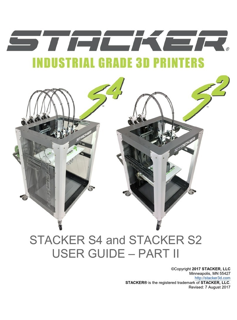
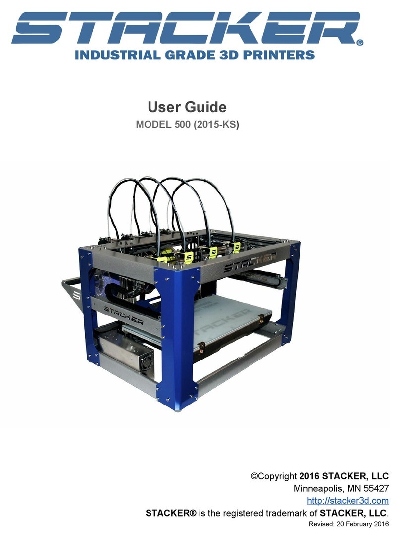
STACKER S Series User manual

Table of Contents
1. Warnings
2. Introduction
2.1 Product Registration
2.2. Software
2.3. Printer Specifications
3. Unboxing
3.1. ardware List
3.2. Final Printer Assembly
3.3. Uninterruptible Power Supply (UPS)
4. Your First Print
5. Changing Nozzles and Filament Guide Tube
5.1 Changing Nozzles
5.2 Changing Filament Guide Tubes
6. Printer Calibration
6.1 Adjusting First Layer eight
6.2 Stacker Run
6.3 Volumetric Calibration
6.4 S2 and S4 Bed Leveling
6.5 S4XL Bed Leveling
6.6 Leveling Nozzles
7. Filament Out Switch
8. Basic Printer Maintenance
8.1 Keep Your Printer Clean
8.2 Linear Guide Rails
8.3 Filament Drive Gears
8.4 Filament Guide Tubes
9. Terms and Conditions
Page 2

1. Warnings
Stacker 3D printers are industrial machines that should never be operated around children or left
unattended. Careful setup and training is required for optimal results. Read through this entire User
Guide and view online resources before attempting to operate your printer. Please note, this printed
copy of the User Guide may not be the most up to date version. We recommend downloading User
Guides from our website to confirm you have the most up to date version denoted by the last revision
date on the front cover of the User Guide.
Please read and take seriously all Warnings. Unsafe operation of a 3D printer can result in damage
to your printer and serious injury to yourself.
Burn Hazard! Do NOT touch hot surfaces!
Both the hot ends and heated bed can get OT! To prevent burns, avoid
touching the hot surfaces of the 3D printer.
Fire Hazard!
Never place flammable materials or liquids on or near the printer. It is your
responsibility to operate your printer in a safe manner. To ensure that it is safe,
you must incorporate the use of fire and smoke alarms and proper fire
suppression technologies like fire extinguishers. Never operate the printer
unattended.
aintain Clean Environment!
Operate printer in a clean environment. Avoid exposing printer to dirt, dust,
oil, smoke, or other environmental pollutants. The printer may not function
properly, and operational life will decrease, in an unclean environment.
Electric Shock Hazard!
The printer must be kept dry. Attempting to operate the printer in a wet
environment will damage your printer and could lead to injury. Always power down
and disconnect the power cable from your printer before servicing.
Static Charge Hazard!
Ground yourself before touching the printer. Static charge can damage your
printer's electronic components. Discharge your static before touching your printer!
Pinch Hazard! Keep Hands and Fingers Clear.
During operation, the printer will perform quick and unpredictable
movements. To avoid injury, never place your hands, fingers or body near any
moving parts of the printer including belts, pulleys, print bed, and hot ends. Be sure
to tie back long hair and remove any clothing or jewelry which could become
caught in the moving parts of the printer.
Age Warning.
For users under the age of 18, adult supervision is recommended. Printed parts
can be a choking hazard for small children. Never operate the printer unattended!
Page 3

2. Introduction
Welcome to STACKER! Our high performance industrial grade 3D printers are capable of producing
everything from one-off prototypes to multiple part production runs. To get the most out of your Stacker
3D printer, please read the entire User Guide before attempting to operate your printer. This User Guide
should provide all the information necessary to set up and operate your printer.
2.1 Product Registration
It is important to register your printer. In order to receive customer service support, warranty service, or
join our community forums, you must register your printer. Complete the registration form on our
website.
http://sta ker3d. om/produ t-registration/
During registration, you must enter your printer’s serial number. Your Stacker 3D printer has two serial
labels: one serial label is located inside the controller housing, and the second serial label is attached
to the inside of the front right leg.
2.2 Software
The 3D obje ts you will be printing are reated using two types of software, (1) omputer-aided design (CAD) software and (2)
sli ing software.
QUICK OVERVIEW OF SOFTWARE USE IN THE 3D PRINTING PROCESS
Design and Output: It is helpful to be familiar with solid modeling CAD applications in order to create
and manipulate the parts you want to 3D print. Often a simple design modification or splitting of a model
into multiple sections will allow you to print it faster, better, and without the need for support materials.
The following list of CAD software is by no means exhaustive, but these programs offer a good balance
of power and value, some of which are free and have robust online training and user communities.
Nearly all of these apps will export your models to the preferred STL file format.
▪SketchUp, Autodesk Meshmixer, Tinkercad
▪FreeCAD, openSCAD, Blender, 3D Builder
▪Autodesk Netfabb, Autodesk Fusion 360, C3D Toolkit, Geomagic Design, Alibre, Autodesk
AutoCAD
▪SolidWorks, Autodesk Inventor, Solid Edge
Page 4

Slice: In operating a 3D printer, it is most critical that you have a good understanding of your preferred
slicing engine before attempting your own prints. Slicing engines are used to convert an STL file into the
GCODE file, which operates the printer. A GCODE file provides the commands that enable the printer to
print a 3D object. We highly recommend Simplify3D. We have found Simplify3D to be one of the best
slicing engines available, we provide a license for a downloadable copy with your Stacker Printer and
have profiles for each Stacker model available on our website . To receive your copy of Simplify3D,
please be sure to register your printer and contact sales@
stacker3d.com
for your coupon code to
purchase your free copy of Simplify3D from our website. Slic3r and Cura do a good job and are free to
use.
The links below can help familiarize you with the operation of a slicing engine:
simplify3d.com/support/
Slic3r manual.slic3r.org
Cura support.ultimaker.com/hc/en-us/sections/360003548579-Getting-started
simplify3d.com/support/
Stacker RUN software is an enhanced version of Repetier Host customized for using Stacker printers.
Additional information and Stacker RUN software download is available on our website. You can find
additional documentation on the Repetier website.
Stacker RUN stacker3d.com/stacker-3d-printer-support/
http://www.repetier.com/#documantation
If you are interested in controlling your Stacker printer remotely, we recommend Repetier Server.
Through the combination of a Raspberry Pi and Repetier Server, you are able to operate your printer from
any web enabled device.
http://www.repetier-server.com
Page 5

2.3 Printer Specifications
Products S2 S4 S4XL
Number of Extruders 2 4 4
Build Volume 490mm (X),
390mm (Y),
650mm (Z)
520mm (X),
365mm (Y),
650mm (Z)
610mm (X),
610mm (Y),
610mm (Z)
Weight 140 kg (310 lbs) 140 kg (310 lbs) 163 kg (360 lbs)
Physical Dimensions 28.3” x 35.4” x 43.3” 28.3” x 35.4” x 43.3” 40.2” x 49.9” x 52.6”
Machine Type Cartesian
Firmware Repetier
Motor Stepper Servo
Print Speed 1 – 250 mm/sec
X/Y Movement
Speed 1 – 250 mm/sec
Positional Accuracy
X/Y 6 Microns
Positional Accuracy
Z4 Microns
Layer eight 0.1 to 1mm
Extruder
Temperature Up to 300°C
eated Bed
Temperature Up to 110°C
Standard Nozzle
Size 0.4mm
Optional Nozzle Size 0.25mm, 0.4mm, 0.6mm, 0.8mm, 1.0mm
Filament Diameter 1.75mm
Printed Material Filaments that melt bellow 300°C
Power Inlets C19 2 x C19
Power Requirements 100-240VAC 8.5AMPS 100-240 VAC 8.5 AMPS
240 VAC 15 AMPS
Internal Voltage 24VDC 24VDC
240 VAC
Recommended UPS
Size 1500VA/1000w or greater
Connectivity USB and SD Card
Default BAUD Rate 115200
Software Included Simplify3D, Stacker RUN
Page 6

3. Unboxing and Assembly
Your Stacker printer has been shipped in a wooden crate to protect the printer during transit. Should
you ever need to transport the printer or return it to Stacker for warranty service, we recommend
keeping both the crate and packaging materials.
Be very careful when removing printer from the crate – the printer is HEAVY! Begin by removing
the square head screws to fully detach the top and one side of the crate. Next, remove the box and
foam from underneath the printer so that the printer’s wheels rest on the floor of the wooden crate. You
may need two other people to assist in lifting the printer when removing the foam from beneath the
printer. Finally, use the side of the crate as a ramp to roll the printer out from the crate.
Note: The crate is completely knock-down for easier storage
Page7

3.1 Hardware List
1. 6-15P/C19 Power Cord (S4XL Only)
2. 5-15P/C19 Power Cord
3. USB Cable
4. SD Card
5. 1.5mm ex Key
6. 2mm ex Key
7. 3mm ex Key
8. 7mm Nut Driver
9. Tube Cutter
10. 0.007”/0.18mm Feeler Gauge
11. 2.5mm ex Driver
12. Glue Stick
13. 5mm Wrench
14. Filament Drive Cleaning Brush
15. (2) M4 x 10mm screws
16. Filament Rail Brackets – Right and Left
17. Filament Rail
Page 8

3.2 Final Printer Assembly
A. Remove Packaging
To protect your printer during shipping, low tack tape and protective film was attached to the printer.
You UST remove all of this packing material before attempting to operate the printer. You will
find tape attached to the X-gantry and frame. After removing the tape, be sure to use a clean dry cloth
or rubbing alcohol to remove any tape residue.
B. Rub an oiled cloth along the linear rails.
Linear rails and acme screws require a thin protective coating of oil to prevent rust and allow optimal
performance of the printer. All lubricants eventually break down, and because of shipping, the oil applied at
the factory to your printer’s linear rails may no longer provide adequate protection and lubrication. Therefore,
before attempting to operate the printer for the first time, we recommend rubbing an oily rag along the linear
rails and acme screw.
A coating of synthetic SAE 75W -90 gear oil was applied at the factory. You may continue to use
SAE 75W -90 gear oil, but if you wish to apply your preferred lubricant, please use a solvent to
remove our lubrication before applying your preferred lubricant. 1
There are two Z-rails, two Y-rails, one X-Rail, and on the printer. Rub an oiled cloth along all five
linear rails to assure they are clean and free of debris. For most users, you will likely need to wipe
down and apply some oil or grease on a monthly basis. For more information about this routine
maintenance, please refer to section 9.
Note: DO NOT use WD-40 or dry type lubricants for linear rails!
Page 9

C. Attach Universal Filament Rail to Rear of the Printer
Step 1. Locate the Filament Rail, the two Filament Rail Brackets, and the two M4 x 10mm bolts.
Step 2. Use the 3mm hex key to carefully remove four M5 x 12mm Socket ead Cap Screws from the rear
of the printer frame just below the controller housing. Remove these screws slowly by hand!
The screws are attached to swage nuts, so to avoid damaging the swage nuts, only remove the
screws slowly by hand – do not use power tools.
Step 3. Use the same screws you removed in Step 2 to attache the Left and Right Filament Rail
Brackets.
Page 10

Step 4. (Optional) Place the Universal Filament Rail on the brackets and secure with the M4 x
10mm screws.
D. Install Glass Bed
The Stacker S series printers include a glass bed. To install the glass bed on the S series, you
must first remove all of the packaging material from the glass plate, and then place the glass plate
on the aluminum print bed. Handle the glass bed with care. Glass is fragile and can break if
not handled gently.
To secure the bed and prevent it from sliding on the aluminum surface of your printer, you will snug
the eight nylon tipped set screws with a 1.5mm hex key. DO NOT over tighten the setscrews, they
strip easily.
Page 11

Once all of the set screws are snug to the glass bed, use the glass clips along the edges of
the bed to secure the glass into position. For the S4 and S4XL these clips are on the left and right
sides, and for the S2 the clips are on the front and back of the bed.
Note: Glass clips are optional.
E. Secure Filament Guide Tubes
Check the top of the extruder motor and make sure the filament guide tube is still installed, if it popped out
during shipping slide the tube back in the top of the drive. Next snap the other end of the guide tube into
the printed bracket, the tube should be past the bracket about 3mm (1/8 inch). Finally push the tube into
the silver tube support bracket. The tubes should make a gentle arch when the gantry is homed in the Y
axis.
F. Connect Power Cords
The Stacker S2 and S4 uses one C19 inlet and the Stacker S4-
XL uses two C19 inlets.
The upper C19 inlet is for the auto switching power supply and
will accept 120 to 240 volts of AC power at 47 to 440 z. Use a
dedicated 15 AMP circuit.
Page 12

The lower C19 inlet is only present on the S4-XL and powers the
heat bed. We recommend powering the bed with 240v AC. If you
power the lower C19 inlet with less than 240v (e.g., 208v or 120v),
the bed will still function, but it will not heat as quickly or or get as
hot. Use a dedicated 15 AMP circuit.
When installing the power cords on the S4-XL, use the cord
keeper bracket to prevent your cords from touching spools on the
filament rail. Slide the power cords into the bracket by loosening
(but not removing) the two screws indicated by the arrows.
Loosening these two screws will provide enough room to insert
cords. After you slide the cords into place, then re- tighten the two
screws.
3.3 Uninterruptible Power Supply (UPS)
We strongly advise the use of a uninterruptible power supply (UPS) with your printer. Any
sudden loss of power, no matter how brief, will likely cause the electronics in your printer to reset,
and this will ruin your print. If you want to avoid the pain and suffering associated with losing a
multi-hour print, then we recommend using a UPS. Furthermore, power spikes and brownouts can
damage the printer’s electronics. Any good quality UPS will save you from momentary power loss
or brownouts and will protect your printer from potential damage. We cannot stress enough the
importance of this relatively inexpensive insurance. Uninterruptible power supplies (UPS) are widely
available from computer and electronics retailers.
Always be sure to confirm that you have plugged your power cord into the correct outlet on the
UPS. Typically some of the outlets provide only surge protection rather than both surge protection
and battery backup. To confirm your UPS is working, simply unplug the UPS power cord from the
wall to verify that the battery is providing power to your printer.
Your printer uses a 1000 watt power supply, so you will need a UPS that is also rated for 1000
watts or more. Use a UPS rated for 1500VA or more.
DO NOT use a UPS for the heated bed on the S4XL.
4. Your First Test Print
After you have completed all of the assembly steps in Section 3, you are ready to run a test
print. Running a test print is the best method of familiarizing yourself with the printer and to confirm
it is properly calibrated. The following steps will also help teach you the basic steps used to produce
a print.
Page 13

A. Download a Copy GCODE to an SD Card. In most cases, you will be creating your own
GCODE by using a slicing engine such as Simplify3D, but for this test print, we recommend using
our GCODE because it should provide proven results. To download the test print GCODE, go to
http://stacker3d.com/stacker-3d-printer-support/
and select a test print GCODE file that matches
the filament you will be using. Please note, if you click on the link to download the GCODE file,
your web browser may attempt to open the GCODE file as text within the browser. In order to save
the GCODE file to your computer, right click on the file link and select “save link as…” to download
the file to your computer.
Next, transfer the downloaded GCODE file from your computer to the provided SD card. If
using your own SD card, we recommend using a slower, smaller card like a 4GB Class 4 cards. If
your computer does not have an SD card slot, you can purchase an inexpensive pocket sized SD
card reader that will work with an available USB port on your computer.
B. Power Up Printer. The Stacker S4 and S2 have one power switch, and the Stacker S4-XL
has two power switches. On the S4-XL, be sure to turn on both
power switches. The printer will
will not operate properly if only one of the power switches is turned on.
PLEASE BEAWARE! If the printer ever behaves in a manner which could cause damage to itself or
others, immediately press the Reset/Emergency Stop button. This button will disable the printer’s
motors, hot ends, and heat bed.
C. Load Filament
Step 1. Load Filament Spool. Loosen and remove
the M4 screws on the Universal Filament Rail then carefully lift
one side of the rail to slide the spool of filament onto the rail.
Reattach the Filament Rail thumbscrews to secure the rail
in place. Always place the filament rolls so the filament will
dispense over the top of the roll as shown in the image.
Page 14

Step 2. Preheat the print bed and hot end. Every filament has an optimal extruding
temperature. Most filament manufactures provide a recommended extrusion temperature range,
check the label on the filament spool or the manufacture's website for the suggested range. In this
example, we have selected to use I-BEAM IMPACT PLA filament for our test print.
Begin by depressing the knob next to the LCD panel to open the LCD menu. Next, turn the knob
to highlight Controls, then push the knob to enter the Extruder sub-menu.
Now scroll down to the bottom of the menu to highlight Bed, then push the knob to enter the
Bed sub-menu. Use the knob to select Set Temp. Once selected, you can dial the desired
temperature, then push the knob to set the temperature and the printer will immediately begin to
warm the bed to the temperature you requested. In our example we have called for a bed
temperature on 55°C.
Once the bed temperature is set, highlight Back,
then push the knob to return to the Controls sub-menu.
Next, in the same way you adjusted the bed temperature,
use the knob to set the temperature for Extruder 1. In our
example we will set the temperature to 230°C.
Step 3. Insert the Filament. Before you will be able to insert the filament into the filament drive,
you will need to open the idler assembly. The Filament Idler Bolt keeps the idler assembly closed.
To open the assembly, loosen the idler bolt by turning the knob located above the extruder. Once
the knob is loose, you will be able to push the Filament Idler Bolt to the right and compress the
spring. Use your finger to flip open the idler assembly.
Page 15

At the back of the printer, insert and push the filament upward into the filament guide tube
and toward the idler assembly. Next feed the filament into the idler assembly, over the gear, and
through the filament guide just bellow the gear.
Step 4. Extrude filament by hand. When extruder 1 has reached the temperature to extrude
your filament, you will be able to prime the nozzle by gently pushing the filament by hand through the
filament guide tube. Note, if extruder 1 has not reached the temperature required to melt the filament, it
will be difficult (if not impossible) to push the filament through the nozzle.
Pushing a small amount of filament by hand through the nozzle enables you to visually
verify that the nozzle is primed and ready to print.
Please note, when you initially extrude by hand, you may see a color of filament extruded
from the nozzle which does not match the filament you are using. Do not be alarmed. You are
seeing the remnants of the filament used during your printer’s initial calibration and testing at
Stacker. If you continue pushing by hand, you will eventually see your filament extrude from the
nozzle.
Step 5. Secure the Filament Idler Assembly.. Close the
assembly by hand while securing the Filament Idler Bolt in a position
to prevent the assembly from opening. Finally, turn the knob used to
open the idler assembly until the Filament Idler Bolt is secure. Turn
the knob so the spring is compressed to prevent the filament idler bolt
from coming loose during printer operation. Generally, if the end of
the bolt is flush or slightly protruding from the knob, the assembly
should remain secure.
Page 16

Step 6. Secure Additional Heads For Copy ode Print (Optional). If you are p rinting
wi th m ult iple heads using cop y mode attach the extra heads to the X a xis belt. Position
the additional heads so the the y don't print on top of each othe r, addit ionally make sure
la st head do esn't r un into th e f rame of th e printer.
Once in posi tion use the 2.5mm hex wre nch to loosen the two bolts on the
extruder cl amp, then slide the clamp up so it en gages with the X axis bel t, then tighten
the t wo clam p scre ws. You will know the head is properly secure if yo u slid the
extruder lef t and right and the othe r heads move with it. If there is slop whe n moving
the head then adjust the clamp so it is more secu re to the belt.
Step 7. Prepare the print surf ace. If you are printing on a glass build plate, then you
should apply a thin layer of glue to the glass so the filament sticks to the glass. Never
apply
glue
to
BuildTak!
Ma ke sur e the pr int surface is clear of any tools or other items before you
start the print.
You should always double check your print bed to confirm that it is clear of tools
and printed objects before starting a print.
Step 8. Insert the SD Card and Select the File. To start your print, carefully insert the SD card
into the controller. When inserting the SD card into the slot, make sure the orientation of the SD card is
correct. If the orientation is correct, the card should insert easily. NEVER FORCE T E CARD INTO T E
SLOT OR INSERT T E CARD CROOKED OR BACKWARDS!! If you damage your SD card reader, it
is not covered by the warranty.
When the SD card is inserted, the LCD screen will say SD Card Inserted. Push on the
knob to enter the LCD menu. Scroll down to highlight SD Print, then push on the knob to enter the
SD Card menu. A list of GCODE files on the SD will appear on the LCD screen, turn the knob to
highlight the GCODE file you wish to print and press the knob. Once the knob pressed, the
selected GCODE file will begin to print as soon as the bed and nozzle have reached the
temperature specified by the GCODE file.
Page 17

Step 9. Watch Your Test Print. While your print is running, watch for any problems with the
printer. Although the printer was calibrated prior to shipping, calibration can sometimes be thrown off
during shipping. If the printer is not performing adequately, calibration may be necessary to improve
print quality. For calibration instructions turn Section 6. Please contact info@
stacker3d.com
if you
have any questions.
If something seems seriously wrong with the printer, such as the nozzles
crashing or scraping on the bed, you should immediately press
Reset/Emergency Stop button.
Step 10. Removing Your Test Print from the Print Bed. It is sometimes difficult to remove
a printed object from the glass or BuildTak build plate. If you allow the bed to fully cool, it can
sometimes make print removal easier. Also, the F-Flex (sold separately) is a very useful tool which
allows you to pry your parts from the build plate.
Another option for easy part removal is the BuildTak FlexPlate. The FlexPlate is a removable
build plate which enables you to literally “pop” your parts off the BuildTak. Please check our website
for availability of our FlexPlate systems for your printer.
Step 11. Unloading Filament. If you have allowed the hot end to cool, the filament will
become stuck in the nozzle, and you may be unable to pull the filament from the extruder by hand.
By heating the hotend to an appropriate temperature to melt the filament inside the nozzle, you will
be able to pull the filament out from the nozzle, filament guide tube, and extruder. To heat the
extruder fallow the institutions in Step C, sub-step 2.
Filament inside the nozzle will typically form a small plug, and this plug may prevent you from
removing the filament from the extruder. To get rid of the plug simply push some filament through the
nozzle by hand, this will melt the plug and you will be able to remove the filament.
Step 12. Turning Off the Printer. Wait for the cooling fans to fully cool your hot ends before
turning off the printer. You can observe the temperatures on the LCD. Turning off the printer with hot
extruders can damage your printer and reduce the life of nozzles and filament guide tubes. We
recommend allowing hot ends to cool below 50°C before powering off the printer.
Page 18

5. Changing Nozzles
Your Stacker print comes with 0.4mm nozzle preinstalled, the S4 and S4XL have four
nozzles and the S2 has two nozzles. We recommend experimenting with different nozzle sizes
after you become familiar with the operation of your printer. Changing your nozzle size can
increase print speeds (with larger nozzle sizes) or improve the fine detail of your prints (with
smaller nozzle sizes). A variety of nozzles are available from our website
http://stacker3d.com/product/3d-printer-nozzles/
.
Although nozzles and filament guide tubes can last for hundreds of hours of operation,
both the nozzles and filament guide tubes are wear parts which will eventually need to be
replaced to maintain optimal printing performance.
The following steps will instruct you on how to properly remove and install new nozzles and
filament guide tubes. Please follow these steps VERY CAREFULLY. Improper installation of
nozzles or filament guide tubes will result in poor quality prints and filament jams.
Step 1. Remove Filament and Wipe Nozzle
Clean. Begin by depressing the knob next to the LCD
panel to open the LCD menu. Next, turn the knob to
highlight Controls, then push the knob to enter the
Extruder sub-menu. Next click on the extruder you
intend to change the nozzle on and set the temperature.
The temperature should be set for the filament currently
in extruder. In our example, we are removing PLA
filament from extruder 1, so we have set the Temp. 1 to
230°C. Repeat this step for any extra extruders you
intend to replace the nozzle on.
Once the extruder reaches the target temperature, loosen the idler bolt by turning the knob
located above the extruder. Once the knob is loose, you will be able to push the Filament Idler Bolt
to the right and compress the spring. User your finger to flip open the idler assembly then gently
pull the filament out.
Note: Whenever you return filament to a spool, avoid filament
crossover by pushing the end of the filament through one of the side
holes on the filament spool. Filament crossover will prevent the
filament from feeding and cause the printer to jam.
Page 19

Lastly, use the wire brush included with the accessories kit or a dry cloth to
wipe any melted filament from the nozzle and underside of the heater block.
NOTE, T E NOZZLE IS OT! PROTECT YOURSELF FROM GETTING
BURNED! You will want to thoroughly remove all the filament from
underneath the hot end. If you fail to remove all of the filament, you may
experience difficulty removing the heater block in Step D, and you may
get filament inside the block which will make the heater block unusable.
After the nozzle and heater block are clean of filament, TURN
OFF T E EXTRUDER and wait for it to cool. Pressing the
Reset/Emergency Stop button will turn off all of the extruders.
Step 2. Remove the Part Cooling Fan Duct. Using a 2mm hex
key, loosen the two screws on the side of the duct. Once loose the duct
should slide off the fan and can be set to the side for now.
Step 3. Disconnect the Heater Block Cable. Carefully disconnect the electrical
connector with your finger by pressing down on the tab and sliding off the connector. DO NOT USE
A PLIERS because pliers can damage these small plastic connectors.
Step 4. Remove the heater block assembly. On the back of the heater block there are
three screws, two clamping screws and one spreader screw. Use a 2.5mm hex key to loosen the
top and bottom screw, these are the clamping screws that hold the block onto the nozzle. The
heater block should slide off the nozzle. If the heater block is still stuck on the nozzle, use the
2.5mm hex key to tighten the middle screw on the back of the heater block. This will spread the
heater block apart and should allow the block to slide off the nozzle. Do
Not
loosen or tighten the
bolts on the left side of the block otherwise you will damage the heater block.
Page 20
This manual suits for next models
3
Table of contents
Other STACKER 3D Printer manuals

