Zcorporation ZPrinter 310 User manual

ZPRINTERTM 310 USER MANUAL
PARTNUMBER 09508 REV C, SEPTEMBER 2003

TABLE OF CONTENTS
CHAPTER 1 - OVERVIEW ..................................................................................................................................... 4
MANUAL OVERVIEW ............................................................................................................................... 5
HOW IT WORKS.................................................................................................................................... 6
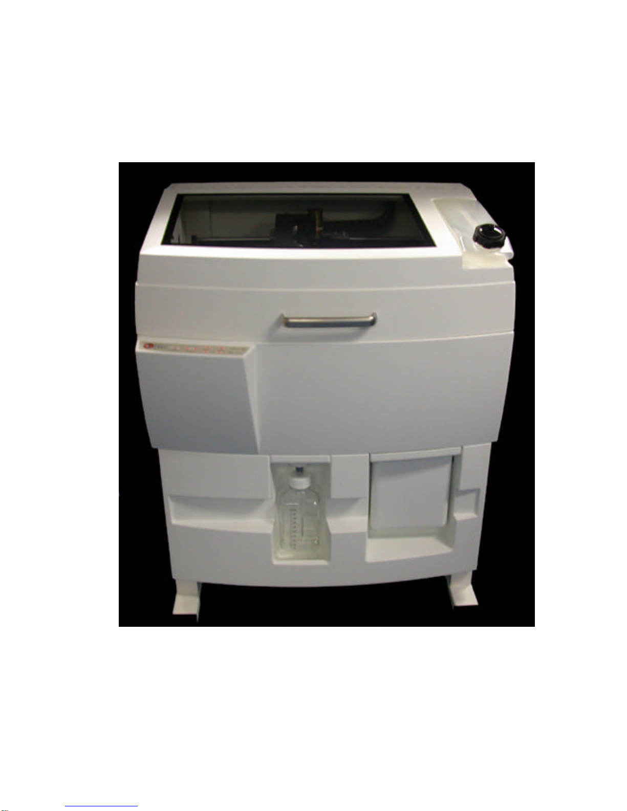
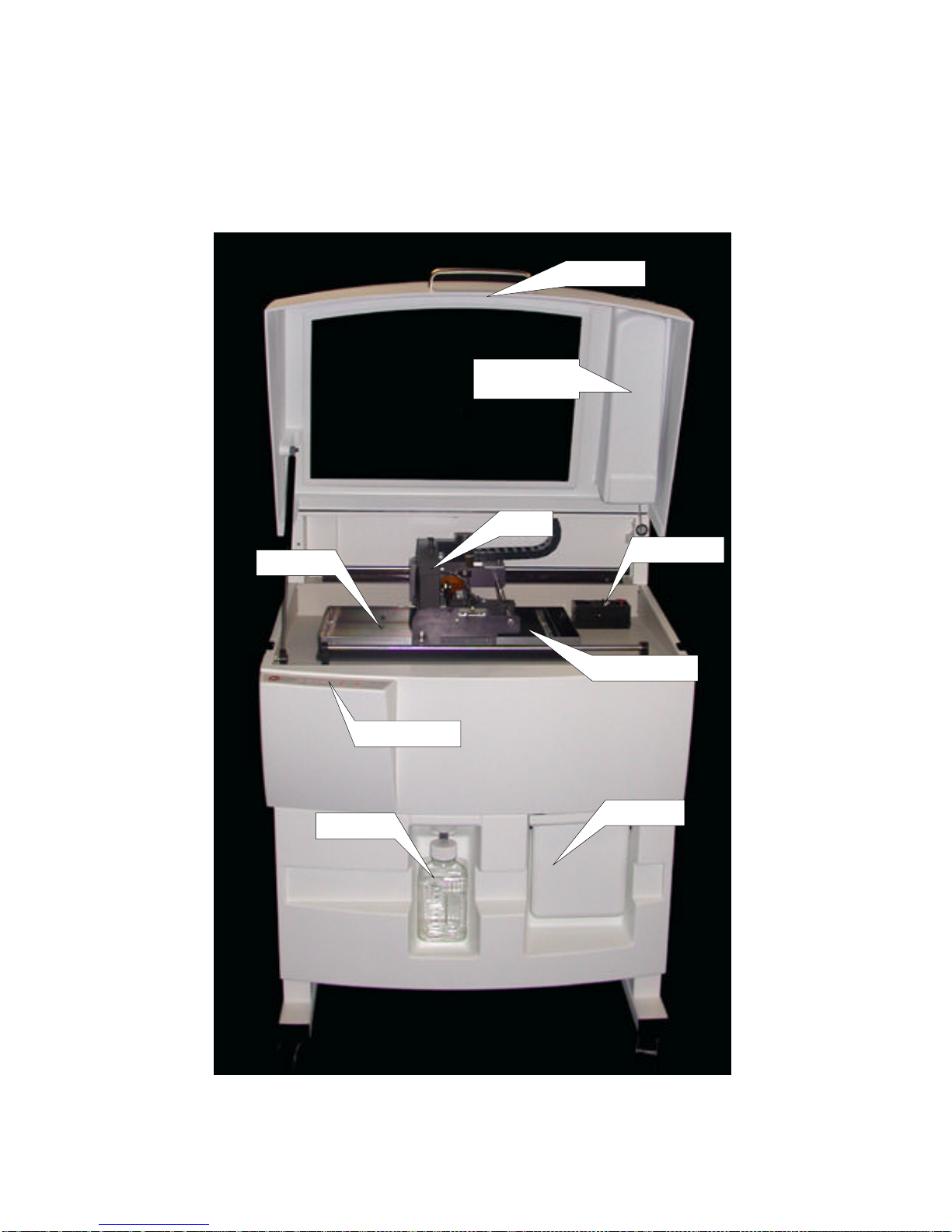
SYSTEM COMPONENTS ........................................................................................................................... 9
ZPRINTER 310 SUBCOMPONENTS........................................................................................................... 10
CHAPTER 2 - QUICK STARTGUIDE ..................................................................................................................... 14
PRINTER PREPARATION......................................................................................................................... 15
PARTPRINTING .................................................................................................................................. 17
POST PROCESSING.............................................................................................................................. 19
USEFUL TIPS ..................................................................................................................................... 20
PARTSETUP AND POST-PROCESSING ......................................................................................... 20
OVEN DRYTHE PART.............................................................................................................. 21
PARTINFILTRATION .................................................................................................................. 21
CHAPTER 3 - MATERIAL SYSTEMS ...................................................................................................................... 22
USING ZCASTTM POWDER .................................................................................................................... 23
GENERAL INFORMATION ............................................................................................................ 23
USING ZCAST ONYOUR ZPRINTER 310 PRINTER ........................................................................ 23
LOADING ZCAST POWDER ........................................................................................................ 28
SETTING UPZCAST BUILDS ..................................................................................................... 28
POST PROCESSING ................................................................................................................. 28
MATERIAL ORDERING............................................................................................................... 29
RECYCLING ........................................................................................................................... 29
STORAGE.............................................................................................................................. 29
DISPOSAL ............................................................................................................................. 29
USING ZP®250 POWDER ...................................................................................................................... 30
MACHINE SETUP .................................................................................................................... 30
SOFTWARE SETUP .................................................................................................................. 30
PARTREMOVAL AND POST PROCESSING...................................................................................... 32
INFILTRATION ADDENDUM .......................................................................................................... 33
CHAPTER 4 - PREPARING THE 3D PRINTER .......................................................................................................... 34
TURNING THE PRINTER ON................................................................................................................... 35
PREPARING THE BUILD ......................................................................................................................... 36
FILLING THE FEED BOX............................................................................................................ 36
REMOVING AIR FROM POWDER AND PACKING THE FEED BOX ........................................................... 37
PREPARING THE BUILD AREA..................................................................................................... 38
CLEANING UP.................................................................................................................................... 39
CLEANING THE SERVICE STATION ............................................................................................................ 40
CLEANING THE SQUEEGEES AND PARKING CAPS ........................................................................... 40
REFILLING THE BINDER BOTTLE .............................................................................................................. 43
CHANGING THE PRINT HEAD .................................................................................................................. 43
EMPTYING THE WASTE BOTTLE .............................................................................................................. 44
PUTTING THE PRINTER ONLINE............................................................................................................... 44
CHAPTER 5 - USING ZPRINT SOFTWARE .............................................................................................................. 45
OPENING OR IMPORTING AFILE .............................................................................................................. 46
ORIENTING THE PART........................................................................................................................... 46
PARTCONTAINING AN OPENING OR HOLLOW AREA ........................................................................ 46
PARTCONTAINING OVERHANGS ................................................................................................. 47

CHECKING BUILD SETTINGS................................................................................................................... 48
SETTING POWDER PARAMETERS ............................................................................................................ 49
ANISOTROPIC SCALING VALUES ................................................................................................. 49
SATURATION VALUES ............................................................................................................... 50
PRINTING THE BUILD ............................................................................................................................ 50
CHAPTER 6 - POST-PROCESSING ........................................................................................................................ 51
REMOVING THE PRINTED PART............................................................................................................... 52
DEPOWDERING THE PART..................................................................................................................... 53
DRYING THE PART............................................................................................................................... 53
INFILTRATING THE PARTWITH Z-KOTE RESINS ........................................................................................... 54
USING Z-MAXTM EPOXY ........................................................................................................... 54
USING ZBONDTM 100 CYANOACRYLATE....................................................................................... 56
USING Z-SNAPTM EPOXY ......................................................................................................... 57
USING PARAPLAST X-TRA WAX ............................................................................................... 58
CHAPTER 7 - APPLICATIONS .............................................................................................................................. 59
GLUING MULTI-PIECE PARTS ................................................................................................................... 61
PAINTING PARTS ................................................................................................................................. 62
POLYESTER RESIN .............................................................................................................................. 63
ELECTROPLATING ................................................................................................................................ 64
WATER TRANSFER PRINTING ................................................................................................................. 65
INVESTMENT CASTING .......................................................................................................................... 68
FLEXIBLE PARTS ................................................................................................................................. 70
THERMOFORMING ................................................................................................................................ 71
RTV MOLDING ................................................................................................................................... 73
CHAPTER 8 - MAINTENANCE .............................................................................................................................. 77
CHANGING PRINT HEADS ...................................................................................................................... 78
CLEANING POGO PINS ......................................................................................................................... 80
OILING THE FAST AXIS ........................................................................................................................ 81
REFILLING THE WASH FLUID RESERVOIR .................................................................................................. 84
GREASING THE SLOW AXIS.................................................................................................................... 86
GREASING THE PISTON SCREWS ............................................................................................................ 87
CHANGING BINDER TANK ...................................................................................................................... 88
CHANGING BINDER COLOR .................................................................................................................... 89
BLEEDING AIR FROM THE FLUID LINES ..................................................................................................... 90
MACHINE STATUS ................................................................................................................................ 91
CHAPTER 9 - SYSTEM DETAILS .......................................................................................................................... 92
INDEX ........................................................................................................................................................... 95

THIS CHAPTER WILL GIVE YOU AN OVERVIEW
OF THE PRINCIPLES BEHIND THE ZPRINTER 310
SYSTEM, FAMILIARIZE YOU WITH THE TERMI-
NOLOGY WE WILL USE TODESCRIBE THE SYS-
TEM, AND INTRODUCE YOU TOSOME OF THE
FEATURES OF THIS MANUAL.
FOR ADDITIONAL INFORMATION, PLEASE
CONTACT THE Z CORPORATION SERVICE
DEPARTMENT AT(781) 852-5050,TOLL-FREE
AT(877) 88-ZCORP OR VIA EMAIL AT
SERVICE@ZCORP.COM. YOU MAYALSO VISIT
THE USER GROUP WEBSITE ATWWW.ZCORP-
USERS.COM.
OVERVIEW
CHAPTER 1

5www.zcorp-users.com
MANUAL OVERVIEW
This ZPrinterTM 310 User Manual will speed you along the path towards quickly and inexpensively building parts.
We recommend that you use this manual together with service training for best results. The manual contains the
following sections:
1. Introduction.This section provides anoverviewoftheprinciplesbehind the ZPrinter 310System, familiarizes
you with the terminology we will use to describe the System, and reviews the components of the System.
2. Quick Start Guide.This section provides an overview of the steps needed to print a part.
3. Material Systems. This sectioninstructs you onhow to useZCastTM Powderandzp®250powderwithinstructions
on how to prepare your printer, print and post-process the part.
4. Preparing the ZPrinter 310 to Print. This section guides you through putting powder and binder solution in
the Printer, and cleaning the Service Station.
5. Printing a Part. This section takes you through preparing the build and checking parameters in the ZPrint
Software before printing.
6. Post Processing. Thissection leads youthrough removing theprinted parts fromthe buildenvelope,removing
excess powder from the part, and infiltrating the parts to improve strength and surface finish.
7. Applications. In this section you will learn some advanced post-processing steps that will enable you to
enhance the way you use the 3D Printer.
8. Maintenance. Here we review a few preventative maintenance steps, offer some tips for troubleshooting and
inform you about where to go if you experience any problems with the system.

HOW IT WORKS
Z Corporation 3D Printer processes are based on the Massachusetts Institute of Technology’s patented 3DPTM
(Three-Dimensional Printing) technology.
The Our proprietary ZPrint Software first converts a three-dimensional design built using 3D CAD into cross-
sections or slices that can be between 0.003" – 009" (0.0762 - 0.2286 mm) thick.
The ZPrinter 310 then prints these cross-sections one after another from the bottom of the design to the top.
Inside the printer there are two pistons. The feed piston is represented in the diagrams below on the left and is
shown in the ‘down’ position filled with powder. The build piston is the piston on the right, shown below in the ‘up’
position. Also represented in the diagrams is the roller (drawn as a circle) and the print assembly (drawn as a
square.) On the printer, the roller and the print assembly are mounted together on the gantry which moves
horizontally across the build area.
Tobegin the 3D printingprocess,the ZPrinter 310 firstspreadsa layer of zp®seriespowder in the samethickness
as the cross section to be printed. The HP print head then applies a binder solution to the powder, causing the
powder particles to bind to one another and to the printed cross-section one level below. The feed piston comes
up and the build piston drops one layer of the thickness. The printer then spreads a new layer of powder and
repeats the process, and in a short time the entire part is printed.

7www.zcorp-users.com
The ZPrinter 310 employs several techniques to quickly build great parts. First, binder solution is applied in a
higherconcentrationaround the edges of the part, creating astrong “shell” around the exterior of the part. Within
parts,theprinter builds an infrastructure by printingstrongscaffolding within part walls with ahigherconcentration
ofbinder solution. The remaining interior areasare printed with alowersaturation, which gives themstability,but
prevents over saturation, which can lead to part distortion.
After printing, the part is removed from the powder bed, depowdered and dried. The part can then be infiltrated
with wax, or other performance resins to increase strength and durability. For more information regarding
infiltrants, see Chapter 6,Post-Processing.
Because the powder layers support the structures being printed above, the ZPrinter 310 prints parts without
support structures of any kind and can print parts with complex geometries that are impossible for other systems.
There are several important characteristics of the ZPrinter 310 that will help you print the best parts for your
intended purpose.
Part Placement. ZPrint Software will place the parts within the build box to maximize build speed, the most
important criteria for the majority of our users. ZPrint Software positions the parts with the smallest dimension
in the z (vertical) axis. In addition to part placement, however, the following other characteristics should be
considered.
Strength. Theultimatestrengthof the part will be affected by its orientation within the printbox. Thepart will be
strongest along the y-axis and the x-axis and less strong along the z-axis. This is because the cross sections are
printed in continuous strips along the y-axis (the binder cartridge direction of travel), bands across the x-axis (the
gantry direction of travel) and laminated layers along the z-axis. This discussion only applies to untreated parts;
once parts are infiltrated, they uniformly take on the strength characteristics of the infiltrating material.

z
-axis
x
-axis
y
-axis
Strong
L
ess Strong
Accuracy. The accuracy of the system depends on the materials you choose. You can employ the anisotropic
scaling feature in the ZPrint Software to adjust for expected shrinkage and bring your parts into true scale. More
information on anisotropic scaling factors is found in Chapter 4,Preparing the 3D Printer.
Strong

9www.zcorp-users.com
SYSTEM COMPONENTS
ZD4i Depowdering Station
ZPrinter 310 System

ZPRINTER 310 SUBCOMPONENTS
ZPrinter 310 System
Top Cover
Gantry
Feed Piston
Build Piston
Control Panel
Service Station
Waste Bottle Overflow Bin
Binder Bottle (on
the Top Cover)

11www.zcorp-users.com
Power Switch
(on side)
Fan
Power Entry
Voltage Switch
Mouse Connector
(not used)
Ethernet
Connection
Bottom View of
Electronics Box
Keyboard Connector
Serial Connector
Video Connector
Back Panel View

Gantry (Top View)
Squeegee
Scraper
Oil Filler
Holes Carriage
Assembly
Carriage
Latch
Carriage
Plunger
Fast Axis Rails
Front
Snowplow
Cable Cover
Rear
Snowplow

13www.zcorp-users.com
Control Panel
Service Station (Top View)
Squeegees
Parking Cap
Wash Fluid
Reservoir
Wick
Online/Offline.
Enables and
disables printer
communication.
Spread. This button allows you to
move the gantry from left to right
and allows you to spread powder
over the build box. Holding down
this button will result in continuous
spreading of powder.
Feed Up/Feed Down. Allows
the user to raise or lower the
piston in the feed box. A light
tap raises or lowers a small
distance; holding down causes
continuous motion.
Build Up/Build Down.
Allows the user to raise or
lower the build box. A light
tap raises or lowers a small
distance; holding down
causes continuous motion.

THIS CHAPTER PROVIDES AN OVERVIEW OF THE
SET-UP, PARTREMOVAL, AND PARTPOST-
PROCESSING STEPS REQUIRED TOPRINT APART.
FOR ADETAILED STEP-BY-STEP GUIDE TO
PRINTER SET-UP, PLEASE REFER TOCHAPTER
4; USING ZPRINT SOFTWARE IN CHAPTER 5;
PARTREMOVAL AND POST PROCESSING IS
COVERED IN CHAPTER 6.
FOR ADDITIONAL INFORMATION ON POST-
PROCESSING TECHNIQUES, REVIEW CHAPTER
7, APPLICATIONS OR VISIT THE Z CORP. USER
WEBSITE ATWWW.ZCORP-USERS.COM.
QUICK START
GUIDE
CHAPTER 2

15www.zcorp-users.com
PRINTER PREPARATION
1. Fill the feed box with powder. Remember to use any
powder in the overflow bin. Add fresh powder as needed.
2. Spread powder over build area.
3. Vacuum any remaining powder on the top deck.
4. Clean and wipe the squeegees and parking cap on the
service station with distilled water.
5. Clean the squeegee scraper with a damp paper towel.

6.Check binderleveland fillif necessary. Fillthe binder
fluid to the neck of the tank.
8. Put printer online.
7. Check the waste bottle. Remove and dispose of liq-
uid in accordance with local disposal regulations.

17www.zcorp-users.com
PARTPRINTING
1. Launch the ZPrint Software application. Open or import the file for the build.
2. Check 3D Print Setup. Make sure the software is communicating with the printer by selecting ‘Select Printer’.
Then choose either serial or network depending on how the printer is connected to the computer. The printer
should show up as an option if the software is properly communicating with the printer.
3. Change any powder parameters if necessary.

3. View build in 2D View and examine the cross-sections of the build. It is also recommended that collision
detection be processed, found under the View menu in the ZPrint System Software (if the build contains multiple
parts) before beginning your build.
4. Press 3D Print and begin the build.

19www.zcorp-users.com
POST PROCESSING
1.Remove excesspowderfromthepart andremove itfrom
the build box.
2. Depowder the part in the depowdering station.
3. Strengthen the part with the infiltration of your choice.
See Chapter 6,Post-Processing.

USEFUL TIPS
PARTSETUP AND POST-PROCESSING
PART SETUP, ORIENTATION, AND PRINT SETTINGS
•Do not tightly pack parts into the build. Keep in mind that you will need to depowder and remove them
from the build box. Allow a little room around the part so you can vacuum the powder away and get your
fingers around or under it.
•Orient parts so delicate features are supported in the z-axis, i.e. keep the attaching feature directly
below the fragile features. If a delicate feature is only supported by unprinted powder the chances of
breaking that small feature during depowdering is greatly increased.
•When building delicate parts use the “Fixture” function to cradle the part. Raising the part 0.25" (6.4
mm) from the bottom of the build and creating a fixture under the part will produce a cradle that can be
handled. The part inside the cradle can easily be transported to an oven or the depowderer.
•Do not enable the bleed compensation feature if you are building a part with features under 0.050" (1.27
mm). Enabling bleed compensation may reduce the feature size.
•To increase the strength of thin parts, you can decrease the layer thickness to 0.0035" (0.089 mm) if you
are using one of the zp®100 series (plaster-based) powder systems. Then choose to override the
saturation values. Input the saturation values used for printing at 0.004" (0.102 mm). This increases the
binder to powder ratio and wets more of the resins in the powder system. As you increase the strength
ofthepart in this manner you arealsoinceasing the amount of time to drythe part. Use of the removable
build plate and oven drying the part are recommended.
GROSS AND FINE DEPOWDERING
•Become familiar with where the parts are placed and how they are oriented in the build box so you do
not accidentally bump or brush against a fragile part during the depowdering process.
•When performing the gross depowdering (removal of excess powder in the build box) do not plunge the
vacuum nozzle into the powder bed. Begin at the outer perimeter of the build box, slowly work your way
into the build. Hold the tip of vacuum nozzle approximately 0.25" (6.4 mm) to .375" (9.5 mm) away from
the powder and allow the vacuum to pull the powder up. Slanting the vacuum nozzle will enable you to
control the suction. This will decrease the chance of breaking a part that is hidden beneath the surface
of the powder.
•While fine depowdering in the depowderer, always start with a low air pressure and gradually increase
the pressure as the fine details and features of the part become visible. When the top and sides of the
part are completely depowdered tilt the part onto one of its sides. Handle the part carefully. The part
may be fragile and brittle before infiltration. If none of the sides of the part will be able to support the
weightofthe part you can apply asmallamount of resin or epoxy to strengthenit. You want to be careful
not to let any of the infiltrant come into contact with any unprinted powder that may still be on the part.
Let the infiltrant dry before continuing to depowder.
USE OF THE REMOVABLE BUILD PLATE
•The removable build plate is an excellent tool for the new user. It allows you to quickly remove the part
from the build bed and begin printing again. The build plate also allows the user to easily transport the
part to the oven (at temperatures below 150oF or 66oC) or the depowdering station without ever having
to handle the part.
Other manuals for ZPrinter 310
1
Table of contents
Other Zcorporation 3D Printer manuals

Zcorporation
Zcorporation ZPRINTER 310 PLUS User manual

Zcorporation
Zcorporation SPECTRUM Z M510 User manual

Zcorporation
Zcorporation ZPrinter 650 User manual

Zcorporation
Zcorporation Z810 User manual

Zcorporation
Zcorporation Z 406 User manual

Zcorporation
Zcorporation Spectrum Z 510 User manual

Zcorporation
Zcorporation Z 406 User manual

Zcorporation
Zcorporation Z402C User manual

Zcorporation
Zcorporation ZPrinter 650 User manual

Zcorporation
Zcorporation zprinter 450 User manual