2
EN
EN
EN
EN
EN
EN
EN
EN
EN
EN
EN
EN
EN
EN
EN
EN
EN
EN
EN
EN
EN
EN
EN
EN
EN
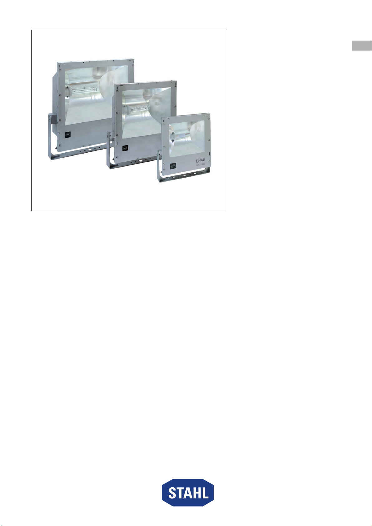
Floodlight
Series 6521/4
Contents
1 General Information ............................................................................................3
1.1 Manufacturer .......................................................................................................3
1.2 Information regarding the Operating Instructions ................................................3
1.3 Further Documents .............................................................................................3
1.4 Conformity with Standards and Regulations .......................................................3
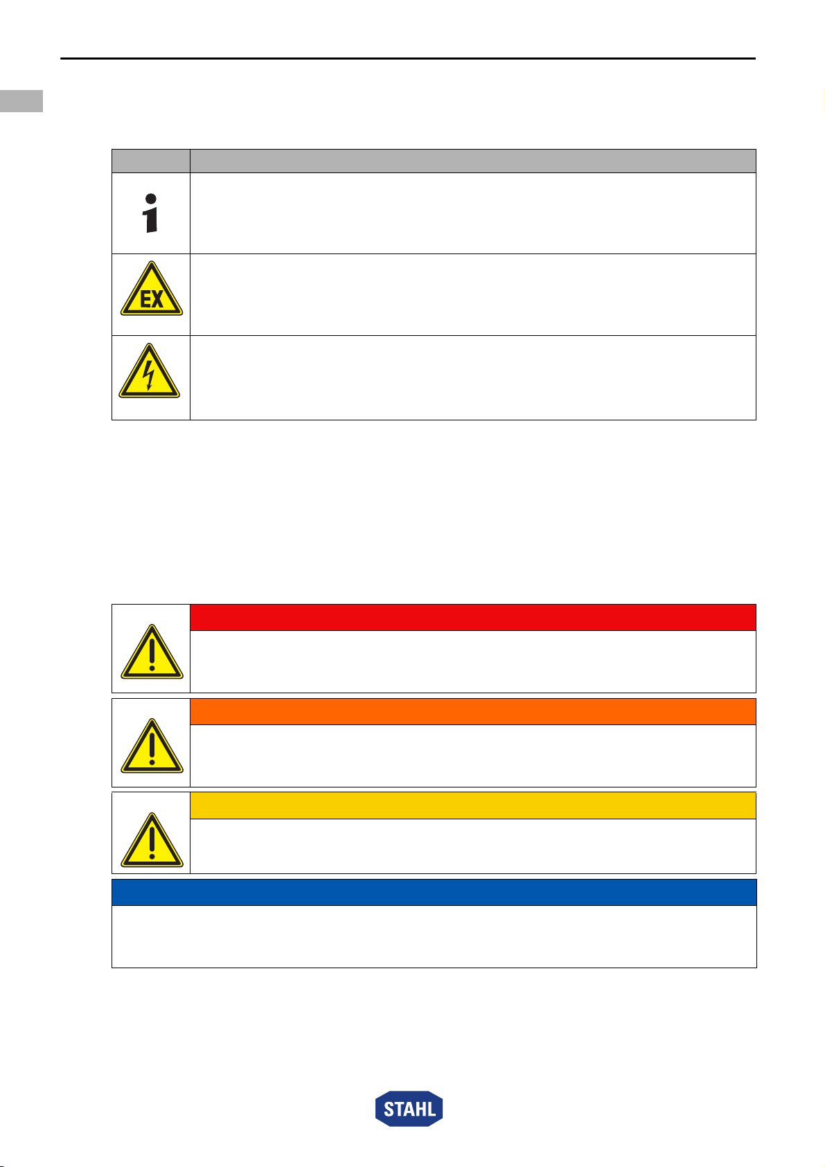
2 Explanation of the Symbols ................................................................................4
2.1 Symbols in these Operating Instructions ............................................................4
2.2 Warning Notes ....................................................................................................4
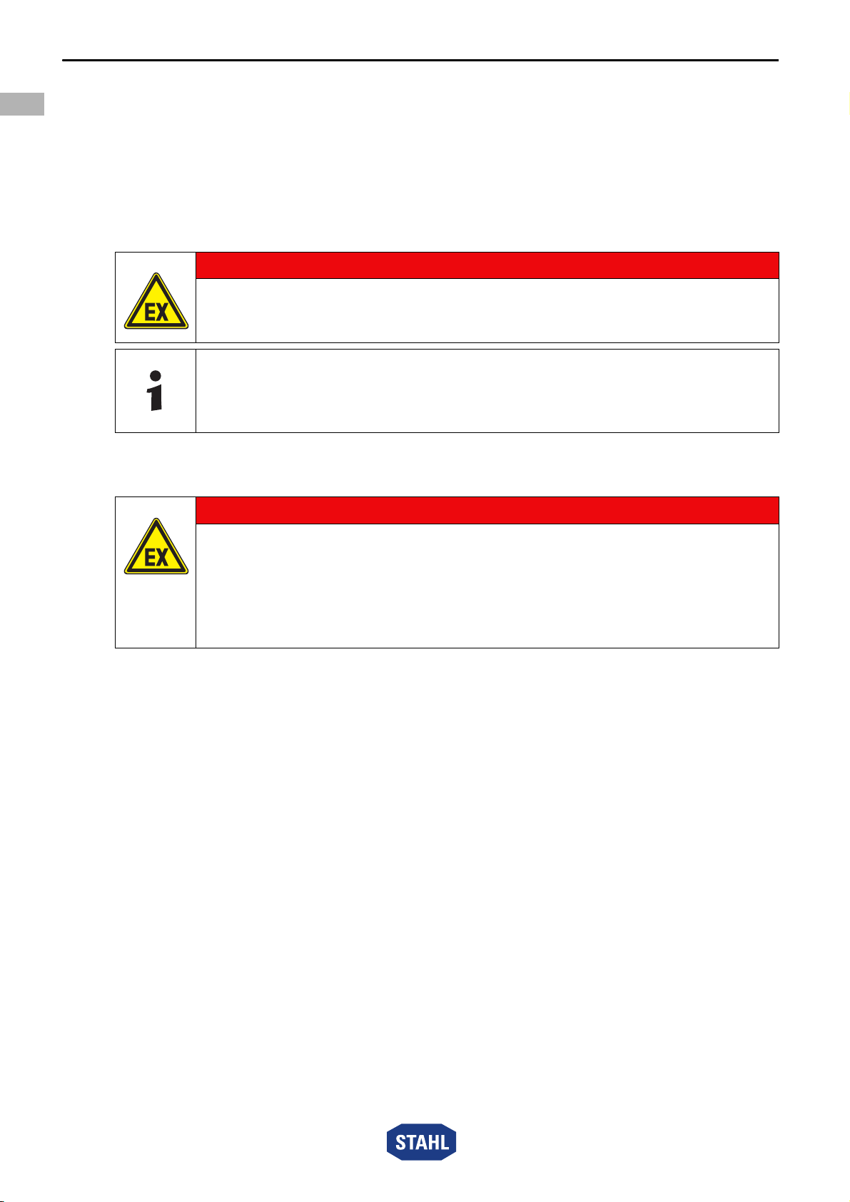
2.3 Symbols on the Device .......................................................................................5
3 Safety Notes .......................................................................................................5
3.1 Operating Instructions Storage ...........................................................................5
3.2 Safe Use .............................................................................................................5
3.3 Intended Use .......................................................................................................6
3.4 Modifications and Alterations ..............................................................................6
4 Function and Device Design ...............................................................................6
4.1 Function ..............................................................................................................6
4.2 Device Design .....................................................................................................7
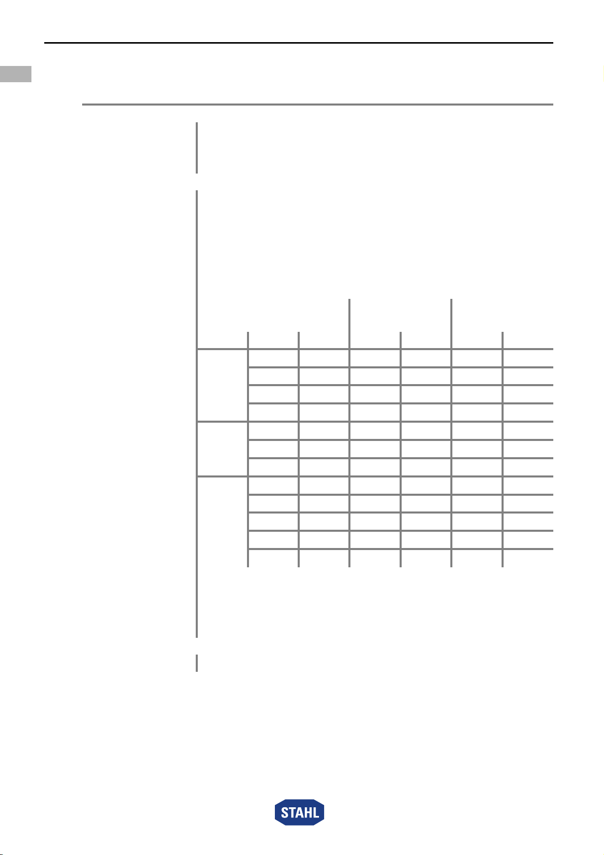
5 Technical Data ....................................................................................................8
6 Transport and Storage ......................................................................................12
7 Mounting and Installation ..................................................................................13
7.1 Dimensions / Fastening Dimensions .................................................................13
7.2 Mounting / Dismounting, Operating Position .....................................................16
7.3 Installation .........................................................................................................16
8 Commissioning .................................................................................................20
9 Operation ..........................................................................................................21
9.1 Troubleshooting ................................................................................................21
10 Maintenance, Overhaul, Repair ........................................................................21
10.1 Maintenance .....................................................................................................22
10.2 Repair ...............................................................................................................24
10.3 Returning the Device ........................................................................................24
11 Cleaning ............................................................................................................25
12 Disposal ............................................................................................................25
13 Accessories and Spare Parts ............................................................................25