Stahl SERIES 400 User manual

Installation Manual
SERIES 600 KVM Systems
SERIES 500 Thin Clients
SERIES 400 Panel PC
Device platform SHARK
ET-xx8 / MT-xx8
HW-Rev. ET-xx8: 01.01.00
HW-Rev. MT-xx8: 01.01.00
Installation Manual version: 01.01.02
Issue date: 11.03.2020

Installation Manual ET-/MT-xx8 Disclaimer
Page 2 of 91 R. STAHL HMI Systems GmbH / IM_ET_MT-xx8_en_V_01_01_02.docx / 11.03.2020
Disclaimer
Publisher and copyright holder:
R. STAHL HMI Systems GmbH
Adolf-Grimme-Allee 8
D 50829 Köln
Telephone: (Sales Support) +49 (0) 221 76 806 - 1000
(Technical Support) - 5000
Fax: - 4100
All rights reserved.
This document may not be reproduced in whole or in part except with the written consent
of the publisher.
This document may be subject to change without notice (data, dimensions, weights,
constructions, drawings, pictures etc.).
Any warranty claims are limited to the right to demand amendments. Liability for any damage that
might result from the content of this description or all other documentation is limited to clear cases
of premeditation.
We reserve the right to change our products and their specifications at any time, provided it is in
the interest of technical progress. The information in the current manual (online or on CD / DVD /
USB stick) or in the operating instructions included in the delivery applies.
Trademarks
The terms and names used in this document are registered trademarks and / or products of the
companies in question.
Copyright © 2020 R. STAHL HMI Systems GmbH. Subject to alterations.

Installation Manual ET-/MT-xx8 Table of contents
R. STAHL HMI Systems GmbH / IM_ET_MT-xx8_en_V_01_01_02.docx / 11.03.2020 Page 3 of 91
Table of contents
Description Page
Disclaimer 2
Table of contents 3
1Application and location 6
2General notes 6
3Warnings 6
3.1 Touch operation 6
4Mounting 7
4.1 Mounting / Installation 7
4.2 Recommended mountings 8
4.3 Mounting notes 9
5Variation of operating temperature range 10
6Design 12
6.1 Rear view VESA 200 standard 12
6.1.1 View to connection compartment and side 12
6.2 Rear view VESA 200 Top Connect 13
6.2.1 View to connection compartment and side 13
7Tools 14
8Mechanical installation 14
8.1 Accessories 14
8.2 Device dimensions 15
8.2.1 Front 15
8.2.2 Side 15
8.3 Cable glands 16
8.3.1 VESA 200 Standard 16
8.3.2 VESA 200 Top Connect 16
8.4 VESA 200 standard mounting option 17
8.5 VESA 200 Top Connect mounting option 17
8.6 Mounting with handle and feet 18
8.7 Wall mounting 19
8.7.1 View 19
8.7.2 Dimensions 19
8.7.3 Wall mounting bracket 19
8.7.4 Hole size wall mounting bracket 20
8.7.5 Mounting –step by step 20
8.8 Wall mounting with keyboard 22
8.8.1 View 22
8.8.2 Dimensions 22
8.8.3 Keyboard 23
8.8.4 Wall mounting bracket 23
8.8.5 Mounting –step by step 24
8.9 Wall mounting with barcode reader 26
8.9.1 View 26
8.9.2 Dimensions 26
8.9.3 Brackets 28

Installation Manual ET-/MT-xx8 Table of contents
Page 4 of 91 R. STAHL HMI Systems GmbH / IM_ET_MT-xx8_en_V_01_01_02.docx / 11.03.2020
8.9.3.1 Scanner bracket 28
8.9.3.2 Adaptor for Scanner bracket 28
8.9.4 Mounting –step by step 28
8.10 Mounting on Stand 33
8.10.1 View 33
8.10.2 Dimensions 33
8.10.3 Stand MPFL 34
8.10.4 Yoke 34
8.10.5 Coupling cover 34
8.10.6 Mounting –step by step 35
8.11 Mounting on stand with keyboard 40
8.11.1 View 40
8.11.2 Dimensions 40
8.11.3 Keyboard 41
8.11.4 Mounting –step by step 41
8.12 Mounting on Stand with barcode reader 43
8.12.1 View 43
8.12.2 Dimensions 43
8.12.2.1 Scanner bracket 44
8.12.3 Mounting –step by step 45
8.13 Mounting on elbow 48
8.13.1 View 48
8.13.2 Dimensions 48
8.13.3 Elbow MPW 48
8.13.4 Yoke 49
8.13.5 Coupling cover 49
8.13.6 Mounting –step by step 49
8.14 Mounting on elbow with keyboard 52
8.14.1 View 52
8.14.2 Dimensions 52
8.14.3 Keyboard 53
8.14.4 Mounting –step by step 53
8.15 Mounting on elbow with barcode reader 54
8.15.1 View 54
8.15.2 Dimensions 54
8.15.3 Scanner bracket 55
8.15.4 Mounting –step by step 55
8.16 Mounting sun roof 57
8.16.1 View 57
8.16.2 Dimensions 57
8.16.3 Sun roof 58
8.16.4 Mounting –step by step 58
8.16.5 Sun roof locking 59
8.16.6 Changing sun roof inclination 60
8.16.7 Sun roof mounting options 63
8.17 Mounting push button 65
8.17.1 View 65

Installation Manual ET-/MT-xx8 Table of contents
R. STAHL HMI Systems GmbH / IM_ET_MT-xx8_en_V_01_01_02.docx / 11.03.2020 Page 5 of 91
8.17.2 Components of push button 66
8.17.3 Mounting –step by step 66
9Elektrical installation 72
9.1 Status LED 72
9.2 Connection overview terminal assignment 72
9.3 Terminal view VESA 200 standard 75
9.3.1 SERIES 600 75
9.3.1.1 Variant TX (copper) 75
9.3.1.2 Variant SX or LX (fibre optics) 75
9.3.2 SERIES 400 / 500 76
9.3.2.1 Variant TX (copper) 76
9.3.2.2 Variant FX (fibre optics) 76
9.4 Terminal view VESA 200 Top Connect 76
9.5 Connection overview to KVM Box 77
9.5.1 Variant TX (copper) 77
9.5.2 Variant SX or LX (fibre optics) 77
9.6 Elektrical connection VESA 200 standard - step by step 78
9.6.1 Earthing 78
9.6.2 Supply and data lines 80
9.7 Elektrical connection VESA 200 Top Connect - step by step 85
9.7.1 Earthing 85
9.7.2 Supply and data lines 87
9.8 Accessories 88
9.8.1 Keyboard KBDi-USB 88
9.8.1.1 View VESA 200 standard 88
9.8.1.2 View VESA 200 Top Connect 88
9.8.1.3 Connection and wiring keyboard 89
10 Release notes 90

Installation Manual ET-/MT-xx8 Application and location
Page 6 of 91 R. STAHL HMI Systems GmbH / IM_ET_MT-xx8_en_V_01_01_02.docx / 11.03.2020
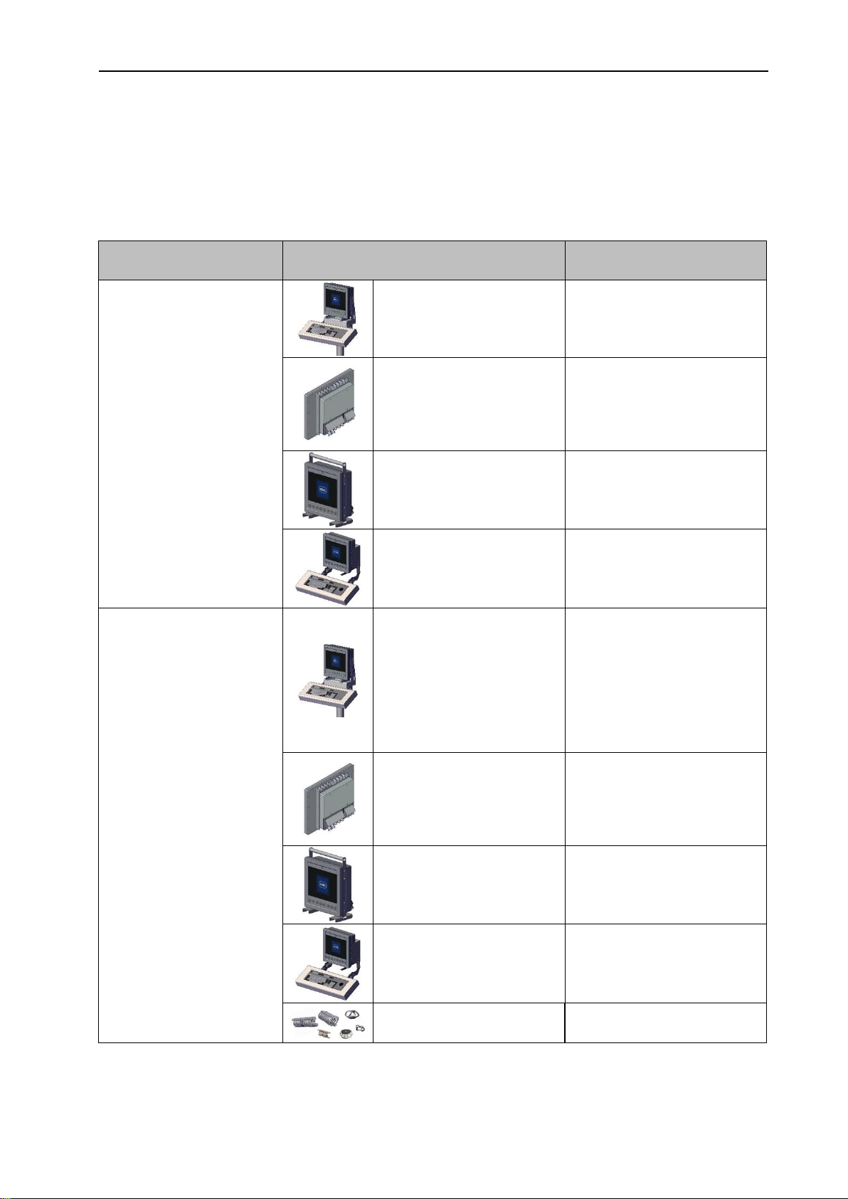
1 Application and location
The ET-/MT-xx8 devices, device platform SHARK (SERIES 400 / 500 and 600) are specially
designed for the Oil and Gas Industry. They can be mounted at Rig floors (fixed or mobile), drillers
/ crane cabins as well as wireline mounting and tankfarms. Suiteable for usage in hazardous
areas zone 1, 21, 2 and 22 (depending of device type), this devices are ideally for a large numbers
of applications.
2 General notes
If not otherwise specified, all information, descriptions and
illustrations apply in the same way to devices x38 and x98 as well as
versions "Standard" and "Top Connect", even if the illustrations only
show one version !
3 Warnings
3.1 Touch operation
Incorrect / phantom operation:
Incorrect operation of the touch screen may result in accidental functions and errors. The
operating device will then be unable to implement these, may implement these incorrectly or in a
way not intended!
- Do not realise safety-relevant functions via the touch screen !
- Avoid accidental multi-touches !
- Do not touch the touch screen across a large area !
- Use a touch pen only for the capacitive touch screen !
- Before operating the device, thoroughly acquaint yourself with the multi-touch functions of
the operating system and the application !
- Switch off the device for cleaning and maintenance !
Conductive liquids on the touch screen can result in incorrect or phantom operations. This applies
in particular to salt water.
- Avoid contamination of the touch screen surface with salt water.
Protect the device bevor rain, snow and splash water, because large quantity of stand or floating
water can disturb the operation and can cause in unwanted cursor movements.
This protection can be done with a sun roof or any other covered construction. Strong wind, salt
water and rain had to be considered in this thoughts offshore.
Damage of the touch screen:
Only touch the touch screen with your fingers or a appropriate touch pen.
- Avoid contacts with pointed or sharp objects, this can damage the touch screen and lead
to a significant reduction in service life or even total failure of the touch screen !
NOTICE

Installation Manual ET-/MT-xx8 Mounting
R. STAHL HMI Systems GmbH / IM_ET_MT-xx8_en_V_01_01_02.docx / 11.03.2020 Page 7 of 91
4 Mounting
Basically all devices from the platform SHARK are designed to withstand vibrations and shocks.
In regards of different applications and ambient conditions we recommend following installations:
For all installations in locations with higher shocks and vibration consider to use “Cable Mounts”
for absorbing shock and vibration.
4.1 Mounting / Installation
Mounting on stand / pedestal,
with / without external keyboard
Wall mounting,
with / without external keyboard
VESA 200 mounting option
Mounting with handle and feet
Mounting mit cable mounts

Installation Manual ET-/MT-xx8 Mounting
Page 8 of 91 R. STAHL HMI Systems GmbH / IM_ET_MT-xx8_en_V_01_01_02.docx / 11.03.2020
4.2 Recommended mountings
This recommendations are the result of mounting solutions over many years.
Please follow this mounting recommendation to mount the HMI in a best way.
Especially in Oil & Gas applications it is very important to check the vibration and shock conditions
before mount the HMI. As we do not know the detailed condition of your application we can not
take any responsibility for the mounting.
Condition at mounting
area
Mounting / Installation
Recommendation
No vibrations and / or no
shocks
Mounting on stand /
pedestal, with / without
external keyboard
No restriction
VESA 200 mounting
option
No restriction
Mounting with handle
and feet
No restriction
Wall mounting,
with / without external
keyboard
No restriction
Vibration (sinus)
5 … 13.2 Hz: ±1 mm
13.2 … 100 Hz: ±0.7 g
Swipe cycle 1 oct/min
Axis X, Y, Z
according to
IEC 60068-2-6 and
DNV / GL certificate
Nr. 2.4 (2006)
Mounting on stand /
pedestal, with / without
external keyboard
Installation needs secure
fixation on the ground.
Stand pipe should be fixed
to the wall close to the
coupling.
Mounting is critical for
higher values of
acceleration forces.
VESA 200 mounting
option
Not recommended
Mounting with handle
and feet
Not recommended
Wall mounting,
with / without external
keyboard
Recommended installation
(DNV / GL tested)
Mounting mit cable
mounts
Recommended installation

Installation Manual ET-/MT-xx8 Mounting
R. STAHL HMI Systems GmbH / IM_ET_MT-xx8_en_V_01_01_02.docx / 11.03.2020 Page 9 of 91
Condition at mounting
area
Mounting / Installation
Recommendation
Shocks
18 impacts 25 g / 6 ms,
Axis X, Y, Z
according to
IEC 60068-2-27
Mounting on stand /
pedestal, with / without
external keyboard
Installation needs secure
fixation on the ground.
Stand pipe should be fixed
to the wall close to the
coupling.
Mounting is critical for
higher values of
acceleration forces.
VESA 200 mounting
option
Not recommended
Mounting with handle
and feet
Not recommended
Wall mounting,
with / without external
keyboard
Recommended installation
Mounting mit cable
mounts
Recommended installation
Vibrations
5…1000 Hz
5 g
Wall mounting,
with / without external
keyboard
Using of “cable mounts” as
vibration and shock
absorbers.
Other installations
Not recommended
4.3 Mounting notes
The tightening torques of the cable glands depends from the used cable and wires.
Therefor the user have to define the tightening torques by himself.
The recommended torque for the M8 screws of the VESA bracket is 25 N to 30 N.
The recommended torque for the M6 screws of the lateral mounting holder is 10 N to
12 N.
The required torque for the Torx screws for mounting the E-Box to the Display-Module
is 10 N.
The recommended torque for the screws of the cover from the connection compartment
is 1 N to 1.5 N.
Before mounting the sun roof, the handle had to be dismounted.

Installation Manual ET-/MT-xx8 Variation of operating temperature range
Page 10 of 91 R. STAHL HMI Systems GmbH / IM_ET_MT-xx8_en_V_01_01_02.docx / 11.03.2020
5 Variation of operating temperature range
The devices' operating temperature range is impacted by how they are mounted, and the
minimum and maximum permitted operating temperature may vary depending on their mounting
type.
These values are listed in the table below.
Exposure to direct sunlight might contribute to a further heating up
of the device and may result in a further reduction of the maximum
permitted operating temperature !
We recommend you protect the device from direct sunlight !
Wind may cool down the device and thus have an impact on the
minimum operating temperature.
The storage temperature is not impacted by the type of installation.
As a rule:
LTC = Lower ambient temperature in °C
-40 °C for devices with integrated heater
-10 °C for devices without heater
LTF = Lower ambient temperature in °F
-40 °F for devices with integrated heater
+14 °F for devices without heater
HTC = Highest permissible ambient temperature in °C
HTF = Highest permissible ambient temperature in °F
Display orientation
Inclination
Description
Highest permissible
ambient temperature
Landscape,
horizontal 90°,
standing free
HTC = +65 °C
HTF = +149 °F
Landscape,
horizontal 45°,
standing free
HTC = +60 °C
HTF = +140 °F
Landscape,
horizontal 0°,
standing free,
minimum gap
10 cm below
device
HTC = 60 °C
HTF = +140 °F
ATTENTION
NOTICE

Installation Manual ET-/MT-xx8 Variation of operating temperature range
R. STAHL HMI Systems GmbH / IM_ET_MT-xx8_en_V_01_01_02.docx / 11.03.2020 Page 11 of 91
Display orientation
Inclination
Description
Highest permissible
ambient temperature
Portrait,
vertical 90°,
standing free
HTC = +60 °C
HTF = +140 °F
Portrait,
vertical 45°,
standing free
HTC = +60 °C
HTF = +140 °F
Landscape,
horizontal,
installation in
enclosure,
inclination
independend
HTC = +50 °C
HTF = +122 °F
Portrait,
horizontal,
installation in
enclosure,
inclination
independend
HTC = +50 °C
HTF = +122 °F

Installation Manual ET-/MT-xx8 Design
Page 12 of 91 R. STAHL HMI Systems GmbH / IM_ET_MT-xx8_en_V_01_01_02.docx / 11.03.2020
6 Design
ET-/MT-x38 (15") ET-/MT-x98 (21.5")
6.1 Rear view VESA 200 standard
6.1.1 View to connection compartment and side
Ex e
compartment
Ex i
compartment

Installation Manual ET-/MT-xx8 Design
R. STAHL HMI Systems GmbH / IM_ET_MT-xx8_en_V_01_01_02.docx / 11.03.2020 Page 13 of 91
6.2 Rear view VESA 200 Top Connect
6.2.1 View to connection compartment and side
Ex e
compartment
Ex i
compartment

Installation Manual ET-/MT-xx8 Tools
Page 14 of 91 R. STAHL HMI Systems GmbH / IM_ET_MT-xx8_en_V_01_01_02.docx / 11.03.2020
7 Tools
1x Side cutter
1x Cable stripper
1x Wrench size SW 10
1x Wrench size SW 13
1x Wrench size SW 14
1x Wrench size SW 17
1x Wrench size SW 24
1x Philips screw driver size 1
1x Philips screw driver size 2
1x Slotted screw driver size 2.5 mm
1x Slotted screw driver size 4.5 mm
1x Torx screw driver size TX 30
1x Hex-wrench size 5
1x Step drill bit approx. 16 –32 mm
1y Drill
8 Mechanical installation
Mount the devices all the time with 2 persons together !
If not otherwise specified, devices x38 and x98 as well as versions
"Standard" and "Top Connect" are mounted in the same way.
8.1 Accessories
The installation instructions for further accessories not
described in this manual are located in the following
documents.
Connection set
Variant
Description
Document
CON-xx8-CAT-ROTA-
AC-ROTA-00
for CAT-variant with AC
power supply
IM_Top-Connect_xx8-*.pdf
CON-xx8-FO-HMA-
AC-ROTA-00
for FO-variant with AC
power supply
IM_Top-Connect_xx8-*.pdf
Power / reset switch
CON-xx8-PSW-ext
On-Off-switch
IFI-PB-an-xx8-Sidemounting-de-
en_V_01.pdf
CAUTION
DOCUMENTATION
NOTICE

Installation Manual ET-/MT-xx8 Mechanical installation
R. STAHL HMI Systems GmbH / IM_ET_MT-xx8_en_V_01_01_02.docx / 11.03.2020 Page 15 of 91
8.2 Device dimensions
8.2.1 Front
Dimensions [mm]
Device
A
B
ET-x38 / MT-x38
380
394
ET-x98 / MT-x98
553
458
8.2.2 Side
Standard Top Connect
Dimensions [mm]
Dimensions [mm]
Device Standard
C
D
E
Device Top Connect
C
D
E
F
G
ET-x38 / MT-x38
137
40
52
ET-x38 / MT-x38
212
40
46
90
257
ET-x98 / MT-x98
141
44
52
ET-x98 / MT-x98
216
44
64
90
304

Installation Manual ET-/MT-xx8 Mechanical installation
Page 16 of 91 R. STAHL HMI Systems GmbH / IM_ET_MT-xx8_en_V_01_01_02.docx / 11.03.2020
8.3 Cable glands
It is allowed to use any other Ex certified cable gland, which
fulfill the technical requirements.
8.3.1 VESA 200 Standard
Standard cable glands type Hummel
Mounting place
Quantity
Size
Cable diameter
[mm]
Hummel
type
Hummel
number
Ex e compartment
2
M25 x 1,5
14 - 18
HSK-MZ-Ex
1641250050
3
M20 x 1,5
10 - 14
HSK-MZ-Ex
1641201650
Ex i compartment
3
M16 x 1,5
4 - 8
HSK-MZ-Ex
1641160050
8.3.2 VESA 200 Top Connect
Screw plugs
Mounting place
Quantity
Size
Ex e compartment
3
M20 x 1,5
Ex i compartment
3
M16 x 1,5
In their factory state, the VESA 200 Top Connect devices come with
screw plugs.
Various sets are available for the connection of cables as
accessories. These must be mounted by the customer.
Connection set
Variant
Description
SAP Nr.
CON-xx8-CAT-ROTA-AC-ROTA-00
for CAT-variant with AC power supply
260583
CON-xx8-FO-HMA-AC-ROTA-00
for FO-variant with AC power supply
260958
NOTICE
NOTICE

Installation Manual ET-/MT-xx8 Mechanical installation
R. STAHL HMI Systems GmbH / IM_ET_MT-xx8_en_V_01_01_02.docx / 11.03.2020 Page 17 of 91
8.4 VESA 200 standard mounting option
Recommended tightening torque M8 screws: 25 N to 30 N
8.5 VESA 200 Top Connect mounting option
Recommended tightening torque M8 screws: 25 N to 30 N
4x M8
200 mm x 200 mm
15 mm
4x
SW 13
4x M8
200 mm x 200 mm
15 mm
4x
SW 13

Installation Manual ET-/MT-xx8 Mechanical installation
Page 18 of 91 R. STAHL HMI Systems GmbH / IM_ET_MT-xx8_en_V_01_01_02.docx / 11.03.2020
8.6 Mounting with handle and feet
Nr
Designation
Quantity
1
Washer 6.4
8
2
Socket head screw M6 x 16
8
5mm

Installation Manual ET-/MT-xx8 Mechanical installation
R. STAHL HMI Systems GmbH / IM_ET_MT-xx8_en_V_01_01_02.docx / 11.03.2020 Page 19 of 91
8.7 Wall mounting
8.7.1 View
ET-/MT-x38 (15")
ET-/MT-x98 (21.5")
8.7.2 Dimensions
Dimensions (mm)
Device
A
B
B Max
C
C Max
ET-x38 / MT-x38 (15")
380
394
428
216
250
ET-x98 / MT-x98 (21,5")
553
458
483
220
250
8.7.3 Wall mounting bracket

Installation Manual ET-/MT-xx8 Mechanical installation
Page 20 of 91 R. STAHL HMI Systems GmbH / IM_ET_MT-xx8_en_V_01_01_02.docx / 11.03.2020
8.7.4 Hole size wall mounting bracket
8.7.5 Mounting –step by step
Nr
Designation
Quantity
1
Socket head
screw M6 x 25
2
2
Washer 6.4
2
4x M10
SW 17
distance to the floor for
ergonomic operation
2
1
First mount the wall mounting bracket on a wall / girder etc.
5 mm
Other manuals for SERIES 400
1
This manual suits for next models
7
Table of contents
Other Stahl Industrial PC manuals
Popular Industrial PC manuals by other brands

Advantech
Advantech ITA-5710 Series Startup manual

DT Research
DT Research 139CS Operation manual

DMP Electronics
DMP Electronics EBOX-3310MX-TS4C user guide

ICP DAS USA
ICP DAS USA VPD-173N quick start guide

ADLINK Technology
ADLINK Technology cPCIS-3100 Series user guide

Arestech
Arestech BPC-3072 user manual