manuals.online logo
Brands
  1. Home
  2. •
  3. Brands
  4. •
  5. Stahl
  6. •
  7. Light Fixture
  8. •
  9. Stahl EXLUX 6008 Series User manual

Stahl EXLUX 6008 Series User manual

Betriebsanleitung
Operating instruction
Mode d‘emploi
ID: 169701/6008611300/R. STAHL/2013-02-05/de-en-fr-06
Explosionsgeschützte
No
t-
lichtleuchten für
Leuchtstofflampen
Explosion protected
emergency light fittings for
fluorescent lamps
Luminaires antidéflagrants de
secours pour tubes fluores-
cents
EXLUX 6008
Ausführung 6008/5
Version 6008/8
Séries 6008/9
Anwendung Application Utilisation
Die Notlichtleuchte der Serie EXLUX 6008
für Leuchtstofflampen ist ein explosions-
geschütztes elektrisches Betriebsmittel
und dient zur Ausleuchtung von Betriebs-
und Lagerstätten in explosionsgefähr-
deten Bereichen der Zonen 1, 2, 21 und
22. Sie sind für den Innen- und Außenbe-
reich einsetzbar.
The emergency light fitting of type EXLUX
6008 for fluorescent lamps is an explosion-
proof electrical appliance and serves to
illuminate places of operation and ware-
houses in areas of zones 1, 2, 21and 22.
They can be used inside or outside.
Le luminaire antidéflagrant de secours
pour tubes fluorescents de la série EXLUX
6008 est un équipement électronique pour
atmosphère explosive. Il est destiné à
éclairage des locaux de production et de
stockage avec environnement dans les
zones 1, 2, 21 et 22. Il peut être utilisé à
l’extérieur comme à l’intérieur.
Zweck dieser Anleitung
Bei Arbeiten in explosionsgefährdeten
Bereichen hängt die Sicherheit von Perso-
nen und Anlagen von der Einhaltung aller
relevanten Sicherheitsvorschriften ab.
Purpose of these instructions
When working in hazardous areas, the
safety of personnel and plant depends on
complying with safety regulations.
Objectif du présent mode d’emploi
Au cours des travaux dans les zones à
risque d’explosion, la sécurité des
hommes et des équipements est liée au
respect de toutes les consignes de sécuri-
té.
Das Montage- und Wartungspersonal,
welches in solchen Anlagen arbeitet, trägt
deshalb eine besondere Verantwortung.
Die Voraussetzung dafür ist die genaue
Kenntnis der geltenden Vorschriften und
Bestimmungen.
Assembly and maintenance staff working
on such plant therefore have a particular
responsibility. They require precise
knowledge of the applicable standards and
regulations.
Le personnel chargé du montage et de la
maintenance sur ces équipements pos-
sède à cet égard une grande responsabili-
té et doit connaître parfaitement les pres-
criptions et dispositions légales en vigueur.
Diese Anleitung fasst kurz die wichtigsten
Sicherheitsmaßnahmen zusammen. Sie
ergänzt die entsprechenden Vorschriften,
zu deren Studium das verantwortliche
Personal verpflichtet ist.
These instructions summarise the most
important safety measures. They supple-
ment the corresponding regulations, which
the staff responsible must study.
Le présent mode d’emploi résume de
façon concise les mesures de sécurité les
plus importantes. Il ne peut en aucun cas
se substituer aux prescriptions correspon-
dantes, dont l’étude par le personnel res-
ponsable demeure obligatoire.
Änderungen vorbehalten. Subject to alterations. Sous réserve de modifications.
R. STAHL Schaltgeräte GmbH
Kompetenzcenter Licht
Nordstraße 10, D-99427 Weimar
Telefon: +49 3643 4324
Telefax: +49 3643 422176
E-Mail: info.leuchten@stahl.de
www.stahl-ex.com
Betriebsanleitung
Operating instruction
Mode d‘emploi
ID: 169701/6008611300/R. STAHL/2013-02-05/de-en-fr-062
Sicherheitshinweise Safety instructions Consignes de sécurité
Beachten Sie bitte folgendes bei Montage und Betrieb der Leuchte:
Observe the following during setting-up and operation of the light fitting:
Lors du montage et du fonctionnement, observer du luminaire:
Verwenden Sie die Leuchte nur für den
zugelassenen Einsatzzweck.
Fehlerhafter oder unzulässiger Einsatz
sowie das Nichtbeachten der Hinweise
dieser Betriebsanleitung schließen eine
Gewährleistung unsererseits aus.
Use the light fitting only for their intended
purpose. Incorrect or impermissible use
invalidates our warranty provision.
N’utilisez le luminaire que dans le but
prévu et autorisé. Toute utilisation incor-
recte ou interdite annule notre garantie.
Umbauten und Veränderungen an der
Leuchte, die den Explosionsschutz beein-
trächtigen, sind nicht gestattet.
Die Leuchte darf nur im unbeschädigten
und sauberen Zustand betrieben werden.
Conversions and modifications on the light
fitting, which would impair explosion pro-
tection are not permitted.
Operate the light fitting only if it is clean
and not damaged.
Il est interdit de procéder à des modifica-
tions le luminaire d'entraver la protection
antidéflagrante.
Utiliser le luminaire un appareil lorsqu'il est
intact et propre.
Bei Errichtung und Betrieb im Anwen-
dungsfall ist Folgendes zu beachten:
When installing and operating and
when in use, the following must be
taken into consideration:
Pour l’installation et l’utilisation/
application spécifique, observer les
points suivants:
•
das Gerätesicherheitsgesetz
•die nationalen Sicherheitsvorschriften
•die nationalen Unfallverhütungvor-
schriften
•die nationalen Montagevorschriften
•die allgemein anerkannten Regeln der
Technik
•die Sicherheitshinweise dieser Be-
triebsanleitung
•die Kennwerte der Typ- und Daten-
schilder
•die Prüfbescheinigungen und die
darin enthaltenen besonderen Bedin-
gungen
•Die Anforderungen der EN 61241-17,
z. B. bezüglich Staubablagerungen
und Temperaturen sind zu beachten!
•
the equipment safety legislation
•the national safety regulations
•the national accident prevention regu-
lations
•the national installation regulations
•the generally recognized technical
regulations
•the safety guidelines in these operat-
ing instructions
•the characteristic values on the rating
and data plates
•the test certificates and the special
conditions outlined in them
•The requirements of EN 61241-17,
e. g. In relation to dust deposits and
temperatures must be observed.
•
la législation sur la sécurité des appa-
reils en vigueur
•les prescriptions de sécurité natio-
nales
•les prescriptions nationales en ma-
tière de prévention des accidents
•les prescriptions nationales de mon-
tage
•les règles généralement re-connues
de la technique
•les consignes de sécurité du présent
mode d’emploi
•les valeurs nominales indiquées sur
les plaques signalétiques
•les certificats d’essais et les condi-
tions particulières auxquels ils se rap-
portent
•Respecter les exigences de la norme
EN 61241-17, par example en matière
d’accumalation de poussière o de
température.
Beschädigungen können den Ex-Schutz
aufheben.
Damage may eliminate the explosion
protection.
Suppression potentielle de la protection
anti-explosion en cas de dommage au
niveau du luminaire.
Eine Kopie der Baumusterprüfbescheinigung senden wir Ihnen auf Anfrage gerne zu. Sie stehen Ihnen auch auf
unserer Homepage – www.stahl-ex.com – unter Explosionsschutz zur Verfügung.
We will forward a copy of the Type Examination/Certificate on request. They are also available on our homepage –
www.stahl-ex.com under Explosionsschutz.
Nous pouvons vous faire parvenir une copie du certificat d’essai de type CEE sur demande. Les certificats d'essai
vous trouvent aussi sur notre homepage sous - www.stahl-ex.com – sous Explosionsschutz.
Betriebsanleitung
Operating instruction
Mode d‘emploi
ID: 169701/6008611300/R. STAHL/2013-02-05/de-en-fr-06 3
1 Normenkonformität 1 Conformity with standards 1 Conformité aux normes
Die relevanten Normen sind in der
Konformitätserklärung aufgelistet.
The relevant standards are listed in the EC
Declaration of Conformity.
Vous trouvez la liste des normes impor-
tantes dans la Déclaration de Conformité
CE.
Die explosionsgeschützte Notlichtleuchte
EXLUX 6008 entspricht dem Stand der
Technik. Sie wurde gem. EN 29001 (ISO
9001) entwickelt, gefertigt und geprüft.
The explosion-protected emergency light
fitting EXLUX 6008 is produced in accord-
ance with the latest state of the art. It was
developed, manufactured and tested in
accordance with EN 29001 (ISO 9001).
Le luminaire EXLUX 6008 correspond à
l’état actuel des techniques. Il a été mis au
point, assemblé et homologué en confor-
mité avec la norme EN 29001 (ISO 9001).
Diese Leuchte ist zugelassen für den Ein-
satz in explosionsgefährdeten Bereichen
der Zonen 1, 2, gemäß 60079-10 und
Zonen 21, 22 gemäß 61241-10.
This light fitting is approved for use in
potentially explosive locations zones 1, 2,
in accordance with EN 60079-10 and
zones 21, 22 in accordance 61241-10.
Ce luminaire est homologué pour être
utilisé dans des environnements à risque
d’explosion des zones 1, 2 selon EN
60079-10 et zones 21, 22 selon EN
61241-10.
2 Technische Daten 2 Technical data 2 Caractéristiques techniques
Explosionsschutz: Ex-protection: Mode de protection:
IECEx IECEx IECEx
IECEx PTB 07.0053 IECEx PTB 07.0053 IECEx PTB 07.0053
Zone 1: Ex d e mb IIC T4 Zone 1: Ex d e mb IIC T4 Zone 1: Ex d e mb IIC T4
Zone 21: Ex tD A21 IP66 T80°C Zone 21: Ex tD A21 IP 66 T80°C Zone 21: Ex tD A21 IP66 T80°C
ATEX ATEX ATEX
PTB 97 ATEX 2032 PTB 97 ATEX 2032 PTB 97 ATEX 2032
Zone 1: II 2G Ex d e mb IIC T4 Zone 1: II 2G Ex d e mb IIC T4 Zone 1: II 2G Ex d e mb IIC T4
Zone 21: II 2D Ex tD A21 IP6. T80 °C
Konformität: CE 0158 nach 94/9 EG Conformity: CE 0158 according to 94/9 EG Conformité: CE 0158 selon 94/9/CE
Elektronisches Vorschaltgerät: Electronic ballast: Ballast électronique:
mit integrierter Notlichtelektronik with integrated emergency light electronic avec electronique de lumière de secours
integrée
Spannungsbereich: Voltage range: Plage de tension:
T8/Ø 26 mm 18/36 W T8/Ø 26 mm 18/36 W T8/Ø 26 mm 18/36 W
6008/…-…-6... AC 110 – 127 V ±10 %,
50…60 Hz
6008/…-…-6....AC 110 – 127 V ±10 %,
50…60 Hz
6008/…-…-6... AC 110 – 127 V ±10 %,
50…60 Hz
6008/…-…-7... AC 220– 254 V ±10 %,
50…60 Hz
6008/…-…-7... AC 220– 254 V ±10 %,
50…60 Hz
6008/…-…-7... AC 220– 254 V ±10 %,
50…60 Hz
T8/Ø 26 mm 17/32 W T8/Ø 26 mm 17/32 W T8/Ø 26 mm 17/32 W
6008/…-…-8… AC 120 V ±10 %,
50…60 Hz
6008/…-…-8… AC 120 V ±10 %,
50…60 Hz
6008/…-…-8… AC 120 V ±10 %,
50…60 Hz
Leistungsfaktor: cos
ϕ
> 0,95 Power factor: cos
ϕ
> 0,95 Facteur de puissance: cos
ϕ
> 0,95
Energie-Effizienz-Index: EEI = A2 Energy efficiency index: EEI = A2 Index d’efficacité d’énergie: EEI = A2
Kaltstart:
≤
275 ms Cold start: 275 ms Amorçage à froid: 275 ms
Betriebsanleitung
Operating instruction
Mode d‘emploi
ID: 169701/6008611300/R. STAHL/2013-02-05/de-en-fr-064
Sicherheitsabschaltung:
1. defekte Lampe(n)
2. „End-of-Life“- Sicherheitsabschaltung
am Ende der Lebensdauer der Lampen
(EoL 1 und EoL 2)
Safety disconnection:
1. Defective lamps(s)
2. End-of-Life safety disconnection (EoL 1
and EoL 2)
Déconnexion de sécurité:
1. Lampe(s) défectueuse(s)
2. déconnexion de sécurité (EoL 1 et
EoL 2) „End-of-Life“, à terme de vie.
Wiedereinschaltung: Zur Rücksetzung
der gespeicherten Daten muss das
EVG vom Netz getrennt werden. Da-
nach kann der Neustart erfolgen.
Restart: To reset the saved data, dis-
connect the electronic ballast from the
mains.
Afterwards the restart can
take place.
Réenclenchement: pour réinitialiser les
données mémorisées, isolez le ballast
électronique du secteur. Ensuite le réin-
stallation peut avoir lieu.
Ladetechnik und Umschaltautomatik von
AC- auf DC- Betrieb
Charging mode and switchover electronic
from AC operation to DC operation
Technique de charge et automatique de
commutateur du mode AC en mode DC
Notlichtbetriebsdauer:
1,5 h ohne Brücke
3 h mit Brücke
Duration of emergency light operation:
1,5 hours without bridge
3 hours with brigde
Autonomie en fonctionnement de secours:
1,5 h sans jumper
3 h avec jumper
Funktionstest:
1 x wöchentlich automatisch
1. Test innerhalb einer Stunde nach Inbe-
triebnahme (Dauer 1 Minute).
Function-test:
1 x weekly, automatic
1st test within an hour after putting into
operation (duration 1 minute)
Test fonctionnel:
automatique 1 x par semaine
premiere test endedans une heure aprés
mise en service (durée 1 minute).
Notlicht-Brenndauertest:
1 x jährlich
Das Notlichtgerät entlädt die Batterie bis
zur Entladeschlussspannung. Wird dabei
die Zeit der eingestellten Notlichtbetriebs-
dauer überschritten, gilt der Test als be-
standen.
Emergency light continuous “on“ test:
once per annum
The emergency light unit discharge the
batterie until the cell-end voltage. If the
time of adjusted emergency duration ex-
ceeded, the test is successful.
Test d’autonomie de l’éclairage de se-
cours: 1 x par an
Le bloc de secours décharge la batterie
jusqu’a la tension minimum de
décharge de la batterie. Si la durée nomi-
nale de fonctionnement du BAES est
dépassé. Le teste st positif.
Während der Tests leuchten beide Lam-
pen.
During the tests both lamps gives light. Pendent les tests, les deux lampes bril-
liant.
Umgebungstemperatur: Ambient temperature: Température ambiante:
-30 °C T
a
+50 °C -30 °C T
a
+50 °C -30 °C T
a
+50 °C
-5 °C T
a
+40 °C
Datenhaltig laden
-5 °C T
a
+40 °C
Data management charging
-5 °C T
a
+40 °C
Recharger les données concernées
Batteriekapazität: 7 Ah Battery capacity: 7 Ah Capacité de l’accumulateur: 7 Ah
Bemessungslichtstrom Measuring luminous flux Flux lumineux de mesure
Ausführung 17 W/18 W Version 17 W/18 W Version 17 W/18 W
ca. 60 % bei 7 Ah/3 h ca. 60 % with 7 Ah/3 h environ: 60 % avec 7 Ah/3 h
ca. 100 % bei 7 Ah/1,5 h ca. 100 % with 7 Ah/1,5 h environ: 100 % avec 7 Ah/1,5 h
Ausführung 32 W/36 W Version 32 W/36 W Version 32 W/36 W
ca. 30 % bei 7 Ah/3 h ca. 30 % with 7 Ah/3 h environ: 30 % avec 7 Ah/3 h
ca. 60 % bei 7 Ah/1,5 h ca. 60 % with 7 Ah/1,5 h environ: 60 % avec 7 Ah/1,5 h
Notlichtbetrieb Emergency light operation Fonctionnement secours
bei zweilampiger Leuchte mit einer Lampe.
Falls diese ausfallen sollte, wird der Be-
trieb mit der zweiten Lampe fortgesetzt.
in case of two lamps light fitting with one
lamp. If this should fail, the operation is
continued with the second lamp.
in cas de deux lampes luminiere avec une
lampe. Si cette lampe est défective, l'ope-
ration est continuée avec la deuxième
lampe.
Umschaltung Change-over Changement
Batteriebetrieb:
Battery operation:
Mode accumulateur:
Netzbetrieb:
Mains supply operation:
Alimentation secteur:
6008/…-….-6
6008/…-….-8 < 88 ±5 % V AC > 95 ±5 % V AC
6008/…-….-7 < 175 ±5 % V AC > 190 ±5 % V AC
6008/…-….-7
Betriebsanleitung
Operating instruction
Mode d‘emploi
ID: 169701/6008611300/R. STAHL/2013-02-05/de-en-fr-06
5
Schutzklasse: I (gem. EN 60598) Protection category:(according to EN
60598)
Classe de protection: I (selon EN 60598)
Schutzart: IP66 (EN 60529)
IP64 bei Einsatz des Kli-
mastutzens 8162
Protection rating: IP66 (EN 60529)
IP64 with breather 8162
Indice de protection: IP66 (EN 60529)
IP64 avec raccord
climatique 8162
Kabeleinführung Standard: Cable inlet standard: Entrée de câble standard:
3 Bohrungen M25 mit 3 holes M25 with 3 orifices M25 avec
1 Kabelverschraubung M25
Klemmbereich
∅
7...17 mm
1 cable gland M25
clamping area
∅
7...17 mm
1 plage de serrage M 25
secteur de serrage
∅
7...17 mm
2 Verschlussstopfen M25 2 plugs M25 x 1,5
(Typ 8290/3-M25)
2 bouchons de fermeture M25
Sonder:
max. 4 Bohrungen mit
M20, M25, NPT ½ “
max. 2 Bohrungen NPT ¾ “
Special configurations:
with max. 4 holes
M20, M25, NPT ½ “
max. 2 holes NPT ¾ “
Spéciale:
4 ouvertures maximum avec
M20, M25, NPT ½ “
2 ouvertures NPT ¾ “
Bei den Kabel- und Leitungseinführungen sind die Montage- und Installationshinweise des jeweiligen Herstellers zu
beachten!
Follow the manufacture installation manual of cable glands!
Respecter les consignes de montage et d’installation du fabricant des pass-câbles et press-étoupes!
Anschluss pro Klemmstelle Connection per clamping point Connexion par borne
Standard: eindrähtig 2 x 6 mm² Standard: single wire 2 x 6 mm² Standard monobrin 2 x 6 mm²
feindrähtig 2 x 4 mm² fine wire 2 x 4 mm² multibrin 2 x 4 mm²
Sonder: Käfigzugklemme
eindrähtig 1 x 2,5 mm²
feindrähtig 1 x 2,5 mm² (3 freie
Klemmstellen vorhanden)
Special: Cage clamping spring
single wire 1 x 2,5 mm²
fine wire 1 x 2,5 mm (3 free
clamping points available)
Special: Borne á cage
monobrin 1 x 2,5 mm²
multibrin 1 x 2,5 mm² (3 empla-
cements libres)
Zentralverschluss:
M8, Schlüsselweite SW13
Central locking system:
M8, spanner width SW13
Fermeture centrale:
M8, ouverture de clé 13 mm
Spannungsfreischaltung:
Leuchte: beim Öffnen Spannungsfrei-
Schaltung durch zwangsgeführ-
ten 2-poligen Schalter
1. geschaltete Phase: L‘, N
2. Ladephase L und Batterieversorgung +
Voltage supply:
Light fitting: voltage supplied on opening
via two guided two-pole
switches
1. Switched phase L’, N
2. Charging phase L and battery supply +
Coupure d’alimentation:
Luminaire: coupure d’alimentation à
l’ouverture via 2 contacts
bipolaire forcés
1. Phase branchée: L’ N
2. Phase de charge L et alimentation par
accumulateur
Batteriekasten: beim Öffnen 1-polige Ab-
schaltung des Batterie-
kreises
Battery case: one-pole switching-off the
battery circuit on openin
Boîtier de la batterie: coupure unipolaire
à l’ouverture du
circuit
Bei anderen vom Standard abweichenden Betriebsbedingungen nehmen Sie bitte Rücksprache mit dem Hersteller.
In the event of operating conditions other than standard operating conditions, please contact the manufacturer.
Pour d’autres conditions d‘utilisation différentes des conditions standard, veuillez prendre contact auprès du fabricant.
Betriebsanleitung
Operating instruction
Mode d‘emploi
ID: 169701/6008611300/R. STAHL/2013-02-05/de-en-fr-066
3 Montage 3 Mounting 3 Montage
Die Leuchte ist für die Decken- und
Wandmontage entwickelt. Die Montagela-
ge mit Lichtaustritt nach oben ist im
Außenbereich untersagt.
The light fitting is developed for ceilings
and wall mounting. The mounting position
with the light exit upwards is prohibited
outdoors.
La lumière est développé pour le montage
de plafonds et de mur. À l’extérieur, il est
interdit de monter l’appareil de telle sorte
que la sortie de la lumière soit dirigée vers
le haut.
Die Leuchten eignen sich für den Einsatz
im Innen- und Außenbereich. Für den
Einsatz im Außenbereich empfehlen wir
den Einbau eines Klimastutzens 8162/1
der Fa. STAHL. Mit dem Klimastutzen wird
die Schutzart IP 64 in allen Montagelagen
eingehalten.
The light fittings are suitable for use in-
doors and outdoors. In the case of outdoor
applications, we recommend installation of
a conditioning element 8162/1 supplied by
Messr STAHL. Protection rating IP 64 is
maintained in all installation locations with
the conditioning element (breather gland).
Ces luminaires conviennent aussi bien
pour l’intérieur que pour l’extérieur. En cas
de montage extérieur, nous préconisons
l’emploi d’un raccord climatique STAHL
type 8162/1. Le raccord climatique permet
de garantir l’indice de protection IP 64
dans toutes les positions de montage.
Montage-Sicherheitshinweise beachten: Note the installation safety instructions: Respecter les consignes de montage et de
sécurité :
•
Einsatztempera-
tur/Temperaturklasse/Oberflächente
mperatur
•
für Zone 1, 2, 21 und 22 möglich
•
Schutzart (Kabeleinführung)
•
Beschädigungen an der Leuchte
gefährden den Ex-Schutz!
•
Application temperature/temperature
class/surface temperature
•
Possible for zones 1, 2, 21 and 22
•
Protection rating (cable inlet)
•
Damage to the light fitting en-
dangers the explosion protection!
•
Température d’utilisation/class de
température/température de surface
•
Utilisation possible dans les zones 1, 2,
21 et 22
•
Indice de protection (entrée de câble)
•
Tout dommage au niveau du lumi-
naire est préjudiciable à la protec-
tion Ex!
3.1
Befestigungsmaße/Montagearten
3.1
Fitting dimensions
3.1
Cotes de fixation/types de
mo
n-
tage
3.1.1 Aufhängung an festen Montage-
punkten
3.1.1 Attachment to solid installation
elements
3.1.1 Suspension sur points de mon-
tage fixes
Version A [mm] L [mm]
18W 400 780
36W 800 1390
Achtung: max. Einschraubtiefe 8 mm
Important: max. screw-in depth 8 mm
Attention: profondeur de vissage max.
8mm
3.1.1 Aufhängung an verschiebbaren
Montageteilen
3.1.2 Attachment to movable installa-
tion elements
3.1.2 Suspension sur pièces de mon-
tage réglables
a) Deckenschiene
Ceiling clip bracket
Paranthèse de clip de plafond
b) Montagebügel
Mounting clamp
Bride de support
Version L1
min
L2
max
L
18W 260 476 108
36W 660 876 108
Seitliche Montagetaschen für variable
Aufhängepunkte.
Side installation pockets for variable sus-
pension points.
Suspension par pattes de fixation coulis-
santes, pour points de suspension va-
riables.
Betriebsanleitung
Operating instruction
Mode d‘emploi
ID: 169701/6008611300/R. STAHL/2013-02-05/de-en-fr-06 7
Achtung:
Bei der Montage der Leuchte mit den
Deckenschienen auf plane Unterlage
achten, ansonsten kann das Gehäuse
verzogen/verdreht montiert werden, die
Folge ist Undichtheit der Leuchte und
die Wanne ist schwer auswechselbar.
Note:
When mounting the light fitting to the
ceiling clip brackets, ensure a level
base. Otherwise, the housing is possi-
bly mounted in a warped/twisted way,
which may result in leakage of the light
fitting and difficulties in replacing the
lamp cover.
Attention:
En montant le luminaire aux paren-
thèses de clip de plafond, assurez une
base plane. Sinon, le boîtier serait mon-
té de manière déformée/tordue. Il en
résulte l’inétanchéité du luminaire et il
sera difficile à remplacer la vasque.
3.1.3. Mastaufhängung
3.1.3.1Mastansatzleuchte
3.1.3. Attachment to masts
3.1.3.1 Mast attachment light fitting
3.1.3. Suspension sur mât
3.1.3.1 Luminaire pour montage en
extrémité de mât
Werksseitig montierter Mastschuh; Verdrahtung durch Mastschuh in die Leuchte.
Mast shoe fitted at the factory; wiring through the mast shoe into the light fitting.
Patin pour montage sur mât fourni d’usine; câblage par le patin du luminaire
3.1.3.2 Mastansatzleuchte 3.1.3.2 Mast attachment light fitting 3.1.3.2 Luminaire pur montage en
extrémité de mât
Auf Standardleuchte aufmontierter Mast-
schuh; Verdrahtung durch seitliche Kabe-
leinführungen.
Mast shoe fitted to standard light fitting;
wiring through cable inlets at the side.
Patin de montage sur mât rapporté sur
luminaire standard; câblage par entrées de
câble latérales.
3.1.3.3 Mastmontage mit Rohrschellen
1 ¼, 1 ½“ oder 2“
3.1.3.3 Mast attachment with pipe
clamps (1 ¼, 1 ½“ or 2“)
3.1.3.3 Montage sur mât par
colliers 1 ¼, 1 ½“ ou 2“
Verwenden Sie bei Rohrschellenmontage
die STAHL- Lösung mit integrierter Monta-
geschiene und damit verbundenen siche-
ren und stabilen Vierpunktbefestigung!
If you opt for pipe clamp attachment,
choose the STAHL solution with an inte-
grated attachment rail, which provides
reliable and stable attachment at four
points!
Pour le montage par colliers, utiliser la
solution STAHL avec rail de montage
intégré pour garantir ainsi une fixation sûre
et stable en 4 points!
Bei Rohrschellen-Punktbefestigung
ohne breite Auflage der Rohrschelle auf
der Gehäuseoberseite übernimmt die
Fa. R. STAHL keine Garantie für Festig-
keit und Dichtheit der Leuchte!
Without wide seat of pipe clamp on top
of housing, company R. STAHL does
not guarantee the firmness and tight-
ness of the light fitting if point attach-
ment with pipe clamps is used!
Sans large surface portante de colliers
sur le face supérieure au boîtier, R.
STAHL décline toute garantie pour la
solidité et l’étanchéité du luminaire en
cas de fixation ponctuelle par colliers!
Betriebsanleitung
Operating instruction
Mode d‘emploi
ID: 169701/6008611300/R. STAHL/2013-02-05/de-en-fr-068
3.1.3.4 Wandwinkelmontage 3.1.3.4 Wall bracket installation 3.1.3.4 Montage sur équerre murale
Montage Wandbefestigungswinkel
90°/50°
Installation with wall attachment brackets
90°/50°
Montage sur équerre de fixation murale
90°/50°
3.1.3.5 Wandrohrbefestigung 3.1.3.5 Wall pipe attachment 3.1.3.5 Montage sur tube murale
Wandbefestigung mit Rohrstück
Wall attachment with pipe element
Montage mural sur tube
3.1.3.6 Lichtbandmontage 3.1.3.6 Strip lighting installation 3.1.3.6 Montage en ligne
Schienenprofil
Profile rail
Rail profilé
Leuchte
Light fitting
Luminaires
STAHL- Schienenprofil für Lichtbandmon-
tage der Langfeldleuchten EXLUX. Es
erleichtert die Montage und die Installation
bei der Aneinanderreihung der Leuchten.
Das Schienenprofil kann auch zugleich als
Kabelkanal verwendet werden.
STAHL rail profile for installing long
EXLUX light fittings in strip form. It facili-
tates installation in general as well as
combined installation of the light fittings.
The rail profile can at the same time be
used as a cable duct as well.
Rail profilé STAHL pour montage en ligne
des luminaires grand champ EXLUX. Il
facilite le montage et l’installation par la
juxtaposition des luminaires.
Le rail profilé peut être utilisé également
comme goulotte de câblage.
Zur Anpassung der Leuchten an das Loch-
raster des Schienenprofils, bitte immer mit
den Montageschienen montieren.
For adjusting the light fittings to the track of
punched holes in the rail profile, always use
the mounting rails.
Pour ajuster le luminaire au panneau per-
foré du rail profilé, utilisez toujours les rails
de support de montage.
Montageschiene
Mounting rail
Rail de support
1 Paar für variablen Montageabstand
1 pair for variable mounting distance
1 paire pour la distance variable de support
115719
Betriebsanleitung
Operating instruction
Mode d‘emploi
ID: 169701/6008611300/R. STAHL/2013-02-05/de-en-fr-06 9
4 Installation 4 Installation 4 Installation
4.1 Öffnen und Schließen der Leuch-
ten
4.1 Opening and closing the light
fitting
4.1 Ouverture et fermeture du lumi-
naire
Verschlusskappe des Zentralverschlusses
entfernen. Zentralverschluss mit Steck-
schlüssel M8, SW13 um eine halbe Um-
drehung (180°) nach links bis zum An-
schlag drehen. Wanne abschwenken.
Remove the cap from the central locking
system. Turn the central lock half a revolu-
tion (180°) to the left with an M8 box
spanner (size: SW13) until the stop is
reached. Flap the lamp cover open.
Retirer le cache de la fermeture centrale.
Tourner la fermeture centrale d’un demi-
tour (180°) vers la gauche au maximum à
l’aide d’une clé Allen M8/13 mm. Basculer
la vasque.
Schließen in umgekehrter Reihenfolge.
Nach dem Schließen der Leuchtenwanne
prüfen, dass die Wanne einwandfrei auf
der Dichtungskante liegt und die Pfeilspit-
ze am Sechskant des Zentralverschlusses
auf Markierung “Leuchte geschlossen“
weist.
Verschlussklappe auf Zentralverschluss-
öffnung drücken (Staubschutz).
Carry out the same operations in the op-
posite order to close the light fitting cover.
When the light fitting cover has been
closed, check that the cover is resting
properly on the edge of the gasket and
that the point of the arrow on the hexago-
nal head of the central lock is pointing
towards the mark “Light fitting closed“.
Press the cap onto the central locking
system opening (dust protection).
Pour la fermeture, procéder dans le sens
inverse. Aprés fermeture de la vasque,
contrôler que la pointe de la flèche au
niveau du six-pans du système de ferme-
ture centrale soit orientée vers le repère
“Luminaire fermé“.
Emboîter le cache sur l’ouverture de la
fermeture centrale (protection anti-
poussière).
Beachten:
Durch das Betätigen des Zentralver-
schlusses wird die Leuchte zwangsläufig
durch zwei Kontaktelemente 8080 span-
nungsfrei geschaltet.
Note:
Operating of the central locking makes the
light fitting voltage-free via two 8080 con-
tacts:
Attention:
L’actionnement de la fermeture centrale
provoque la mise hors tension forcée de la
lampe via deux éléments de contact 8080.
1. geschaltete Phase: L’, N
2. Ladephase L und Batterieversorgung +
1. Switched phase: L’, N
2. Charging phase L and battery supply +
1. Phase branchée: L’, N
2. Phase de charge L et alimentation
par accumulateur +
In geöffneter Endstellung und abgeklapp-
ter Wanne verhindert eine Wiederein-
schaltsperre das Betätigen des Zentral-
verschlusses.
In the open position cover opened, an
interlock prevents operation of the central
lock.
En position entièrement ouverte et vasque
pivotée, une protection contre les redé-
marrages intempestifs bloque
l’actionnement de la fermeture centrale.
Bitte keine Gewalt anwenden! Please do not use force! Ne pas forcer!
Beim Schließen der Wanne wird der Zent-
ralverschluss zum Betätigen freigegeben.
On closing the cover the central lock re-
leases.
En ermant la vasque, la fermeture centrale
est débloquée et peut être actionnée.
Die Wanne kann bei 135°ausgehängt
werden. Mit Sicherungsklammern (Zube-
hör: 115724) kann das “zufällige“ Aushän-
gen der Wanne verhindert werden.
The light fitting cover can be removed at
an angle of 135°. “Unintentional“ detach-
ment of the cover can be prevented by
fitting safety clips (accessories: 115724).
La vasque peut être décrochée en
l’ouvrant à 135°. Des agrafes de sécurité
(accessoires: 115724) permettent
d’empêcher le décrochage “involontaire“
de la vasque.
Pro Leuchte zwei Sicherungsklammern auf die außen liegenden Scharniere
aufklipsen.
Fit two safety clips per light fitting to the outside of the hinge.
Enclipser 2 agrafes de sécurité par luminaire sur les charnières externes.
Betriebsanleitung
Operating instruction
Mode d‘emploi
ID: 169701/6008611300/R. STAHL/2013-02-05/de-en-fr-0610
4.2 Öffnen und Schließen der Reflek-
torplatte
4.2 Opening and closing the reflector
plate
4.2 Ouverture et fermeture de la
plaque réflectorisé
Öffnen der Reflektorplatte durch Aufdrü-
cken des Sicherungsriegels. Reflektorplat-
te nach unten drücken und abschwenken.
Reflektorplatte ist scharniert. Beim Schlie-
ßen Reflektorplate hochklappen und mittig
sowie links und rechts einrasten (a).
Open the reflector plate by pressing open
the safety bolt. Press reflector plate
downwards and slew it off. Reflector plate
is hinged. Close reflector plate by turning it
up and locking it into place centre, left and
right (a).
Ouvrez la plaque réflectorisée en poussant
le verrou de sûreté. Baissez la plaque
réflectorisée et tournez le bas. La plaque
réflectorisée est munie de charnières.
Pour fermer, relevez la plaque réflectori-
sée qui doit s’enclencher au milieu, à
gauche et à droite (a).
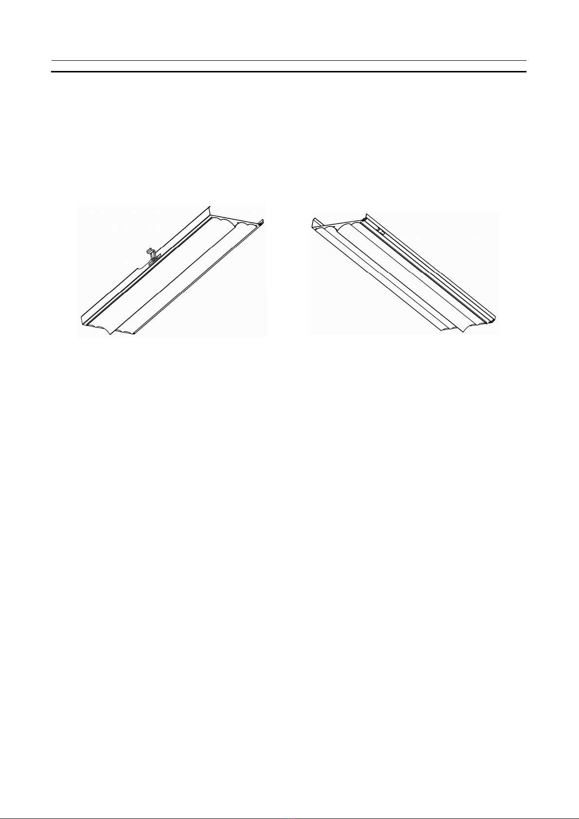
a) b)
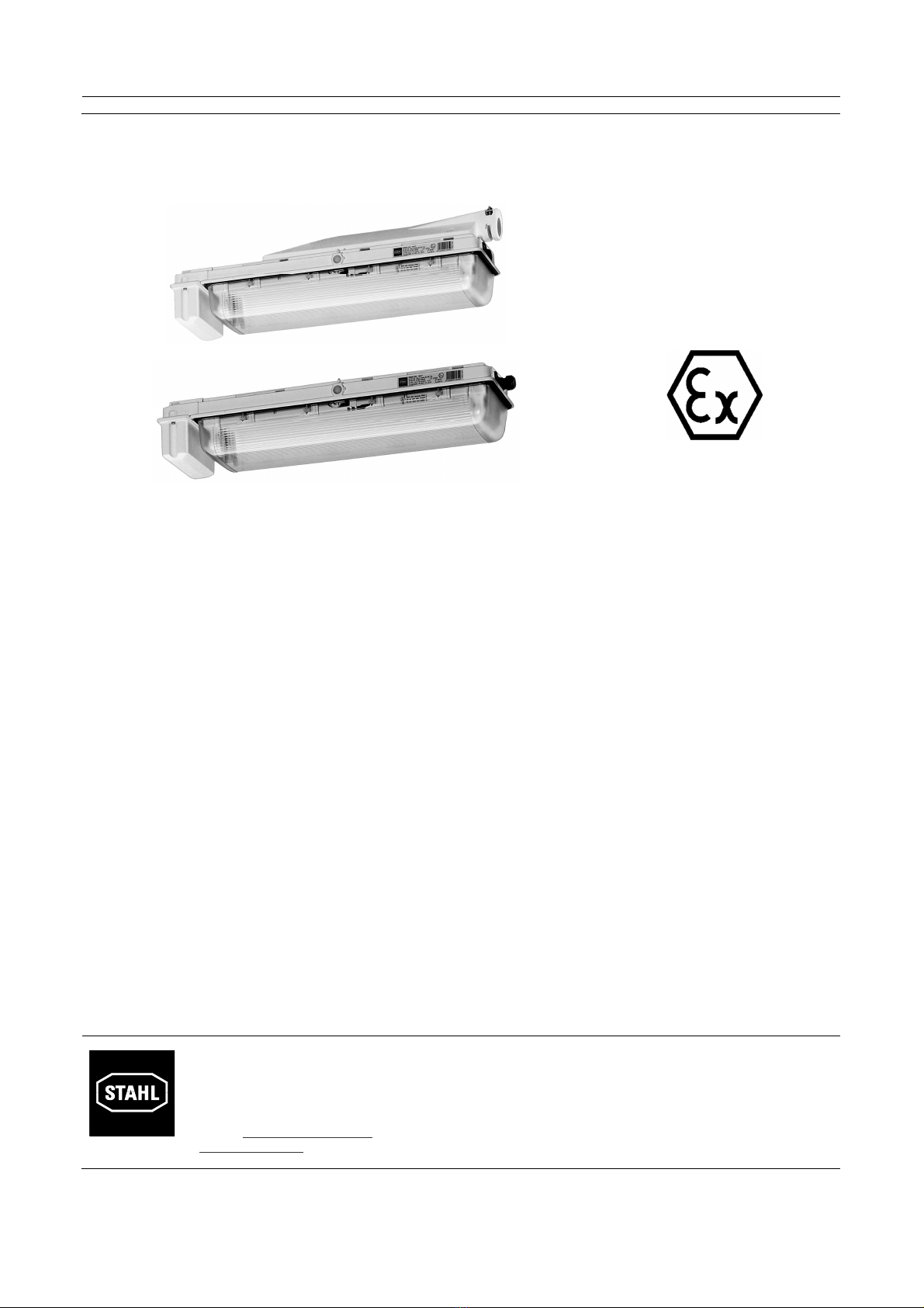
Zusatzreflektoren, tief – breitstrahlend
b)
Additional reflectors (concentrated/
broader lighting b)
Réflecteurs additionnels, éclairage
étroit-large b)
Der hochglanzeloxierte Zusatzreflektor (b)
wird auf den vorhandenen Reflektor aufge-
bracht.
The additional extra-bright anodised reflec-
tor (b) is mounted on the existing reflector.
Le réflecteur additionnel poli spéculaire et
anodisé (b) est monté sur le réflecteur
existant.
Als Ersatzteil zur nachträglichen Montage
wird der vorhandene Reflektor entfernt und
dafür der auf einem Standardreflektor mon-
tierte Zusatzreflektor angebracht. Hierzu
kann der Standardreflektor sehr einfach
aus den Scharnierstiften gedrückt werden
und umgekehrt der neue Reflektor einge-
drückt werden.
The existing reflector, which may serve as
a spare part for later installation, is re-
moved and replaced by the additional re-
flector mounted on a standard reflector. For
this, the standard reflector can be very
easily pressed out of the hinge pins and
the new reflector can be pressed in.
Le réflecteur existant, qui servira de pièce
de rechange lors d’un montage ultérieur,
est enlevé et remplacé par le réflecteur
additionnel monté sur un réflecteur stan-
dard. Pour faire cela, il est très facile de
faire sortir le réflecteur standard des gonds
à charnière et d’y pousser le nouveau
réflecteur.
4.3 Netzanschluss 4.3 Mains connection 4.3 Raccordement au secteur
Maximale Klemmmöglichkeit der An-
schlussklemmen beachten.Bei den Stan-
dardklemmen (Punkt 4.3.1) dürfen 2 Leiter
pro Klemmstelle geklemmt werden (Durch-
schleifen).
Note the limits that have to be observed
with the connection terminals.
2 conductors may be clamped per clamp-
ing point (looped wiring) on the standard
terminals (point 4.3.1).
Respecter la capacité de serrage maximale
des bornes de raccordement. Ne pas bran-
cher plus de 2 conducteurs par emplace-
ment (raccordement en boucle).
Die Phase L dient als Ladephase für die
Batterie. Sie ist immer an die ungeschal-
tete Phase des Netzes anzuschließen,
vor dem Lichtschalter, jedoch nach der
Sicherung. Die Phase L liegt bei ausge-
schaltetem Lichtschalter immer dadurch
an Spannung.
Phase L acts as the charging phase for
the battery. It must always be connected
to the unswitched phase of the mains
supply, before the light switch but after
the fuse. This means that Phase L is
always connected to the voltage supply
when the light switch has been turned
off.
Le conducteur de phase L a pour but de
charger de la batterie. Il doit toujours
être branché sur la phase en amont de
l’interrupteur mais en aval du fusible de
protection. Le conducteur L reste ainsi
sous tension même si l’interrupteur de
commande est coupé.
Die Phasen L und L’ müssen immer
gleichphasig angeschlossen sein.
Phase L and L’ must always be connect-
ed cophasally.
Les conducteurs L et L‘ doivent tou-
jours être raccordés sur la même phase
Schließen des Batteriestromkreises
:
Closing the battery current circuit
:
Fermeture de circuit
batterie
:
Der Batteriestromkreis ist aus Trans-
portgründen geöffnet (siehe auch
Schaltplan Punkt 8). Batteriestecker
innerhalb des Batteriegehäuses
stecken.
The battery current circuit is discon-
nected for transport reasons (see wiring
diagram point 8). Connect the battery
plug within battery housing.
Le circuit batterie est ouvert pour des
raisons liées au transport (cf. schéma
électrique point 8). Brancher le connec-
teur à l'intérieur le boîtier de la batterie!
Betriebsanleitung
Operating instruction
Mode d‘emploi
ID: 169701/6008611300/R. STAHL/2013-02-05/de-en-fr-06
11
Beachten: Note: Attention:
•
Die Klemmung an der “Ex e“ Klemme
muss sehr sorgfältig durchgeführt wer-
den.
•
Keine Isolierung des Leiters mit unter-
klemmen!
•
Leiter nicht vertauschen
•
Leiter muss fest angeklemmt sein, d.h.,
die Schrauben fest anziehen und prü-
fen!
•
Klemmabdeckung muss zum Anklem-
men der Leiter nicht entfernt werden!
•
Durch eine geeignete Auswahl der
verwendeten Leitungen sowie durch
die Art der Verlegung ist sicherzustel-
len, dass die maximal zulässigen Lei-
tertemperaturen nicht überschritten
werden!
•
dass der Batteriestromkreis ge-
schlossen ist, Batteriestecker im Batte-
riegehäuse stecken! (siehe Schaltplan
Pkt. 8)
•
Clamping at the “Ex e“ terminal must be
done very carefully!
•
Do not clamp any part of the conductor
insulation!
•
Do not transpose the conductors!
•
The conductor must be firmly clamped,
i.e. the screw must be screwed tight and
tested!
•
The terminal covering must not be re-
moved in order to clamp the conductor!
•
Selecting suitable leads and the method
of installation to be used will ensure that
the maximum conductor temperatures
permissible are not exceeded.
•
Make sure that the battery current circuit
is connected; connected the battery plug
in the battery housing (see wiring dia-
gram point 8)!
•
Le serrage à la borne “Ex e“ doit être
effectué avec beaucoup de soin!
•
Ne pas coincer l’isolant du fil conduc-
teur lors du serrage!
•
Ne pas confondre les fils conducteurs!
•
Les fils conducteurs doivent être fer-
mement connectés : bien serrer les vis
et contrôler le serrage!
•
La couverture des bornes ne doit pas
être retirée pour le serrage des fils
conducteurs!
•
S’assurer que les températures maxi-
males admissibles des conducteurs ne
soint pas dépassées en selectionneant
de manière appropiée les câbles utili-
sés et le type de pose.
•
Cicuit accumulateur fermé – Brancher
le connecteur dans le boîtier accumula-
teur! (cf. schéma électrique point 8).
4
.3.1
Standardklemmanschluss
4
.3.1
Standard clamp connection
4
.3.1
Raccordement par bornes sta
n-
dard
4-Leiter Anschluss
4-cable connection
Raccordement à 4 fils
6-Leiter Anschluss
6-cable connection
Raccordement à 6 fils
Netzanschluss
Dead-end wiring
Câblage en ligne
Durchschleifen
Looped-wiring
Câblage en ligne
L2, L3 = Phase
N = Neutralleiter/neutral/neutre
PE = Schutzleiter/earth/terre
L’ = geschaltete Phase/switched phase/phase branchée
L1 = Ladephase/charging phase/phase pour la charge
L’ und L1 müssen gleiches Potential haben
L' and L1 must have same potential
Des L'et L1 doivent avoir le même potentiel
Betriebsanleitung
Operating instruction
Mode d‘emploi
ID: 169701/6008611300/R. STAHL/2013-02-05/de-en-fr-0612
Achtung:
Durchverdrahtung mit 2,5 mm² Querschnitt
für max. 16 A
Note:
The through-wiring with a cross-section of
2,5 mm² is rated for max. 16 A
Attention:
Câblage en ligne 2,5 mm² section pour
16 A max.
Durchverdrahtung (4 Leiter)
through-wiring (4 wires)
câblage en ligne (4 3 fils)
Durchverdrahtung (6 Leiter)
through-wiring (6 wires)
câblage en ligne (à 6 fils)
4.3.2 Schraubenlose Federklemmung 4.3.2Screwless clamping 4.3.2 Raccordement par bornes sans
vis
4-Leiter Anschluss
4-cable connection
Raccordement à 4 fils
6-Leiter Anschluss
6-cable connection
Raccordement à 6 fils
L2, L3 = Phase
N = Neutralleiter/neutral/neutre
PE = Schutzleiter/earth/terre
L’ = geschaltete Phase/switched phase/phase branchée
L1 = Ladephase/charging phase/phase pour la charge
L’ und L1 müssen gleiches Potential haben
L' and L1 must have same potential
Des L'et L1 doivent avoir le même potentiel
Anschlussmöglichkeiten, Durchschleifen
und Durchverdrahtung siehe oben.
Es stehen pro Phase 2 - 3 freie Klemm-
stellen zur Verfügung, pro Klemmstelle
darf nur ein Leiter eingeführt werden.
Possible connections, looped wiring and
through-wiring: see above.
2 - 3 free clamping points are available per
phase; only one conductor may be attached
per clamping point.
Pour les possibilités de raccordement, le
raccordement en boucle ou en ligne, se
référer voir en haut.
Le luminaire dispose de 2 - 3 bornes
libres par phase, utiliser un seul conduc-
teur par borne.
Betriebsanleitung
Operating instruction
Mode d‘emploi
ID: 169701/6008611300/R. STAHL/2013-02-05/de-en-fr-06
13
Schraubenloses Federklemmsystem
1. Schraubendreher bis zum Anschlag in
die Betätigungsöffnung einführen.
Insert a screwdriver into the actuation
opening until the stop is reached.
Introduire le tournevis au maximum
dans l’orifice d’actionnement.
Screwless clamping system
2. Die Schraubendreherklinge hält die
CAGE CLAMP-Feder selbsttätig geöff-
net, so dass der Leiter eingeführt wer-
den kann.
The blade of the screwdriver automati-
cally keeps the CAGE clamping spring
open, so that the conductor can be in-
serted.
La lame du tournevis maintient la borne
“CAGE Clamp“ ouverte automatique-
ment, permettant ainsi l’introduction du
conducteur.
Système de connexion sans vis
3. Schraubendreher herausziehen der
Leiter ist sicher geklemmt.
Remove the screwdriver – the conduc-
tor is clamped securely.
Retirer le tournevis – Le conducteur est
serré en toute sécurité.
4.4 Kabeleinführung 4.4 Cable entry 4.4 Indroduction du câble
Die Standardleuchte ist immer mit 3 Ein-
führungsbohrungen M25 versehen und mit
1 Kabeleinführung und 2 Verschlussstopfen
bestückt.
The standard light fitting is always provided
with 3 M25 lead-in holes, one cable entry
and 2 sealing plugs.
La lampe standard est toujours équipée de
3 orifices d'entrée M25, d'une entrée de
câble et de deux bouchons de fermeture.
Beachten:
•
Kabeleinführung und Verschlussstop-
fen können untereinander vertauscht
werden.
Notes:
•
The cable entries and sealing plugs
can be interchanged.
Attention :
•
L'entrée de câble et les bouchons de
fermeture peuvent être intervertis
•
Klemmbereich der Kabeleinführung mit
dem Durchmesser des einzuführenden
Kabels überprüfen.
•
Check the cable entry clamping area
against the diameter of the cable to be
brought in.
•
Vérifier la plage de serrage de l'entrée
de câble avec le diamètre du câble à
introduire
•
Druckschraube der Kabeleinführung
fest anziehen.
•
Tighten the cable entry screw fully
•
Serrer fermement la vis de pression de
l'entrée de câble
•
Alle nicht benutzten Öffnungen mit
bescheinigtem Verschlussstopfen ver-
schließen.
•
All unused opening must be close
d
with certified plugs.
•
Boucher l'ensemble des ouvertures
non utilisées à l'aide de bouchons de
fermeture homologués
•
Nach der Installation Bauteile und
Kabeleinführung auf Dichtheit überprü-
fen (
≥
IP 54)
•
Test the components and cable entry
for ingress protection after installation
(
≥
IP 54).
•
Après l'installation, contrôler l'étanchéi-
té des composants et de l'entrée de
câble (
≥
IP 54)
•
Metall-Kabeleinführung ist über eine
Metalladapterplatte bzw. Metalladapter
mit dem innenliegenden Schutzleiter-
system >PE-Klemme< zu verbinden,
um Potentialunterschiede zu vermei-
den.
•
The metal cable entry must be con-
nected to the internal earth system
>PE-terminal< using a metal adapter
plate, to avoid difference in potential.
•
L'entrée de câble métallique doit être
reliée par l'intermédiaire d'une plaque
adaptatrice métallique au système de
protection interne >borne PE<, afin
d'éviter des différences de potentiel.
>>IP-Schutzart ist Teil der Explosions-
schutz-Maßnahme<<
>>IP protection type is part of the explosion
protection measures<<
>>Le degré de protection IP est partie inté-
grante des mesures antidéflagrantes<<
Betriebsanleitung
Operating instruction
Mode d‘emploi
ID: 169701/6008611300/R. STAHL/2013-02-05/de-en-fr-0614
Bei Außenmontage empfehlen wir den
Einsatz eines Klimastutzens der Fa.
STAHL, Typ 8162. Er kann anstelle eines
Verschlussstopfens eingesetzt werden
(M25). Der Klimastutzen kann an beliebiger
Stelle montiert werden und hält die Schutz-
art IP64 ein.
On external fittings we recommend the use
of a Type 8162 breather from STAHL Co.
It can be used instead of a plug (M25) and
can be fitted at any point, maintaining
protection type IP 64.
Dans le cadre de montages extérieurs,
nous conseillons l'installation d'un raccord
climatique de la société STAHL, type 8162,
qui peut être monté en lieu et place d'un
bouchon de fermeture (M25). Le raccord
climatique peut être installé à l'endroit sou-
haité et maintient le degré de protection IP
64.
Bei schräger Leuchtenmontage befindet
sich die günstigste Position am unteren
Leuchtenniveau.
The most favourable Position on skew
mounting is located the lower light fitting
housing.
En cas de feux de montage biseauté se
trouve la position la plus favorable au ni-
veau inférieur de luminaires.
4.5 Einsetzen und Austausch von
Lampen
4.5 Fitting and removing lamps 4.5 Mise en place et remplacement
des tubes
Lampen mit Zweistiftsockel G13 Lamps with bi-pin base G13 Tubes à culot 2 broches G13
Beide Lampensockel der Lampe in die
Fassungsführungsschlitze bis zum An-
schlag einsetzen. Die Lampe durch rechts-
oder linksdrehen in Betriebsstellung brin-
gen.
Insert both the lamp bases into the holder
guide slots until the stop is reached. Move
the lamp to its operating position by turn-
ing it to the right or the left.
Engager les 2 culots du tube dans les
fentes de guidage de la douille jusqu’en
butée. Amener le tube en position de ser-
vice en le tournant vers la droite ou vers la
gauche.
Beachten: Important notes: Attention:
•
Die Lampensockel müssen unbe-
schädigt sein.
•
The lamp bases and pins must be
undamaged.
•
Les culots du tube ne doivent pas
présen-ter de dommages.
•
Die Fassungen haben einen federn-
den Längenausgleich von je 2,5 mm.
•
The holders have a spring-loaded
length adjustment facility of 2,5 mm
each.
•
Les douilles sont chacune munies
d’un système de compensation de
longueur par ressort de 2,5 mm.
•
Auf Sitz der Lampe achten; nach dem
Drehen ist der Lampensitz verriegelt.
•
Make sure that the lamp has been
fitted properly. When it has been
turned, the lamp is locked in position.
•
Vérifier le positionnement correct du
tube; après rotation, le tube doit être
verrouillé.
Betriebsanleitung
Operating instruction
Mode d‘emploi
ID: 169701/6008611300/R. STAHL/2013-02-05/de-en-fr-06
15
5 Notlichtfunktion 5 Emergency light function 5 Fonction éclairage de secours
5.1 Betriebsarten 5.1 Operating modes 5.1 Modes de fonctionnement
Bei Netzausfall wird die Sicherheitslampe
(grün markiert) im Notlichtbetrieb aus der
Batterie gespeist.
The safety lamp (marked green) is powered
by the battery in the emergency light oper-
ating mode when there is an interruption in
the mains power supply.
En cas de panne secteur, la lampe (mar-
quage en vert) est alimentée en mode
secours par l’accumulateur.
Sollte diese Sicherheitslampe ausfallen,
wird der Betrieb mit der zweiten Lampe
fortgesetzt.
In case of defective safety lamp, the
operation will continue with the second
lamp.
En cas de lampe défectueuse de sûreté,
l'opération continuera la deuxième
lampe.
Ausführung
Dauerschaltung oder Dauerschaltung mit
schaltbarer Notlichtblockierung sowie in
Bereitschaftsschaltung.
Bei der Auslieferung ist die Leuchte für
Dauerschaltung bzw. Bereitschaftsschal-
tung verdrahtet. Der Anwender kann vor
Ort durch Lösen der Brücke an Klemme
9/10 der Notlichtelektronik und durch den
Anschluss eines Fernschalters F die Dau-
erschaltung mit Notlichtblockierung selbst
bestimmen (siehe unter „b“) .
Version
Maintained operation or maintained opera-
tion with switchable emergency light block-
ing as well as stand-by operation
On delivery, the light fitting is wired for main-
tained operation or stand-by operation. By
removing the jumper at terminal 9/10 of the
emergency light electronics and connecting
an remote switch (F) the respective user
can switch on or off non-maintained opera-
tion himself (see “b”)..
Version
Connexion permanente ou en connexion
permanente avec possibilité de blocage de
la fonction secours ainsi que couplage
d’alerte. A la livraison le luminaire est câblé
pour connexion permanente ou que cou-
plage d’alerte. En supprimant le pont à la
borne 9/10 de l’électronique mode secours
et raccordant un interrupteur F à distance,
l’utilisateur sur place lui-même peut mettre
le mode secours en ou hors service (voir
"b").
a) Dauerschaltung a) Maintained operation a) Connexion permanente
Bei Netzausfall wird die Leuchte aus der
Batterie gespeist, unabhängig von der
Schaltstellung des Lichtschalters.
If the mains power supply fails, the light
fitting is supplied by the battery, no matter
what switching position the light switch is in.
En cas de coupure de courant sur le ré-
seau, le luminaire est alimenté par
l’accumulateur, ceci indépendamment de
la position de l’interrupteur de commande.
S = Lichtschalter/Light switch/commutateur
b) Dauerschaltung mit schaltbarer Not-
lichtblockierung
b) Maintained emergency light operation
with switchable emergency light blocking
b) Connexion permanente avec possibili-
té de blocage de la fonction secours
Bei Ausfall der Stromversorgung für die
Allgemeinbeleuchtung schaltet die Leuchte
automatisch auf Notlichtbetrieb, wenn der
Fernschalter eingeschaltet ist. Über die
Fernschaltung kann die Notlichtleuchte
zentral “betriebsbereit“ bzw. “ nicht be-
triebsbereit“ geschaltet werden, zum Bei-
spiel in Abhängigkeit von Betriebszeiten.
If the power supply for the general lighting
system fails, the light fitting switches to
emergency light operation automatically if
the remote switch is switched on. The
emergency light fitting can be switched to
“ready for operation“ or “not ready for oper-
ation“ via the external switch, e.g. depend-
ing on plant operating hours.
En cas de coupure de courant sur le circuit
d’éclairage général, le luminaire passe
automatiquement en “secours“ si
l’interrupteur F placé à distance est sur
“En service“. Par l’intermédiaire de cet
interrupteur il est possible de mettre le
mode de fonctionnement “Secours“ en ou
hors service, selon par exemple les ho-
raires de fonctionnement d’un atelier.
Die Fernschaltung erfolgt über einen ex-
ternen Schalter [F].
The remote switching is realized by an
external switch (F).
Sélection du mode de fonctionnement par
l’interrupteur F à distance avec un contact:
Betriebsanleitung
Operating instruction
Mode d‘emploi
ID: 169701/6008611300/R. STAHL/2013-02-05/de-en-fr-0616
Kontaktschließer, potentialfrei
Kontakt offen = nicht betriebsbereit
Kontakt geschlossen = betriebsbereit
NO contact, potential-free
Contact open = not ready for operation
Contact closed = ready for operation
NO libre de tout potentiel.
Contact ouvert = Secours hors service
Contact fermé = Mode de fonctionnement
“Secours en service“,
c’est-à-dire opérationnel
dès l’apparition d’une
coupure de courant
Punkt-zu-Punkt-Verbindung Point to point connection Liaison point à point
Linienverbindung Line connection Connexion en ligne
Der Fernschalter ist nicht galvanisch getrennt und wird
an den Klemmen 9 (BAT-) und 10 (Fernschalter) ange-
schlossen.muss mindestens 1 A DC schalten können.
The remote switch is not galvanically disconnected and
has to connected at the cages 9 (BAT-) and 10 (remote
switch). The external switch has to switch minum 1 A
DC.
L’interrupteur distant n’est pas isoler galvaniquement, il
se connecte via la borne 9 (Bat-) et 10 (interrupteur
distant). L’interrupteur distant doit avoir un pouvoir de
coupure d’au moins 1A DC.
Max. Anzahl/max. number/nombre maximum 6043/7: 50
Max. Kabellänge/max. cable length/maximum longleur du câble L1: 500 m
Min. Kabelquerschhnitt/min. cable cross section/coupe transversale du câble minium: 1,5 mm², Cu
Max. Anzahl/max. number/nombre maximum: 30
Max. Kabellänge/max. cable length/maximum longleur du câble L1: 100 m
Max. Kabellänge/max. cable length/maximum longleur du câble L2: 50 m
Max. Kabellänge/max. cable length/maximum longleur du câble L3: 500 m
Min. Kabelquerschhnitt/min. cable cross section/coupe transversale du câble minimum: 1,5 mm², Cu
Betriebsanleitung
Operating instruction
Mode d‘emploi
ID: 169701/6008611300/R. STAHL/2013-02-05/de-en-fr-06
17
Achtung:
Befindet sich die Leuchte im Notlicht-
betrieb, d. h. es liegt keine Netzspan-
nung zwischen L und N an, hat das
Öffnen des Fernschalters keine Aus-
wirkungen auf den Notlichtbetrieb.
Bei der Zusammenschaltung mehrerer
Leuchten - Fernschalter unbedingt nach
Skizze verdrahten – ansonsten ist eine
einwandfreie Funktion nicht gewährleistet.
Beim Verlegen dieser Steuerleitung zu-
sammen mit Starkstromkabel (Kabelkanal)
abgeschirmte Steuerleitung verwenden,
um eine Spannungsinduzierung zu verhin-
dern.
Look out:
Is the light fitting in emergency opera-
tion that means there is no main volt-
age between L and N, the opening of
remote switch has no effects to emer-
gency light operation.
In case of interconnection of several light
fittings wire remote switch absolutely due
to the sketch – otherwise a proper func-
tioning cannot be guaranteed. Please use
screened trip line laying this trip line to-
gether with power current cable (cable
duct) – in order to avoid voltage induction.
Attention:
Si le BAES se trouve en état de se-
cours, cad qu’il n’y a pas d’alimentation
électrique entre les bornes L et N.
L’ouverture de l’interrupteur distant
n’aura pas d’influence sur le BAES.
En cas d’une interconnexion de plusieurs
lampes s.v.p. câblez absolument
l’interrupteur à distance selon l’esquisse –
autrement un fonctionnement propre ne
sera pas garanti. En posant cette ligne
pilote avec le câble d’énergie (caniveau de
câbles) utilisez la ligne pilote protégée
pour éviter une induction de tension.
c) Bereitschaftsschaltung c) Stand-by operation c) Couplage d’alerte
Die Leuchte ist im Normalbetrieb nicht
eingeschaltet. Sie schaltet sich bei Netz-
ausfall automatisch ein. Nur die Ladepha-
se L1 – gleichzeitig auch Netzüberwa-
chungsleiter – muss an die Anschluss-
klemme L1 angeschlossen werden.
In normal operation, the light fitting is not
swiched on. It connects automatically in
case of a mains power supply failure. Only
L1 charging phase –also the mains moni-
toring conductor – has to be connect to the
L1 terminal.
Le luminaire n’est pas allumé pendant
l’opération normale. Il s’allume automati-
quement en cas de panne de secteur.
Uniquement la phase de charge L1 –
simultanément avec le conducteur de
surveillance du réseau - doit être branchée
sur la borne L1.
5.2 Notlichtelektronik 5.2 Electronic emergency light control
unit
5.2 Electronique de secours
Die Notlichtelektronik ist zusammen mit
dem elektronischen Vorschaltgerät in
einem Gehäuse 6043 eingebaut. Damit
wird die Sicherheitslampe (grüne Markie-
rung) im Netz- und Batteriebetrieb ver-
sorgt. Bei 2-lampiger Leuchte wird die
zweite Lampe ebenfalls von diesem Ver-
sorgungsgerät betrieben.
The electronic emergency light control unit
is installed in the resistant enclosed hous-
ing 6043 together with the electronic bal-
last. This means that the safety lamp
(marked green) is supplied in mains and
battery operation. In case of a two lamps
light fitting, the second lamp is also oper-
ated by this supply device.
L’électronique de secours est montée avec
le ballast électronique dans le boîtier 6043
encapsulé et résistant. La lampe de sécu-
rité (marquage en vert) est alimentée à la
fois par le secteur et par l’accumulateur.
En cas d’un luminaire à deux lampes, la
deuxième lampe est également actionnée
par le même appareil d’alimentation.
Betriebsanleitung
Operating instruction
Mode d‘emploi
ID: 169701/6008611300/R. STAHL/2013-02-05/de-en-fr-0618
5.2.1 Notlichtbetriebsdauer 5.2.1 Emergency light duration 5.2.1 Autonomie de secours
Die Betriebsdauer im Notlichtbetrieb ist
abhängig von der Batteriekapazität, sowie
entsprechender Drahtbrücke
The period of operation in emergency light-
ing mode depends on the battery capacity
and an appropriate wire bridge.
L’autonomie en mode secours dépend de
la capacité de l’accumulateur et des
shunts utilisés.
Betriebsdauer
Operating time
Autonomie
Batterie
Battery
Accumulateur
Klemmenbrücke
Terminal jumper
Shunt
Lichtleistung
Luminous power
Rendement
17/18 W 32/36 W
1,5 h 7 Ah - 100 % 60 %
3 h mit/with/avec 60 % 30 %
mit Brücke: 3 h
with jumper 3 h
avec jumper 3 h
ohne Brücke 1,5 h (Auslieferungszustand)
without jumper 1,5 h (delivery state)
sans jumper 1,5 h (état à la livraison)
5.2.2 Funktion/Überwachung 5.2.2 Function/Monitoring 5.2.2 Fonctionnement/surveillance
Nach Ausfall der Netzversorgung schaltet
die Elektronik auf Batteriebetrieb.
The electronics switch to battery operation
when the mains supply fails.
En cas de panne de l’alimentation secteur,
l’électronique bascule en mode accumula-
teur.
Ein wöchentlicher Funktionstest wird
automatisch durchgeführt.
Hinweis: Die erste Funktionsprüfung wird
1 Stunde nach Inbetriebnahme durchge-
führt und ist der Beginn der Zeitrechnung
für alle nachfolgenden Funktionstests!
Der Notlichtbetriebsdauertest wird 1 x
jährlich durchgeführt. Dabei wird die Batte-
rie auf Entladeschlussspannung entladen.
Dadurch entfällt ein jährliches Entladen zur
Wartung der Batterie. Der Test gilt als
bestanden, wenn beim Entladen der Batte-
rie die eingestellte Notlichtbetriebsdauer
überschritten wird. Befindet sich die
Leuchte durch einen Netzausfall länger als
die eingestellte Notlichtbetriebsdauer im
Notlichtbetrieb, so wird dies als Notlicht-
brenndauertest gewertet. Das Zeitintervall
wird danach wieder auf ein Jahr gesetzt.
A weekly function test is carried out au-
tomatically.
Note: The first functional test is carried out
1 hour after putting into operation and is
the start for calculating the times of all
subsequent function tests.
The emergency light continuous opera-
tion test is carried out once per year
. In the
process, the battery will discharge on cell-
end voltage. A yearly discharging for the
maintenance of the battery is not re-
quired.The test is passed, if the timed
emergency light operation is exceed by
discharging of battery. Is the light fitting by
a power failure longer than the timed emer-
gency light continous operation in emer-
gency operation so will this noticed as an
emergency light continous operation test.
After that, the time interval is set for a year.
Un test de fonctionnement hebdoma-
daire est exécuté automatiquement.
Remarque: Le premier test fonctionne-
ment est effectué 1 heure après de la mise
en service et est le début pour calculer les
temps de toute autre test de fonctionne-
ment.
Le test automatique du BAES est effec-
tué une fois par an. Pendant ce test la
batterie est ramener jusqu’au minimum de
décharge. Ce test exclus une autre vérifi-
cation de la batterie. Le test est positif, si
la durée nominale de fonctionnement du
BAES est dépassée. Si le BAES se trouve
en conditions de secours suite à une cou-
pure électrique, ceci est validé comme
test. Le compteur de test se trouve réinitia-
liser pour un an.
Der erste Betriebsdauertest wird zufällig
bestimmt und liegt in einem Zeitfenster
von 1 Tag bis 44 Tagen.
The first continuous test is determined by
chance and lies in a period of 1 day to 44
days.
Le premier test est déterminé par hasard
et il est dans une fenêtre de temps de 1
jour jusqu'à 44 de jours.
Der automatische Notlicht-Brenndauer-
Test ist nur bei Plusgraden (> 0°C) sinn-
voll, da bei Minusgraden (< -5°C) aus
physikalischen Gründen kaum noch eine
Ladung stattfindet.
The automatic emergency light continuous
“on“ test is only useful with ambient tem-
peratures in the positive range (> 0°C),
because at negative temperatures (< -5°C)
virtually on charging tales place for physical
reasons.
Le test d’autonomie de l’éclairage de se-
cours n’est judicieux que pour les tempé-
ratures ambiantes positives (> 0°C), étant
donné que pour les températures néga-
tives (< -5°C) la charge de la batterie est
quasi inexistante pour des raisons phy-
siques.
Durch das damit eingeschränkte Kapazi-
tätsvermögen des Notlichtakkus würde der
Notlicht-Brenndauertest zu fehlerhaften
Ergebnissen führen.
The thereby reduced emergency light bat-
tery capacity would the emergency light
continuous test lead to incorrect results.
La capacité ainsi réduite de la batterie de
secours pourrait le test d’autonomie en
fonctionnement de secours mener à des
résultats incorrects.
Betriebsanleitung
Operating instruction
Mode d‘emploi
ID: 169701/6008611300/R. STAHL/2013-02-05/de-en-fr-06
19
Hinweise Notes: Remarques:
1) Durch das Öffnen der Notlichtleuchte
verschieben sich die nächsten Funkti-
ons- und Betriebsdauerprüfungen um
den Zeitraum, den die Leuchte geöff-
net ist, da das Notlichtgerät während
dieser Zeit ohne Energieversorgung
ist.
2) Während der Funktions- und Betriebs-
dauerprüfungen leuchtet die Leuchte,
auch wenn sie ausgeschalten ist.
1) Opening the emergency light fitting
postpones the following function tests
and continuous “on” tests by the period
of time the light fitting is open, as the
emergency light device is disconnected
from energy supply during this period.
2) Even through being switched off, the
light fitting shines during function tests
and continuous “on” tests.
1) L’ouverture du luminaire de secours
décale les tests de fonctionnement et
d’autonomie suivants de la période
pendant laquelle le luminaire était ou-
vert, parce que l’appareil de lumière
de secours est déconnecté de
l’alimentation en courant pendant ce
temps.
2) Le luminaire est allumé pendant les
tests de fonctionnement et
d’autonomie, même s’il est mis hors
circuit.
Aktivieren/Deaktivieren des Notlicht-
brenndauertest
Je nach Typ der Leuchte ist der automati-
sche Betriebsdauertest aktiviert
(6008…-….-…7)
oder deaktiviert
(6008…-….-…8)
Dies kann nach folgendem Schema inner-
halb von 60 Sekunden nach Inbetrieb-
nahme umgeschaltet werden.
Activating/deactivating the emergency
duration test
Depending on the type of the luminaire the
endurance test might be activated
(6008…-….-…7)
or not activated
(6008…-….-…8)
This can be changed after the following
scheme within 60 seconds after putting
into operation.
Activation/Désactivation du Test
En fonction du luminaire le test automa-
tique est activé
(6008…-….-…7)
Ou désactivé
(6008…-….-…8)
Ce dernier peut être régler (selon sché-
mas) dans les 60 Secondes qui suivent la
mise en service.
t
F
60s
t
S
3...8s
t
H
3...8s
t
L
3...8s
t
E
>8s
Nach erfolgreichem Umschalten wird dies
durch ein schnelles Blinken der LED für 30
Sekunden angezeigt.
After changing successfully this is shown
to the LED by a flashing fast for 30 se-
conds
Après un réglage, ce dernier est acquitté
par un clignotement rapide de la LED.
LED- Anzeige LED display Affichage par LED
(Betriebszustand der Leuchte) (Operation status of light fitting) (Ètat opérationnel de luminiare)
tF
L1
L
I
tHtHtH
•
tLtE
tS
L – Ladephase/ charging phase/phase pour la charge
L’ – geschaltete Phase/switched phase/phase branchée
Betriebsanleitung
Operating instruction
Mode d‘emploi
ID: 169701/6008611300/R. STAHL/2013-02-05/de-en-fr-0620
Bei Zuschalten der Netzversorgung In case of connecting main supply Lors de la connexion de l‘alimentation
Initialisierung für 30 Sekunden mit folgen-
den Anzeigen:
Initializing for 30 seconds with follow indica-
tions:
Initialisation en 30 secondes avec
l’affichage suivant:
0 s – 10 s grüne LED ein
(Funktion der LED)
0 s – 10 s green LED on
(function of LED)
0 s – 10 s 0 s – 10 s LED verte allumer
(Fonction de la LED)
10 s – 20 s rote LED ein
(Funktion der LED)
10 s – 20 s red LED on
(function of LED)
10 s – 20 s 10 s – 20 s LED rouge allu-
mer (Fonction de la LED)
20 s – 30 s Anzeige Zustand
Notlichtbetriebsdauertest
20 s – 30 s Display condition of emer-
gency light continous oper-
ation test
20 s – 30 s 20 s – 30 s Affichage de l’état
du test BAES
Notlichtbetriebsdauertest aktiv
= blinken grüne LED
Emergency light continous operation test
active = blinking green LED
Test de fonctionnement du BAES actif =
LED verte clignotant
Notlichtbetriebsdauertest nicht aktiv
= beide LED aus
Emergency light continous operation test
inactiv = both LED off
Test de fonctionnement du BAES non actif
= les 2 LED éteint
Danach schaltet die LED- Anzeige in Be-
triebsmodus und zeigt folgende Betriebs-
zustände:
After that, the LED display is change into
operating mode and shows following oper-
ating statuses:
Ensuite le LED bascule en fonctionnement
et annonce les états suivants :
Lampenfehler Lamp errors Erreurs de lampes
Wird ein Lampenfehler (Lampe defekt oder
Lampe am Lebensdauerende) erkannt, so
wird dies durch ein rotes Blitzen der LED
signalisiert.
If a lamp fault (lamp defect or reached end
of life) is recognized, then is this signalled
by a flashing of the red LED.
Si une erreur de la lampe (le défaut de la
lampe ou la lampe à le fin de la vie) est
reconnue, alors ceci, est-il signalé par un
flah du LED rouge.
Durch das Öffnen und Schließen der
Leuchte beim Lampenwechsel wird die
Signalisierung des Lampenfehlers zurück-
gesetzt. Das Notlichtgerät quittiert das
Rücksetzen durch schnellen rot/grünen
Farbwechsel – 5 Sekunden lang. Danach
kommt das grüne Dauerlicht für Ladebe-
trieb der Akkus.
By opening and closing the light fitting
during lamp changes, lamp error signalling
is reset. The emergency light device
acknowledges the reset operation by rapid
red/green colour change for 5 seconds.
Afterwards, the green steady burning light
indicates the battery charging operation.
En ouvrant et fermant le luminaire lors
d’un changement de lampes, la signalisa-
tion des erreurs de lampes est réinitialisée.
L’appareil de lumière de secours confirme
la réinitialisation par des couleurs
rouge/verte changeant rapidement pen-
dant 5 secondes. Ensuite, l’allumage vert
ininterrompu confirme l’opération de
charge de la batterie.
Batteriekapazitätsfehler Battery capacity error Erreur de capacité de la batterie
Genügt die Kapazität des Akkus nicht, um
die 2/3 Nennbetriebsdauer der Notlicht-
leuchte aufrecht zu halten; wird dies durch
rotes Blinklicht der LED angezeigt. Batte-
rietausch muss durchgeführt werden.
If the battery capacity is not sufficient to
maintain 2/3 of the emergency light fitting
nominal operating time, this is indicated by
the red blinker. A battery change has to be
executed.
Si la capacité de la batterie ne suffit pas
pour maintenir 2/3 de l’autonomie nomi-
nale du luminaire de secours, cela est
indiqué par l’allumage feu clignontant. Un
changement de batterie devra être effec-
tué.
Das Zurücksetzen der Anzeige nach Bat-
terietausch muss durch ein bestimmte
Vorgehensweise durchgeführt werden
(siehe Abschnitt 5.4 „Batteriewechsel“).
Resetting the display after battery change
has to be carried out according to a specific
procedure (see chapter 5.4 “battery
change”).
La réinitialisation de l’allumage après le
changement de batterie doit être effectuée
d’après une procédure particulière (cf.
paragraphe 5.4 "remplacement de batte-
rie").
Wird die Anzeige nach dem Batteriewech-
sel nicht zurückgesetzt, so erfolgt nach 36
Stunden automatisch ein Notlichtbetriebs-
dauertest (siehe Punkt 5.2.2). Ist der Be-
triebsdauertest erfolgreich, wechselt die
LED wieder zu grün.
Will the display after changing battery not
reset so follows an automatically emergen-
cy light continous test (see point 5.2.2)
after
36 hours. Is the emergency light continous
test successful the LED change to green.
Si le système n’est pas réinitialiser après
le changement de batterie, un test sera
effectué après 36 heures de fonctionne-
ment (voir point 5.2.2). Si le test est
positif, la LED passe au vert.

This manual suits for next models

1

Other Stahl Light Fixture manuals

Stahl ECOLUX 6608 User manual

Stahl

Stahl ECOLUX 6608 User manual

Stahl 6118/1 Series User manual

Stahl

Stahl 6118/1 Series User manual

Popular Light Fixture manuals by other brands

Energetic Lighting ELYSL-5004 Series installation instructions

Energetic Lighting

Energetic Lighting ELYSL-5004 Series installation instructions

ArtFox Beam 15R extreme manual

ArtFox

ArtFox Beam 15R extreme manual

Dometic Heki 2 de Luxe Installation and operating manual

Dometic

Dometic Heki 2 de Luxe Installation and operating manual

PR Lighting AQUA MARINE 580 BEAM manual

PR Lighting

PR Lighting AQUA MARINE 580 BEAM manual

PELI 9440 user manual

PELI

PELI 9440 user manual

Maxxima MRL-61800CNW user manual

Maxxima

Maxxima MRL-61800CNW user manual

netvox ZC07 user manual

netvox

netvox ZC07 user manual

Blizzard StormChaser Supercell manual

Blizzard

Blizzard StormChaser Supercell manual

Chauvet MiN Spot user manual

Chauvet

Chauvet MiN Spot user manual

thomann STAIRVILLE maTrixx SC-50 LED Effect user manual

thomann

thomann STAIRVILLE maTrixx SC-50 LED Effect user manual

MOLTO LUCE LENS F QUAD Mounting instruction

MOLTO LUCE

MOLTO LUCE LENS F QUAD Mounting instruction

Lightolier Lytespan 8330 specification

Lightolier

Lightolier Lytespan 8330 specification

nordlux Lotus quick start guide

nordlux

nordlux Lotus quick start guide

Lightolier Calculite ProSpec PB4H3870 specification

Lightolier

Lightolier Calculite ProSpec PB4H3870 specification

Creamsource Vortex 8 manual

Creamsource

Creamsource Vortex 8 manual

Lightolier BOWSHIELD “ADA” WALL BRACKET SERIES Instructions for installation

Lightolier

Lightolier BOWSHIELD “ADA” WALL BRACKET SERIES Instructions for installation

Philips Calculite IS-PE instruction sheet

Philips

Philips Calculite IS-PE instruction sheet

Whelen Engineering Company Delta Independence installation guide

Whelen Engineering Company

Whelen Engineering Company Delta Independence installation guide

manuals.online logo
manuals.online logoBrands
  • About & Mission
  • Contact us
  • Privacy Policy
  • Terms and Conditions

Copyright 2025 Manuals.Online. All Rights Reserved.