Stahl Hotronix DUAL Air Fusion User manual

Dual Air Fusion™
O P E R AT O R’ S M A N U A L

Fig.1
S E R V I C E H O T L I N E : 8 0 0 . 7 2 7 . 8 5 2 0
Read all instructions.
Use heat press only for its intended use.
To reduce the risk of electric shock, do not immerse the heat press in water or other liquids.
Never pull cord to disconnect from outlet, instead grasp plug and pull to disconnect.
Do not allow cord to touch hot surfaces, allow heat press to cool completely before storing.
Do not operate heat press with a damaged cord or if the equipment has been dropped or damaged. To reduce
WKHULVNRIHOHFWULFVKRFNGRQRWGLVDVVHPEOHRUDWWHPSWWRUHSDLUWKHKHDWSUHVV7DNHLWWRDTXDOL¿HGVHUYLFH
SHUVRQIRUH[DPLQDWLRQDQGUHSDLU,QFRUUHFWDVVHPEO\RUUHSDLUFRXOGLQFUHDVHWKHULVNRI¿UHHOHFWULFVKRFN
or injury to persons when the equipment is used.
This appliance is not intended for use by persons (including children) with reduced physical, sensory or
mental capabilities, or lack of experience and knowledge, unless they have been given supervision or
instruction concerning use of the appliance by a person responsible for their safety.
Close supervision is necessary for any heat press being used by or near children. Do not leave equipment
unattended while connected.
Burns can occur when touching hot metal parts.
To reduce the likelihood of circuit overload, do not operate other high voltage equipment on the same circuit.
If an extension cord is necessary, then a 20 amperage rated cord should be used. Cords rated for less
amperage may overheat. Care should be taken to arrange the cord so that it cannot be pulled or tripped over.
Important
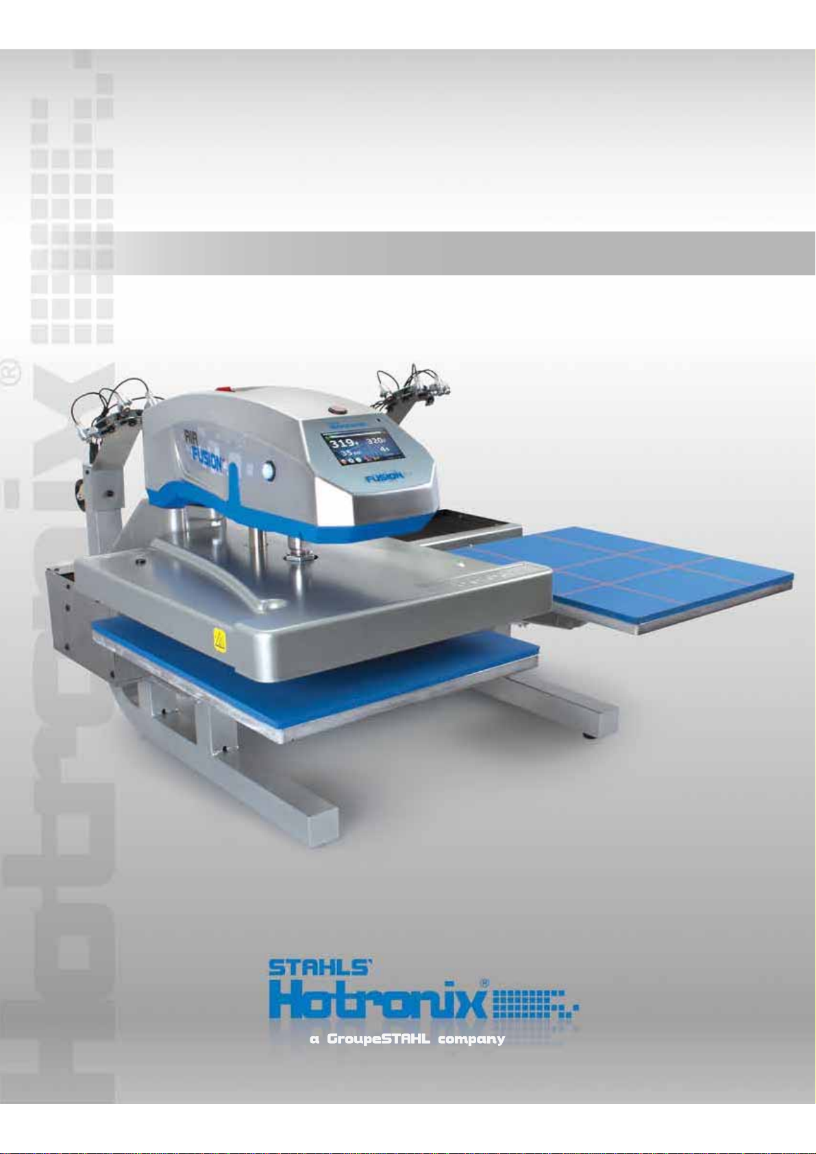
The Hotronix®Dual Air Fusion™is equipped with a Quick Release Button located on the top of the control
housing. When pressed, this button activates a quick release of the heat platen when in the print position and
automatically returns the platen to the “UP” position. Once activated, the button can be reset by pushing it in.
The press will then return to the Normal Operating Mode.
Light on = Normal Operating Mode
Light off = Quick Release Mode
In the event of a loss in air pressure to your machine while the
heat platen is in the down or print mode, remove the opposite
lower platen and push the top of the Dual Air Fusion over to the
open position. (Fig. 1)
1.
2.
3.
4.
5.
6.
7.
8.
9.
10.
11.
12.
13.
When using your heat press, basic precautions
should always be followed, including the following:
Safety Instructions
Product Warranty Registration
Log onto Hotronix.com/registration. You must provide the Hotronix®heat press serial number and model information.

HOTRONIX®DUAL AIR FUSION™
3
H O T R O N I X . C O M
Safety Instructions
Machine View
Touch Screen Guide
Operating Instructions
Connecting the System
Start Up/Shut Down
Print Screen
Passwords
Setup Menu
Preset Setup
Date & Time Setup
Display Setup
Auto On and Off Setup
Passwords Setup
Language Setup
Laser Setup
System Setup
Prepare to Print
Replacing Parts
Electrical Schematic
Contact
2
4
5
6-18
6
7
8-10
10
11-17
11-12
13
13
14
15
16
16
17
18
19-21
22
23
Table of Contents

HOTRONIX®DUAL AIR FUSION™
4
10
12
ON/OFF Switch
Quick Release Button
Touch Screen
Upper Platen
Lower Platen A
Lower Platen B
Base
Platen Release Lever
1
11
2
3
9
8
6
4
13 15
14
16
5
Print Buttons
Casters
Alignment Lasers
(Optional)
Bellow
Circuit Breakers
& IEC Inlet
Air Connect
Air Hose
Foot Pedal
Power Cord
1.
2.
3.
4.
5.
6.
7.
8.
9.
10.
11.
12.
13.
14.
15.
16.
17.
7
17
598101711
7
S E R V I C E H O T L I N E : 8 0 0 . 7 2 7 . 8 5 2 0
Machine View

HOTRONIX®DUAL AIR FUSION™
5
Fig.1
Fig.2
Fig.3
Fig.4
Fig.5
H O T R O N I X . C O M
Navigation
Most screens have a Cancel or Back button to close the current screen
without saving any changes and will return the user to the previous screen.
(Fig.1)
Touch Screen Guide
Some screens may present a list of items. When the list of items is larger
than can be displayed on a single screen, a left and/or right arrow
appears on the left or right side of the screen. Auser can scroll through
the list by making a sweeping gesture across the screen, either left and/or
right, as indicated by the arrows. The user must be touching the screen for
the gesture to be detected. Very fast and very slow gestures may not be
recognized. (Fig.1)
Editing
(GLWDEOH¿HOGVPD\EHGLVSOD\HGLQDQ(GLW%R[$Q(GLW%R[W\SLFDOO\
RYHUOD\VWKHVFUHHQDQGSUHVHQWV¿HOGVDQGRUFRQWUROVEdit Boxes
typically do not have a Back or Cancel button. The Edit Box can be closed
by touching the screen anywhere outside the Edit Box. A Save or Enter
button may be displayed in an Edit Box. Closing the Edit Box without
pressing the Save button will result in the loss of your changes. (Fig.2)
Keypad Display
The Keypad display is used for data entry purposes. This is used to enter
text or numeric data when required. The Keypad provides function keys for
Cancel, Enter and Backspace/Clear (“<”) keys. Also, a mode key may be
present between the Cancel and Enter key. The mode key allows the user
to switch between upper and lower case letters and numeric and
other characters that may be entered using the Keypad. (Fig.4)
Typically, the current value is displayed in the Keypad value display at the
top of the screen. Use the Keypad to change the current value. Use the
Enter key to accept the change or the Cancel key to exit without accepting
the change to the current value. (Fig.4)
The Keypad display is also used for password entry. Password characters
will be displayed with “*” in place of the password value.
,QDGGLWLRQWRHGLWDEOH¿HOGVDQ8S'RZQLFRQPD\EHSURYLGHGWRLQFUHDVH
or decrease values. The Up/Down icon (in most cases) can be held down
to automatically increase or decrease the value. (Fig.3)
Menu Selection
The available Menu Screens are displayed as icon images on the screen.
Touch and release the icon to open the desired Menu Screen. (Fig.5)

HOTRONIX®DUAL AIR FUSION™
6
1.2
1.1
1.3
S E R V I C E H O T L I N E : 8 0 0 . 7 2 7 . 8 5 2 0
Connecting the System
Connect the power cord into the IEC inlet located on the side of the Press.
Connect the opposite end of the cord into a properly grounded electrical
RXWOHWZLWKDVXI¿FLHQWDPSHUDJHUDWLQJ(1.1)
To avoid burns, do not touch the heated platen during use.
Keep hands clear of the upper platen of the press during platen lock down as the pressure may cause injury.
Work area must be kept clean, tidy and free of obstructions.
Power supply cord must be disconnected before cleaning or servicing press.
Operating Instructions
The Hotronix®Dual Air Fusion™Operating Instructions are designed with the user in mind.
Carefully read and follow the step-by-step instructions for best results.
Voltage
220 Volt - A full 10 amp grounded circuit is required for 220 volt operation.
Note: If the supply cord is damaged, it must be replaced by the
PDQXIDFWXUHULWVVHUYLFHDJHQWRUDVLPLODUO\TXDOL¿HGSHUVRQLQRUGHUWR
avoid hazard. Use SJT type rated 300 V cord for replacement.
Extension Cords
If used, extension cords should be as short as possible and not less than
12 gauge. Heavy duty cords are recommended.
Circuits
Circuits that have less than 15 amps or that have other high demand
equipment or appliances (especially more than one heat press) plugged
in, should not be used.
CAUTION Failure to follow these instructions will cause:
1. Erratic controller functions. 2. Inaccurate displays and slow heat-up. 3. The circuit breaker to disengage.
Connecting the Air Compressor
Connect the Air Hose (provided) from your air compressor into the Air
Connector located on the back of the press. (Fig. 1.2)
Note: Air compressor must be 1 hp compressor or larger, 2.3 cfm, with
a 5 gal. tank minimum. If the compressor is not connected properly or
the pressure is turned off, the DualAir Fusion will warn you with this icon.
(Fig. 1.3)
Press the icon when air pressure is restored.
1.

HOTRONIX®DUAL AIR FUSION™
7
2.22.1
2.3 2.4
H O T R O N I X . C O M
To turn your Dual Air Fusion Press off, select the “Shut Down” button on the print screen. (2.3)
Start Up/ Shut Down
To start your Dual Air Fusion™+HDW3UHVVÀLSWKHSRZHUVZLWFKWRWKH³2Q´SRVLWLRQ
Note: When the heat platen is
above 100°F (38°C), the current
platen temperature is displayed
on an orange background as a
warning, indicating that the platen
is still hot. (2.4)
Note: The Dual Air Fusion is equipped with an Auto Sleep Mode. When the machine is not in use for a period of four
hours, it will enter an energy saving sleep mode. To restore to normal operating mode, press the start button located
on the touch screen and allow the heat press to return to the target temperature.
The power switch is located on the
top of the control housing. (2.1)
During the startup, a splash screen
is shown for approximately 3
seconds. This screen displays the
Hotronix®logo and current software
version. (2.2)
2.
2.62.5
During this time, the Shutdown operation can be exited by simply pressing the green start button displayed on the
touch screen (2.4). The system will exit the Shutdown screen and return to the print screen.
Press and Hold the red Shut
Down button until this screen
appears. (2.6)
Flip the main Power Switch at
the top of the press to the off
position.
Once the platen has cooled below 100° F (38° C), a screen saver will display, showing the Stahls Hotronix®logo,
START, and Shut Down buttons. (2.5)

HOTRONIX®DUAL AIR FUSION™
8
3.1
3.2
3.5
3.4
3.3
S E R V I C E H O T L I N E : 8 0 0 . 7 2 7 . 8 5 2 0
Print Screen
Operating Instructions
Target Settings
Your target Temperature, Time and Pressure settings are displayed as
shown. (3.4). These settings may be overridden.
Note: when changing a Target Setting, the Preset display name at the top
of the screen will change to “Override” to indicate the Preset has been
manually changed.
To change your Temperature Settings, press the Target Temperature
display located on the right side of the print screen. A pop up menu will be
displayed. Press the blue or red temperature icons to decrease or
increase the temperature (press and hold to change values faster). (3.5)
Note: The temperature can be set from a range of 32°F (0°C) to
430° F (221°C).
To change your Time Settings, press the Target Timer display located
on the right side of your print screen. A pop up menu will be displayed.
Press the minus or plus icons to decrease or increase the time
(Press and hold to change values faster). (3.6)
Note: The time can be set from a range of 1-999 seconds
7KH3ULQW6FUHHQLVWKH¿UVWVFUHHQGLVSOD\HGDIWHUWKHVSODVKVFUHHQDQG
start up has completed. This screen provides all the printing functions.
Presets
Saved Presets are displayed at the top of the Print Screen. These are
pre-programmed heat application settings that allow you to quickly and
DFFXUDWHO\FKDQJH\RXUSULQWVHWWLQJVIRUVSHFL¿FPDWHULDOV7KHH[DPSOH
VKRZQLVDSUHVHWQDPHG³35(6(7´ZLWKD¿UVWWLPHURIVHFRQGVD
target temperature of 320°F, and a platen pressure of 35psi. (3.1)
To select a new application setting, press the preset bar at the top of the
Print Screen. (3.1)
A pop up menu with all of the optional presets will be displayed.
Press your desired preset. (3.2)
Note: if there are no Presets pre-programmed on your system, the
Preset menu will be blank.To edit, delete or create new presets, see
‘Preset Setup” on pages 11 and 12.
Press the blue arrow icon to toggle between the A and B platens to assign
your selected preset to your desired platen. Select the “ACCEPT” icon
ZKHQ¿QLVKHG
The system will automatically return you to the Print Screen showing
your new preset settings.
3.

HOTRONIX®DUAL AIR FUSION™
9
3.6
3.9
3.7
3.8
3.10
H O T R O N I X . C O M
Print Screen Cont.
Actual Readings
The Actual Temperature and Pressure readings are displayed on the left
side of the Print screen. These are the current heat press readings. (3.8)
Target Settings Cont.
To change your Pressure Settings, press the Target Pressure display
and a pop up menu will be displayed. Press the down or up arrows to
decrease or increase the pressure (Press and hold to change values
faster). (3.7)
Note: The pressure can be set from a range of 20psi (1.4bar) to
120psi (8.3bar).
Job Counter
The Job Counter counts the total number of complete print cycles
performed using the current Preset or Override settings. Exiting the Print
Screen or changing the Preset will reset the Job Counter to 0. Changing
an Override setting does not reset the Job Counter to 0. (3.8)
Setup
The Setup menu allows you to edit and create Presets, program the
Date and Time, change your display units (F°/C° and psi/bar), set your
Auto On/Off functions and more.A password is required to enter the
Setup menu. The system supports two levels of passwords: “User”
and “Manager”. Features of the Setup menu are limited by the
password level entered. (3.9)
Note: See “Passwords”on page 10.
Power Button
Use the Power Button to perform system shutdowns. (3.9)
Note: See “Start up / Shut Down”on page 7.
Refresh Button
When using a Preset with multiple timer settings programmed, press
DQGKROGWKHUHIUHVKEXWWRQWRUHYHUWEDFNWRWKH¿UVWWLPHUVHWWLQJ
when desired. (3.10)
Tack Mode
When Tack Mode is enabled, the platen is lowered as long as both
print buttons are pressed and held. Touch the tack button to toggle
the Tack mode.A green check mark indicates the Tack Mode is
enabled. A red X indicates that Tack Mode is disabled. (3.10)
Station Indicator
A and B icons indicate which platen or station your current heat
application settings will be applied to. A larger green icon indicates an
active platen and a smaller red icon indicates an inactive platen.(3.9)

HOTRONIX®DUAL AIR FUSION™
10
3.11
4.44.3
4.24.1
S E R V I C E H O T L I N E : 8 0 0 . 7 2 7 . 8 5 2 0
$SDVVZRUGLVUHTXLUHGWRDFFHVVWKH6HWXS0HQXDQGFRQ¿JXUHFHUWDLQIXQFWLRQVRIWKH'XDO$LU)XVLRQ7KHV\VWHP
supports two levels of passwords: “User” and “Manager”. The User Level password provides access only to the
Preset Setup, Date & Time, Display, and Auto On/Off Setup screens. The Manager Level password provides
access to the Preset Setup, Date & Time, Display, Auto On/Off, Password, Language and System Setup screens.
Print Screen Cont.
In the Print Screen, press the Setup
icon. (4.1)
Then press the Setup icon again.
(4.2)
Note: we will continue under a
“User Level” password.
Press Enter when complete.
If an invalid password is entered,
simply repeat the previous step.
(4.4)
Note: You can Select the Cancel button to exit the Password Entry screen and return to the previous screen at any time.
Now you will be automatically entered into the Setup Menu where you will have access to the Setup functions. (5.1)
Operating Instructions
Auto Shuttle Mode
With Auto Shuttle Mode enabled, your Dual Air Fusion™will automatically transition from one platen (A & B) to
another after each heat application.
Press the auto shuttle button to toggle the Auto Shuttle Mode.
A green check mark indicates the Auto Shuttle Mode is enabled.
A red X indicates Auto Shuttle is disabled.
A white “footprint” indicates the foot switch is enabled. (3.11)
Passwords
A keypad will be displayed. Enter the letter “U” for a user level password or “M” for a manager level password (4.3)
Note: See “Prepare To Print” on page 18 for further details.
4.

HOTRONIX®DUAL AIR FUSION™
11
5.2 5.3
5.6 5.7
5.1
5.5
5.4
H O T R O N I X . C O M
Preset Setup
Setup Menu
Press the NEW button on the
preset setup screen (5.2).
First, give the Preset a name by
VHOHFWLQJWKH3UHVHW1DPH¿HOG
(5.3)
To create a new Preset:
After your password is entered in the setup menu, press the Preset Setup
icon. (5.1). This option will allow you to edit, delete, and create new
Presets. A preset can have:
If desired, you can also change the Pressure and Temperature units here by pressing the F or C
(Fareinheight/Celcius) and psi or bar icons on the right side of your screen. (5.5)
Type in the name of your new
Preset and Press ENTER when
¿QLVKHG
Repeat the same process for your
new Preset Timer, Pressure, and
7HPSHUDWXUH¿HOGV
A keypad will be displayed. (5.4)
• 1 Preset Name
• 1-4 Timer values each with a range of 1-999 seconds
• 1-4 Platen Pressure settings each with a range of 20 -120psi (1.4 - 8.3bar)
• 1 Temperature value with a range of 32 - 430°F (0°- 221°C)
Note:$FRPPRQHUURULVZKHQWKHDPRXQWRI7LPHU¿HOGVHQWHUHGGRHVQRWHTXDOWKHDPRXQWRI3UHVVXUH
¿HOGVHQWHUHG)RUH[DPSOHLI\RXDVVLJQWKH3UHVHWWZR7LPHUVHWWLQJVLWPXVWKDYHWZR3UHVVXUHVHWWLQJV
Press the yellow Error icon again to the close the Error menu and make any necessary corrections. Press the
6$9(EXWWRQDJDLQZKHQ¿QLVKHG
3UHVVWKH6$9(EXWWRQZKHQ¿QLVKHG
Note: if you receive an error
message after saving, select
the Error message icon. (5.6)
A Preset Error menu will display,
informing you of any changes
needed. (5.7)
5.

HOTRONIX®DUAL AIR FUSION™
12
5.14
5.12
5.8 5.9
5.13
5.115.10
S E R V I C E H O T L I N E : 8 0 0 . 7 2 7 . 8 5 2 0
Preset Setup Cont.
Press the DELETE button. (5.13)
A pop up menu will appear. Press
ACCEPT to continue or CANCEL
to return to the Preset Setup page.
(5.14)
To Delete a Preset: In the Preset Setup menu, Select the name of the Preset you wish to delete. (5.12)
Operating Instructions
To edit an existing Preset:
In the Preset Setup menu, press the name of the Preset you’d like to
change. (5.12)
6HOHFWWKHGHVLUHG¿HOG3UHVHW1DPH7LPHU3UHVVXUHRU7HPSHUDWXUH
that you wish to edit. A keypad will be displayed. Use the left arrow (<)
to override the current name or value, then key in your new entry desired.
3UHVV(17(5ZKHQ¿QLVKHGRU;WRFDQFHO
Note: If a blue arrow appears on your screen, this indicates there are more
presets hidden from view. 6OLGH\RXU¿QJHUDFURVVWKHVFUHHQWRZDUGVWKH
arrow to view the rest of your Presets.
Locate and select your New Preset.
(5.10).
Press the blue arrow icon to assign
your selected preset to your desired
platen (A or B) then press ACCEPT.
(5.11)
The Print Screen will now display
your new settings.
Note: A DELETE button will
appear after saving if you do
not want to save. (5.8)
Press the BACK button until you
return to the Print Screen.
The message “Saving Settings!
Please wait...” will appear.
To Create a New Preset (Continued):
Press the Presets bar at the top of the Print Screen to select your New Preset. (5.9)

HOTRONIX®DUAL AIR FUSION™
13
6.3 6.4
6.1 6.2
7.2
H O T R O N I X . C O M
Date & Time Setup
6. The Date and Time Setup feature allows you to program the Month, Day, Year, Hour and Minute (displayed in the
lower right corner of the Print Screen).
To set the Date and Time, press the
Date & Time button in the Setup
screen. (6.1)
3UHVVWKH³0RQWK´¿HOG
Change the numeric value using the
displayed Keypad, then press Enter.
(6.3)
Setup Menu
7. The Display Setup allows you to change your Temperature (Fahrenheit/Celcius) and Pressure (psi/bar) units.
To change your display units, press
the Display button in the Setup
screen. (7.1)
3UHVVWKH7HPSHUDWXUH¿HOG)RU&
to toggle between Fahrenheit and
Celcius. (7.2)
Display Setup
3UHVVWKH3UHVVXUH¿HOGSVLRUEDUWRWRJJOHEHWZHHQSVL and bar. (7.2)
Press the SAVE button to save your changes,
followed by the BACK button to return to the Setup menu.
Press the SAVE button follwed by
the BACK button to return to the
Setup menu. (6.4)
Note: It may take a few seconds
for the Date and Time display to
update on your screen.
Repeat the same process to set the Day, Year, Hour and Minute. 6HOHFWWKH$030¿HOGWRWRJJOHEHWZHHQWKH
AM/PM settings.
7.1

HOTRONIX®DUAL AIR FUSION™
14
8.1 8.2
8.3 8.4
8.5 8.6
S E R V I C E H O T L I N E : 8 0 0 . 7 2 7 . 8 5 2 0
Auto On and Off Setup
7KHV\VWHPFDQWXUQ2QRU2IIDXWRPDWLFDOO\ZKHQFRQ¿JXUHG7KH$XWR2QDQG2IIIHDWXUHLVFRQ¿JXUHGIRUHDFKGD\
of the week.
In the Setup Menu, Select the Auto
On/Off Button. (8.1)
7RFRQ¿JXUHDQ$XWR2Q2IIVHWWLQJ
select the day of the week to be
FRQ¿JXUHG(8.2)
Use the Enable/Disable button to
enable On/Off settings for the
selected day of the week. (8.3)
Note: each day that you want the
system to automatically turn On/Off,
must be Enabled.
Using the displayed Keypad, enter
the numeric time values and press
ENTER. (8.5)
Use the AM/PM designator button
to toggle between the AM or PM
settings. (8.6)
:KHQHQDEOHGVHWWKHWLPHRIGD\IRU$XWR2QDQG2IIHYHQWVE\VHOHFWLQJWKH+RXUDQG0LQXWH¿HOGV
Operating Instructions
8.
8.7 8.8
Press the BACK button to return
to the Automatic On and Off Setup
screen. (8.7)
Note: You will see a green check
mark for any day you have your
Auto On/Off Enabled. (8.8)
Select the SAVE button to save the settings. (8.6)
Note: Selecting another day of the week or exiting the Auto On and Off Setup screen without saving will result in loss
of changes.

HOTRONIX®DUAL AIR FUSION™
15
H O T R O N I X . C O M
Setup Menu
Passwords Setup (Manager Level Only)
When logged in at a “Manager Level”, Passwords may be changed In the Setup menu. This will allow you to control
who can access additional features in the Setup menu such as Passwords, Language, System, and Laser Setup.
9.
9.1 9.2
9.3 9.4
Type in your new password and
SUHVV(17(5ZKHQ¿QLVKHG
Note: Do not forget your new
Password(s). It will be required
for future logins.
Save any changes prior to exiting the
Password Setup screen to prevent
losing your changes. (9.4)
Press the Passwords setup icon in
the Setup menu. (9.1)
Select the Password level (User or
Manager) to be edited. (9.2)
A Keypad will be displayed. (9.3)
You can also access the “Lock” function when logged in at a Manager Level. This feature will prevent a user from
changing any print settings and functions of the print screen when heat applying.
9.69.5
To Lock the print settings, Press the
Lock icon in the Setup menu. (9.5)
Type in your Manager Level
password and press ENTER when
¿QLVKHG
Note: The “Unlock” icon will now be
displayed in the setup screen if you
wish to Unlock the print settings.
(9.7)
Press the BACK button in the Setup
menu. (9.7)
The print screen will now display
the Lock icon indicating the heat
application settings will no longer
be editable. (9.8)
9.89.7

HOTRONIX®DUAL AIR FUSION™
16
10.3 10.4
S E R V I C E H O T L I N E : 8 0 0 . 7 2 7 . 8 5 2 0
10. When logged in at a “Manager Level”, the display Language may be changed in the Setup menu. Choose from eight
languages: English, Deutsch, Espanol, Francais, Italiano, Japanese, Pyccko, and Chinese.
Language Setup (Manager Level Only)
Operating Instructions
11. With the Laser Alignment System installed and when logged in at a “Manager Level”, the Laser Setup function will
allow you to turn individual lasers on and off at bothA and B platens.
Laser Setup - Optional (Manager Level Only)
Press the SAVE button to save your changes, followed by the BACK button to return to the Setup menu.
10.1 10.2
In the Setup Menu, Select the
Language Button. (10.1)
Press the icon of your Desired
Language. (10.2)
Note: The selected icon will appear
larger than unselected icons.
This example shows the Language
“Espanol” being selected. (10.3)
Once the desired language is
selected press the Save button.
(10.3)
The Dual Air Fusion™will
automatically restart and return
you to the Print Screen using the
new Language display settings.
(10.4)
11.1 11.2
In the Setup Menu, Select the
Laser Setup Icon. (11.1)
In the Laser Setup Menu, press
icons A0-A3 to toggle lasers on
or off for PositionA. (11.2)
Note: Green Icon = Laser On
Red Icon Red = Laser Off
Repete these same steps for Position B.
Note: When assigning your laser setup, you can change your shuttle function from Auto, Manual, or Foot Switch mode
(shown - 11.2). This is used to move your platen from position A to B to view your Laser Setup when adjusting.

HOTRONIX®DUAL AIR FUSION™
17
12.3
12.4
12.2
H O T R O N I X . C O M
Setup Menu
12. When logged in at the “Manager Level”, system functions such as Power
Save Status, Auto Shuttle, Foot Switch, and Key Touch Frequency can
be turned on, off, or adjusted in the Setup menu.
Press the System icon in the Setup menu. (12.1)
Internal Temperature
The current internal temperature reading of the system is displayed.
Key Touch Frequency
When the user touches a control on the screen an audible tone is
SURGXFHGDVDYHUL¿FDWLRQWKDWDFRQWUROZDVWRXFKHG7KHWRQHIUHTXHQF\
can be changed by adjusting the Key Touch Frequency system setting.
(12.3)
Use the plus / minus (+/-) buttons to adjust the frequency setting or select
WKH¿HOGYDOXHWRGLVSOD\D.H\SDGIRUHGLWLQJWKHYDOXH
Note: The value can be set in the range of 1 - 10000 Hz. (11.4)
After your new frequency value is entered, press the ENTER key. (12.4)
Press the SAVE button to save any changes, followed by the BACK
button (12.5).
Press the BACK button again in the Setup menu to return to the Print
Screen.
Auto Shuttle
The Auto Shuttle feature can be turned on or off using this control.
With the Auto Shuttle feature turned off, you will also have the option
to turn the foot switch on or off. (12.3)
Power Save Status
With the Power Save Status turned on, the system will automatically shut
down after 4 hours of innactivity to save power. The Power Save Feature
can be turned On or Off by selecting the On/Off button. (12.2)
System Setup (Manager Level Only)
12.1
12.5

HOTRONIX®DUAL AIR FUSION™
18
13.2
13.1
S E R V I C E H O T L I N E : 8 0 0 . 7 2 7 . 8 5 2 0
Operating Instructions
Prepare to Print
Optional Pre-Press Tack Mode
With the Tack Mode enabled on your Print Screen, move the heat platen by depressing the foot pedal and position the
garment and application. Press the foot pedal again to return the platen back over your garment and application.
When you are ready to print, press and hold the print buttons located on the side of the Dual Air Fusion. The top
platen will lower into the Print position and will remain there until you release the buttons.
CAUTION: Once the Print Buttons are released, the top platen will return to the up position.
To exit the Tack Mode, simply press the Tack Mode icon.
When the desired settings are reached you may begin to Print / Press.
With the Auto Shuttle function enabled:
Position the heat platen from lower platen A or B by depressing the foot
pedal. (13.2)
Position the garment and application.
Note: If your Dual Air Fusion is equiped with the Laser Alignment
System, see Laser Setup on page 16 for positioning your application.
Press the Print buttons located on the side of the Dual Air Fusion™.
To begin Printing/Pressing, start by verifying that you have the proper settings selected in the Print Screen: (13.1)
Do you have the correct preset selected?
Note: You may also manually adjust your desired Time, Temperature and
Pressure settings (refer to Target Settings on pg 8-9).
Has your Actual Temperature Setting reached the Target Temperature?
Is your Actual Air Pressure the same as your TargetAir Pressure.
Do you have your Tack Mode andAuto Shuttle Mode set to your desired
settings?
13.
The platen will lower into the press position. The timer will automatically begin to count down, indicating the remaining
time on the application.
CAUTION: With Auto Shuttle mode enabled; When the Print cycle is complete, the top platen will return to the up
position and automatically Shuttle to the oposite platen.
If a second application is desired, repeat the previous step.
If Printing with Auto Shuttle function disabled:
After positioning your garment and application, manually slide the heat platen over the garment until the desired
platen icon on your Print Screen turns green.

HOTRONIX®DUAL AIR FUSION™
19
H O T R O N I X . C O M
Parts Replacement List
Item #
1
2
3
4
5
6
7
8
9
10
11
12
13
14
15
16
17
18
19
20
21
22
23
24
25
26
27
28
29
30
31
32
33
34
35
36
37
38
39
40
41
42
43
44
45
46
47
48
49
50
51
52
53
54
55
56
57
58
59
60
Part #
1-2197-1
1-2087
1-2270
1-2319
1-2266
1-2198
2-1013-1
1-2298
1-2299
1-2297
1-2293
2-1670
1-2282
1-2286
1-2264
2-1006-95
3-1341
1-2347
1-2136
2-1029-HD
1-2215
3-1336
1-2290
1-2263
2-1002-3-HW
1-2076
No part #
1-2338
1-2340
1-1331-2
1-1759
1-2305
1-2340
1-2345
1-2345
1-2345
1-2345
4-1176
1-1215
1-2332-1
No part #
1-1219
1-2341
1-2343
1-2344
1-2336
1-2336
1-2340
1-2342
1-1272-1
1-2340
1-2337
1-2340
No part #
1-2335
No part #
No part #
No part #
No part #
No part #
Qty.
1
1
1
2 each
1
1
1
1
1
1
1
1
1
1
1
1
1
1
2 each
2 each
2
2
1
1
1
1 each
1
1
1
2
1
2
1
4 each
2
1
4
1
1
2
1
1
2 each
2 each
1
2 each
2 each
1
2 each
1
1
1
1
2 each
1
1
4 each
4 each
4 each
4 each
Part Name
Control Housing
Switch On/Off Lighted
Quick Release Button
Switch, Print, Canada
Touch Screen Controller
Control Housing Overlay
Power Cord
Print Valve
Swing Valve
Mini Regulator
E/P Regulator
Miain Swing Spindle
Flange Bushing 1”
C-Clip
Air Cylinder
Spanner Nut
Upper Casting
Press Mount
Silicone Pad 16x20, Blue
Lower Platen, 16 x20
Quick Release Pin
Adapter Plate
Guide Tube
Heat Platen Cover
Heat Platen 16x20
Thermostat
Silicone Dampener
Rodless Cylinder
Right Side Tin (Part of Tin Assembly)
Circuit Breaker, 10 amp
IEC Inlet
Foot Pedal Assembly
Access Plate (Part of Tin Assembly)
Self Leveling Stem Caster/ (Part of Leg Assembly)
End Cap (Part of Leg Assembly)
Leg Assembly
Rubber Foot (Part of Leg Assembly)
Base Casting
Air Filter
Clamp Assembly
Base Plate
Magnet, Slotted
Drive Angle
Hard Stop
Carriage Plate
Blocks (Part of Rails # 47)
Rails
Front Tin (Part of TinAssembly)
Keeper
Probe
Back Tin (Part of TinAssembly)
Cable Carrier
Left Side Tin (Part of Tin Assembly)
End Plate Stop
Bellow
Laser Mount Bracket (Part of Laser Light Assembly)
Diode (Part of Laser Light Assembly)
Laser Holder (Part of Laser Light Assembly)
Laser Swivel Ball Plate (Part of Laser Light Assembly)
Laser Swivel Ball (Part of Laser Light Assembly)

HOTRONIX®DUAL AIR FUSION™
20
49
35
47
8
9
51
10
1
54
52
4
2
34 36
3
37
46
55
53
48
6
5
11
39
40
41
38
42
S E R V I C E H O T L I N E : 8 0 0 . 7 2 7 . 8 5 2 0
Parts Location Guide
Other manuals for Hotronix DUAL Air Fusion
4
Table of contents
Other Stahl Power Tools manuals