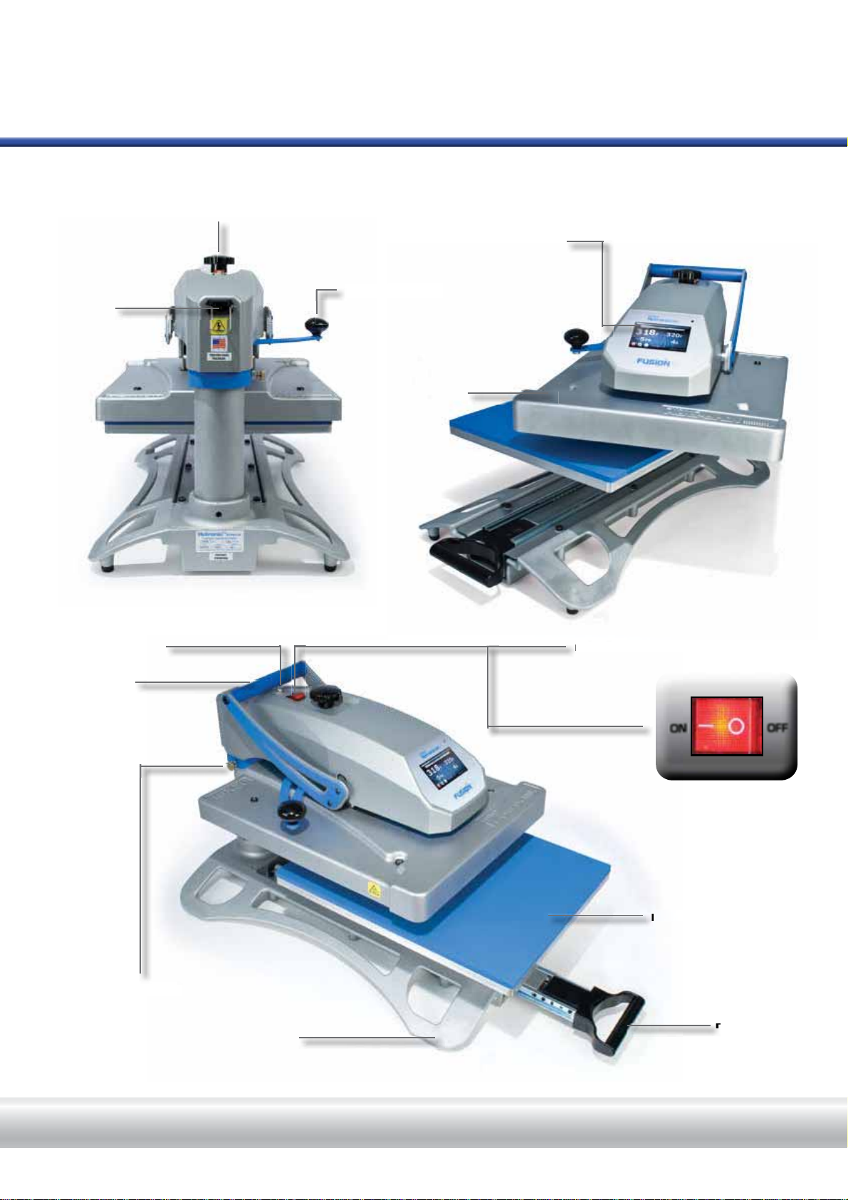
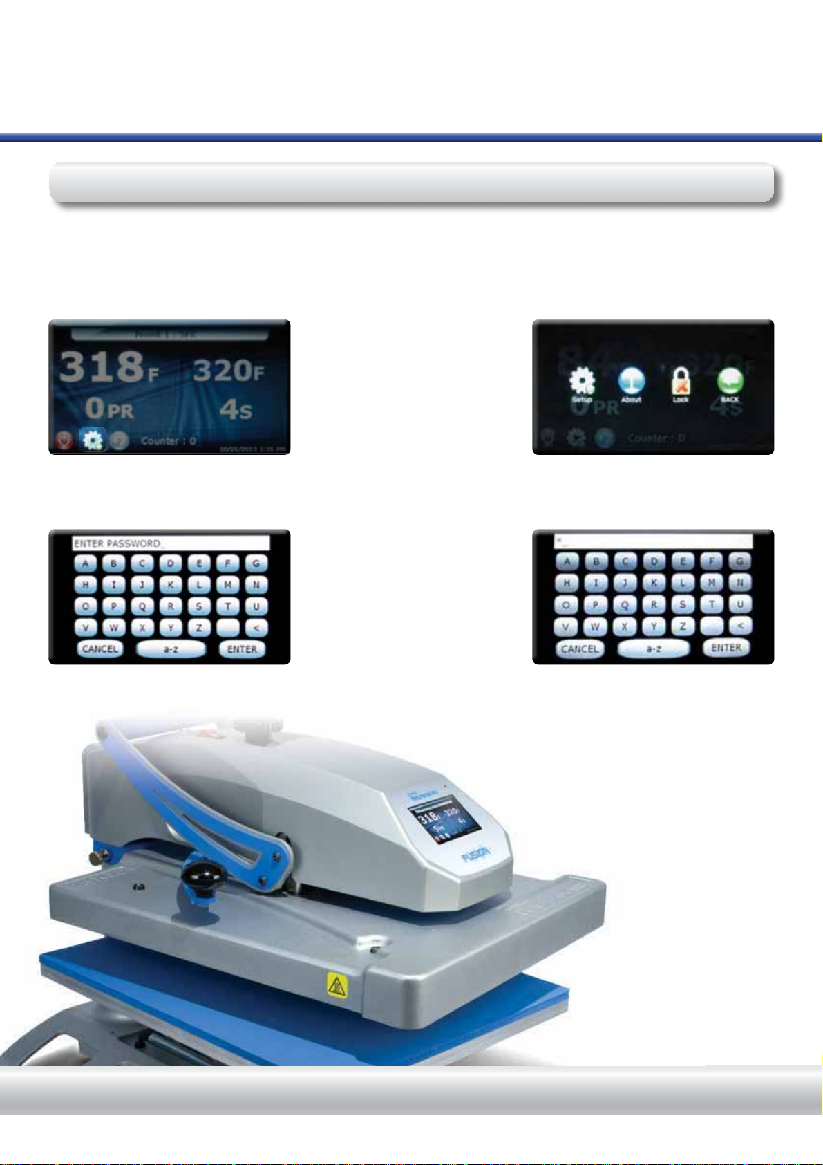
Stahl Hotronix DUAL Air Fusion User manual

O P E R AT O R’ S M A N U A L

S E R V I C E H O T L I N E : 8 0 0 . 7 2 7 . 8 5 2 0
1.
2.
3.
4.
5.
6.
7.
8.
9.
10.
11.
When using your heat press,
basic precautions should always be followed,
including the following:
Safety Instructions
Product Warranty Registration
Log onto www.Hotronix.com/registration
You must provide the Hotronix®heat press
serial number and model information.
Read all instructions.
Use heat press only for its intended use.
To reduce the risk of electric shock, do not immerse the heat press in water or other liquids.
Never pull cord to disconnect from outlet, instead grasp plug and pull to disconnect.
Do not allow cord to touch hot surfaces, allow heat press to cool completely before storing.
Do not operate heat press with a damaged cord or if the equipment has been dropped or damaged.
To reduce the risk of electric shock, do not disassemble or attempt to repair the heat press. Take it
WRDTXDOL¿HGVHUYLFHSHUVRQIRUH[DPLQDWLRQDQGUHSDLU,QFRUUHFWDVVHPEO\RUUHSDLUFRXOG
LQFUHDVHWKHULVNRI¿UHHOHFWULFVKRFNRULQMXU\WRSHUVRQVZKHQWKHHTXLSPHQWLVXVHG
This appliance is not intended for use by persons (including children) with reduced physical, sensory
or mental capabilities, or lack of experience and knowledge, unless they have been given supervision
or instruction concerning use of the appliance by a person responsible for their safety.
Close supervision is necessary for any heat press being used by or near children. Do not leave
equipment unattended while connected.
Burns can occur when touching hot metal parts.
To reduce the likelihood of circuit overload, do not operate other high voltage equipment on the same
circuit.
If an extension cord is necessary, then a 20 amperage rated cord should be used. Cords rated for
less amperage may overheat. Care should be taken to arrange the cord so that it cannot be pulled
or tripped over.

HOTRONIX®FUSION™
3
H O T R O N I X . C O M
Safety Instructions
Machine View
Touch Screen Guide
Operating Instructions
Connecting the System
Start Up/Shut Down
Print Screen
Passwords
Setup Menu
Presets Setup
Date & Time Setup
Display Setup
Auto On & Off Setup
Manager Level
Passwords Setup
Language Setup
System Setup
Prepare to Print
Replacing Parts
Electrical Schematic
Contact
2
4
5
6-19
6
7
8-9
10
11-18
11-12
13
14
15
16-18
16
17
18
19
20-21
22
23
Table of Contents

HOTRONIX®FUSION™
ON OFF
4S E R V I C E H O T L I N E : 8 0 0 . 7 2 7 . 8 5 2 0
Touch Screen
Lift Handle
Over-the-Center
Pressure Adjustment Knob
Machine View
Power ON/OFF Switch
Circuit Breaker
IEC Inlet
Swing Lock
Heat Platen
Swing Handle
Pull Handle
Lower Platen
Base
S
L
P
L
P

HOTRONIX®FUSION™
5
Fig.1
Fig.2
Fig.3
Fig.4
Fig.5
H O T R O N I X . C O M
Touch Screen Guide
Navigation
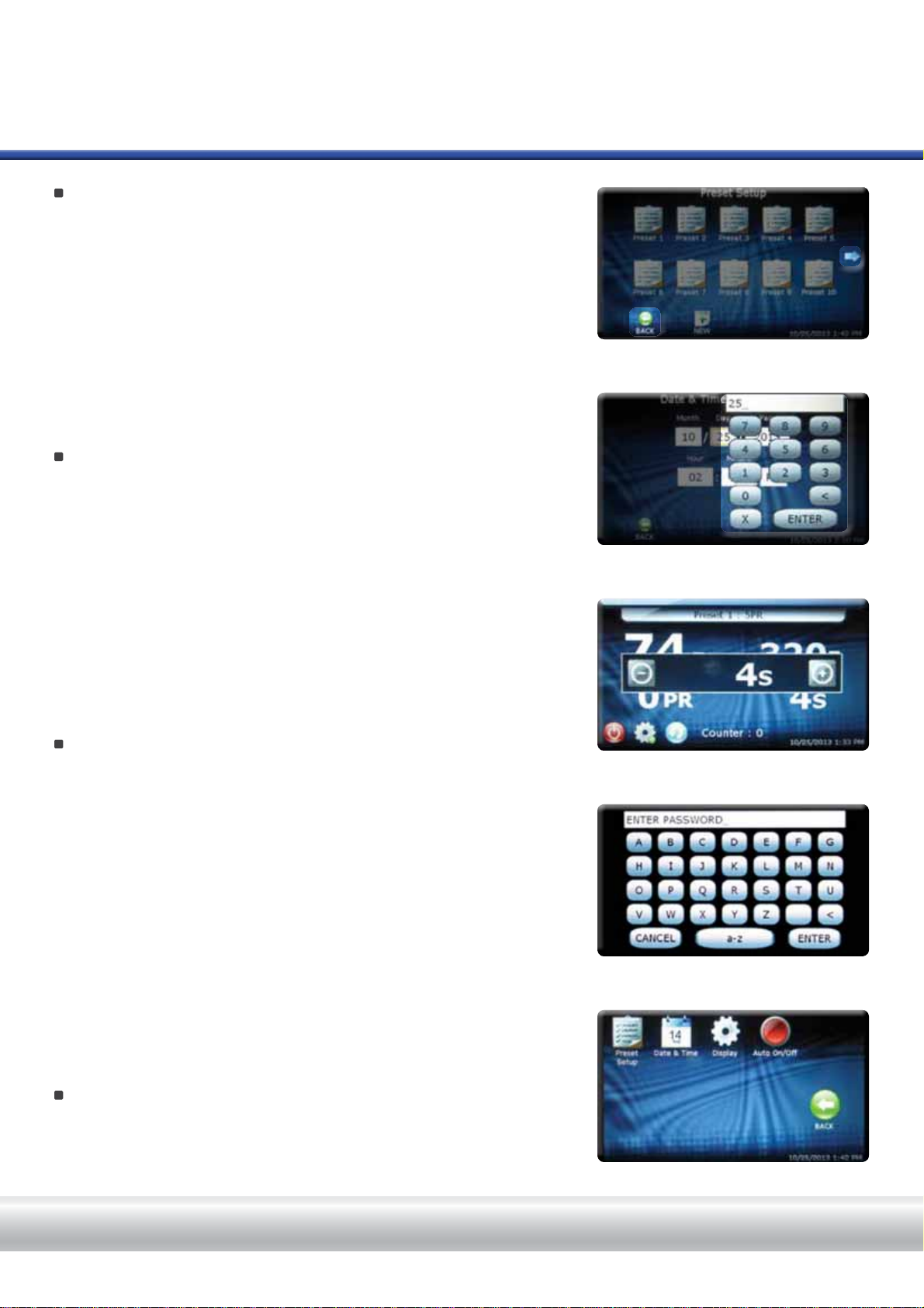
Most screens have a Cancel or Back button to close the current screen
without saving any changes and will return the user to the previous screen.
(Fig.1)
Some screens may present a list of items. When the list of items is larger
than can be displayed on a single screen a left and/or right arrow
appears on the left or right side of the screen. Auser can scroll through the
list by making a sweeping gesture across the screen, either left and/or right,
as indicated by the arrows. The user must be touching the screen for the
gesture to be detected. Very fast and very slow gestures may not be
recognized. (Fig.1)
Editing
(GLWDEOH¿HOGVPD\EHGLVSOD\HGLQDQ(GLW%R[$Q(GLW%R[W\SLFDOO\
RYHUOD\VWKHVFUHHQDQGSUHVHQWV¿HOGVDQGRUFRQWUROVEdit Boxes
typically do not have a Back or Cancel button. The Edit Box can be closed
by touching the screen anywhere outside the Edit Box, or by pressing the
(“X”) button. A Save or Enter button maybe displayed in an Edit Box.
Closing the Edit Box without pressing the Enter button will result in the
loss of your changes. (Fig.2)
Keyboard / Keypad Display
The Keyboard/Keypad display is used for data entry purposes. The
Keyboard/Keypad can be used to enter text or numeric data when required.
The Keyboard/Keypad provides function keys for Cancel, Enter and
Backspace/Clear (“<”) keys. Also, a mode key located between the Cancel
and Enter keys may be present. The mode key allows the user to switch
between upper and lower case letters and numeric and other characters
that may be entered using the Keyboard/Keypad. (Fig.4)
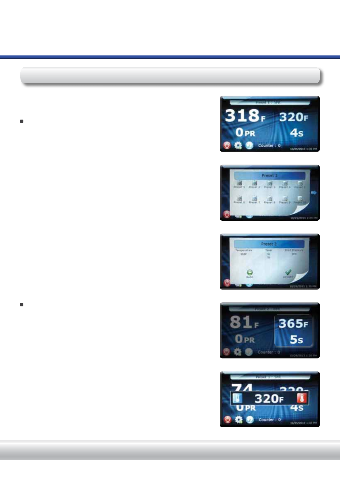
Typically, the current value is displayed in the Keyboard/Keypad value
display at the top of the screen. Use the Keyboard/Keypad to change the
current value. Use the Enter key to accept the change or the Cancel key to
exit without accepting the change to the current value. (Fig.4)
The Keyboard/Keypad display is also used for password entry. Password
characters will be displayed with “*” in place of the password value.
,QDGGLWLRQWRHGLWDEOH¿HOGVFHUWDLQLFRQVPD\EHSURYLGHGWRLQFUHDVHRU
decrease values. These icons (in most cases) can be held down to
automatically increase or decrease values. (Fig.3)
Menu Selection
The available Menu Screens are displayed as icon images on the screen.
Touch and release the icon to open the desired Menu Screen. (Fig.5)

HOTRONIX®FUSION™
HOTRONIX® FUSION™
1.
6
1.1
1.2
S E R V I C E H O T L I N E : 8 0 0 . 7 2 7 . 8 5 2 0
Connect the power cord into the IEC inlet located in the back of the Press.
(1.1)
Lower and lock the U-clip to secure the plug. (1.2)
Connect the opposite end of the cord into a properly grounded
HOHFWULFDORXWOHWZLWKDVXI¿FLHQWDPSHUDJHUDWLQJ
To avoid burns, do not touch the heated platen during use.
Keep hands clear of the upper platen of the press during platen
ORFNGRZQDVWKHSUHVVXUHPD\FDXVHLQMXU\
Press should be placed on a sturdy, suitable stand at least
Ǝ/[Ǝ:[Ǝ+
Work area must be kept clean, tidy and free of obstructions.
Power supply cord must be disconnected before
cleaning or servicing press.
The Hotronix®Fusion™Operating Instructions are designed with the user in mind. Carefully read and follow
the step-by-step instructions for best results.
Connecting the System
Operating Instructions
CAUTION Failure to follow these instructions will cause:
1. Erratic controller functions. 2. Inaccurate displays and slow heat-up. 3. The circuit breaker to disengage.
Note: If the supply cord is damaged, it must be replaced by the manufacturer, its service agent or a similarly
TXDOL¿HGSHUVRQLQRUGHUWRDYRLGKD]DUG8VH6-7W\SHUDWHG9IRUUHSODFHPHQW
Voltage
120 Volt - The Hotronix® Fusion™
requires a full 20 amp grounded
circuit for 120 volt operation.
220 Volt - The Hotronix® Fusion™
requires a full 10 amp grounded
circuit for 220 volt operation.
Extension Cords
If used, extension cords should be as short as possible and not less
than 12 gauge. Heavy-duty cords are recommended.
Circuits
Circuits that have less than 15 amps or that have other high demand
equipment or appliances (especially more than one heat seal machine)
plugged in, should not be used.

HOTRONIX®FUSION™
2.
7
2.22.1
H O T R O N I X . C O M
To start up your Fusion™Press:
Start Up / Shut Down
2.3 2.4
2.62.5
To turn your Fusion Press off, press and release the “Shut Down” button on the operation screen. (2.3)
Note: When the heat platen is
above 100°F (38°C), the current
platen temperature is displayed
on an orange background as a
warning, indicating that the platen
is still hot. (2.4)
Note: The Hotronix®Fusion is equipped with an Auto Sleep Mode. When the machine is not in use for a period of four
hours, it will enter an energy-saving sleep mode. To restore to normal operating mode, press the start button located
on the touch screen and allow the heat press to return to the target temperature.
During this time, the Shutdown operation can be exited by simply pressing the start button displayed on the touch
screen (2.4). The system will exit the Shutdown screen and return to the Main Menu.
Press and Hold the Shut Down
button until this screen appears.
(2.6)
Flip the main Power Switch at
the top of the press to the off
position.
Once the platen has cooled below 100° F (38° C), a screen saver will display, showing the Stahls Hotronix®logo,
START, and Shut Down buttons. (2.5)
Flip the Power switch to the On
position. (The power switch is
located on the top of the control
housing). (2.1) During the startup,
a splash screen is shown for
approximately 3 seconds. This
screen displays the Hotronix®
logo and current software version
information. (2.2)

HOTRONIX®FUSION™
8
3.1
3.2
3.5
3.4
3.3
Print Screen
Target Settings
Your target Temperature and Time settings are displayed as shown. (3.4)
These settings may be overridden.
To change your Temperature Settings, press the Target Temperature
display located on the right side of the print screen. A pop-up menu will be
displayed. Press the red or blue temperature icons to increase or
decrease the temperature (press and hold to change values faster). (3.5)
Note: The temperature can be set from a range of 32°F (0°C) to
430° F (221°C).
7KH3ULQW6FUHHQLVWKH¿UVWVFUHHQGLVSOD\HGDIWHUWKHVSODVKVFUHHQDQG
start up has completed. This screen provides all the printing functions.
Presets
Saved Presets are displayed at the top of the Print Screen. These are
pre-programmed heat application settings that allow you to quickly and
DFFXUDWHO\FKDQJH\RXUSULQWVHWWLQJVIRUVSHFL¿FPDWHULDOV7KHH[DPSOH
VKRZQLVDSUHVHWQDPHG³3UHVHW´ZLWKD¿UVWWLPHURIVHFRQGVD
target temperature of 320°F, and a platen pressure of 5. (3.1)
To select a new application setting, press the preset bar at the top of the
Print Screen. (3.1)
A pop up menu with all of the optional presets will be displayed. (3.2)
Note: if there are no Presets pre-programmed on your system, the
Preset menu will be blank.To edit, delete or create new presets, see
‘Preset Setup” on pages 11 and 12.
The system will automatically return you to the Print Screen showing your
new preset settings. (3.4)
Note: <RXFDQ³2YHUULGH´\RXUFXUUHQWKHDWDSSOLFDWLRQVHWWLQJVWR¿WDQ\
material desired. See “Target Settings” below.
Note: when changing a Target Setting, the Preset display name at the top
of the screen will change to “Override” to indicate the Preset has been
manually changed.
Press your desired preset and select the “ACCEPT” icon to continue. (3.3)
3.
S E R V I C E H O T L I N E : 8 0 0 . 7 2 7 . 8 5 2 0
Operating Instructions

HOTRONIX®FUSION™
9
3.6
3.8
3.7
3.9
Print Screen Cont.
Actual Readings
The Actual Temperature and Pressure readings are displayed on
the left side of the Print screen. These are the current heat press
readings. (3.7)
Note: The actual platen pressure will only be displayed when the
lift handle is locked down into the print position.
Target Settings Cont.
To change your Time Settings, press the Target Timer display located
on the right side of your print screen. A pop-up menu will be displayed.
Press the minus or plus icons to decrease or increase the time
(Press and hold to change values faster). (3.6)
Note: The time can be set from a range of 1-999 seconds.
Job Counter
7KH-RE&RXQWHUFRXQWVWKHWRWDOQXPEHURIFRPSOHWHSULQWF\FOHV
performed using the current Preset or Override settings. Exiting the
3ULQW6FUHHQRUFKDQJLQJWKH3UHVHWZLOOUHVHWWKH-RE&RXQWHUWR
&KDQJLQJDQ2YHUULGHVHWWLQJGRHVQRWUHVHWWKH-RE&RXQWHUWR
(3.8)
Setup button
The Setup menu allows you to edit and create Presets, program the
Date and Time, change your display units (F°/C°), set your Auto On/Off
functions and more. A password is required to enter the Setup menu.
The system supports two levels of passwords: “User” and “Manager”.
Features of the Setup menu are limited by the password level entered.
(3.9)
Note: See “Passwords”on page 10.
Power Button
Use the Power Button to perform system shutdowns. (3.9)
Note: See “Start up / Shut Down”on page 7.
Refresh Button
When using a Preset with multiple timer settings programmed, press
DQGKROGWKHUHIUHVKEXWWRQWRUHYHUWEDFNWRWKH¿UVWWLPHUVHWWLQJ
when desired. (3.9)
H O T R O N I X . C O M

HOTRONIX®FUSION™
10 S E R V I C E H O T L I N E : 8 0 0 . 7 2 7 . 8 5 2 0
4.44.3
4.24.1
$SDVVZRUGLVUHTXLUHGWRDFFHVVWKH6HWXS0HQXDQGFRQ¿JXUHFHUWDLQIXQFWLRQVRIWKH+RWURQL[®Fusion™. The
system supports two levels of passwords: “User” and “Manager”. The User Level password provides access to the
Preset Setup, Date & Time, Display, and Auto On/Off Setup screens. The Manager Level password provides
access to the Preset Setup, Date & Time, Display, Auto On/Off, Password, Language and System Setup screens.
In the Print Screen, press the Setup
icon. (4.1)
Then press the Setup icon again.
(4.2)
Note: we will continue under a
“User Level” password.
Press Enter when complete.
If an invalid password is entered,
simply repeat the previous step.
(4.4)
Note: You can Select the Cancel button to exit the Password Entry screen
and return to the previous screen at any time.
Now you will be automatically entered into the
Setup Menu where you will have access
to the Setup functions. (5.1)
Passwords
A keypad will be displayed. Enter the letter “U” for a user level password or “M” for a manager level password. (4.3)
4.
Operating Instructions

HOTRONIX®FUSION™
11
H O T R O N I X . C O M
5.2 5.3
5.6 5.7
5.55.4
Preset Setup
Press the NEW button on the
preset setup screen. (5.2)
First, give the Preset a name by
VHOHFWLQJWKH3UHVHW1DPH¿HOG
(5.3)
A keypad will be displayed. (5.4)
To create a new Preset:
If desired, you can also change
the Pressure and Temperature
units here by pressing the F or C
(Fahrenheight/Celsius). (5.5)
Type in the name of your new
Preset and Press ENTER when
¿QLVKHG
Repeat the same process for your
new Preset Timer, Pressure, and
7HPSHUDWXUH¿HOGV
Press the SAVE button when
¿QLVKHG
Note: if you receive an error message after saving, select the Error message. (5.6)
A Preset Error menu will display, informing you of any changes needed. (5.7)
Press the yellow Error icon again to the close the Error menu and make any necessary corrections.
3UHVVWKH6$9(EXWWRQDJDLQZKHQ¿QLVKHG
Setup Menu
After your password is entered in the setup menu, press the Preset Setup
icon. (5.1). This option will allow you to edit, delete, and create new
Presets. A preset can have:
• 1 Preset Name
• 1-4 Timer values each with a range of 1-999 seconds
• 1 Platen Pressure settings with a range of 0-9
Note: A “0” Pressure readout would indicate no pressure
at all and “9” would indicate very heavy pressure.
• 1 Temperature value with a range of 32°F - 430°F (0°C- 221°C)
5.
5.1

HOTRONIX®FUSION™
12 S E R V I C E H O T L I N E : 8 0 0 . 7 2 7 . 8 5 2 0
5.14
5.12
5.13
5.115.10
Preset Setup Cont.
Press the DELETE button. (5.13)
A pop up menu will appear. Press
ACCEPT to continue or CANCEL
to return to the Preset Setup page.
(5.14)
To Delete a Preset: In the Preset Setup menu, Select the name of the Preset you wish to delete. (5.12)
To edit an existing Preset:
In the Preset Setup menu, press the name of the Preset you wish to
change. (5.12)
6HOHFWWKHGHVLUHG¿HOG3UHVHW1DPH7LPHU3UHVVXUHRU7HPSHUDWXUH
that you wish to edit. A keypad will be displayed. Use the left arrow (<) to
override the current name or value, then key in your new entry desired.
3UHVV(17(5ZKHQ¿QLVKHGRU;WRFDQFHO
Note: If a blue arrow appears on your screen, this indicates there are more
presets hidden from view. 6OLGH\RXU¿QJHUDFURVVWKHVFUHHQWRZDUGVWKH
arrow to view the rest of your Presets.
Locate and select your New Preset.
(5.10)
Press ACCEPT. (5.11)
The Print Screen will now display
your new settings.
To Create a New Preset (Continued):
Operating Instructions
5.8 5.9
Note: A DELETE button will
appear after saving if you do not
wish to save. (5.8)
Press the BACK button until you
return to the Print Screen.
The message “Saving Settings!
Please wait...” will appear.
Press the Presets bar at the top of the Print Screen to select your New Preset. (5.9)

HOTRONIX®FUSION™
13
H O T R O N I X . C O M
Setup Menu
6.3 6.4
6.1 6.2
Date & Time Setup
6.
Change the numeric value using the
displayed Keypad, then press Enter.
(6.3)
Repeat the same process to set the
Day, Year, Hour and Minute.
Select the AM/PM button to toggle
between the AM/PM settings.
The Date and Time Setup feature allows you to program the Month, Day, Year, Hour and Minute (displayed in the
lower right corner of the Print Screen).
Press the SAVE button to save the new Date and Time
settings. (6.4)
Note: It may take a few seconds for the Date and
Time display to update on your screen.
Select the BACK button to return to the
Setup menu. (6.4)
To set the Date and Time, press the
Date & Time button in the Setup
screen. (6.1)
3UHVVWKH³0RQWK´¿HOG

HOTRONIX®FUSION™
14 S E R V I C E H O T L I N E : 8 0 0 . 7 2 7 . 8 5 2 0
7.3 7.4
Display Setup
Press the SAVE button to save your
changes. (7.3)
Select the BACK button to return to
the Setup menu. (7.4)
Operating Instructions
7.1 7.2
7. The Display Setup allows you to change your Temperature units (Fahrenheit/Celcius)
To change your display units, press
the Display button in the Setup
screen. (7.1)
3UHVVWKH7HPSHUDWXUH¿HOG)RU&
to toggle between Fahrenheit and
Celsius. (7.2)

HOTRONIX®FUSION™
15
H O T R O N I X . C O M
8.1 8.2
8.3 8.4
8.5 8.6
8.7 8.8
Auto On and Off Setup
8. 7KHV\VWHPFDQWXUQ2QRU2IIDXWRPDWLFDOO\ZKHQFRQ¿JXUHG7KH$XWR2QDQG2IIIHDWXUHLVFRQ¿JXUHGIRUHDFKGD\
of the week.
In the Setup Menu, Select the Auto
On/Off Button. (8.1)
7RFRQ¿JXUHDQ$XWR2Q2IIVHWWLQJ
select the day of the week to be
FRQ¿JXUHG(8.2)
Use the Enable/Disable button to
enable On/Off settings for the
selected day of the week. (8.3)
Note: Each day that you want the
system to automatically turn On/Off,
must be Enabled.
Using the displayed Keyboard/
Keypad, enter the numeric time
values and press ENTER. (8.5)
Use the AM/PM designator button
to toggle between the AM or PM
settings. (8.6)
Press the BACK button to return
to the Automatic On and Off Setup
screen. (8.7)
Note: You will see a green check
mark for any day you have your
Auto On/Off Enabled. (8.8)
:KHQHQDEOHGVHWWKHWLPHRIGD\IRU$XWR2QDQG2IIHYHQWVE\VHOHFWLQJWKH+RXUDQG0LQXWH¿HOGV
Select the SAVE button to save the settings. (8.6)
Note: Selecting another day of the week or exiting the Auto On and Off Setup screen without saving will result in loss
of changes.
Setup Menu

HOTRONIX®FUSION™
16 S E R V I C E H O T L I N E : 8 0 0 . 7 2 7 . 8 5 2 0
Operating Instructions
9.1 9.2
9.
9.3 9.4
Passwords Setup (Manager Level Only)
When logged in at a “Manager Level”, Passwords may be changed In the Setup menu. This will allow you to control
who can access additional features in the Setup menu such as Passwords, Language and System Setup.
Type in your new Password and
SUHVV(17(5ZKHQ¿QLVKHG
Note: Do not forget your new
Password(s). It will be required for
future logins.
Save any changes prior to exiting
the Password Setup screen to
prevent losing your changes. (9.4)
Press the Passwords setup icon
in the Setup menu. (9.1)
Select the Password level (User
or Manager) to be edited. (9.2)
A Keyboard / Keypad will be
displayed. (9.3)
Note: To continue at a “Manager Level”, select the letter “M” in the Setup menu and press enter
(see “Passwords” on page 10).
You can also access the “Lock” function when logged in at a Manager Level. This feature will prevent a user from
changing any print settings and functions of the print screen when heat applying.
9.69.5
To Lock the print settings, Press the
Lock icon in the Setup menu. (9.5)
Type in your Manager Level
password and press ENTER when
¿QLVKHG
Note: The “Unlock” icon will now be
displayed in the setup screen if you
wish to Unlock the print settings.
(9.7)
Press the BACK button in the Setup
menu. (9.7)
The print screen will now display
the Lock icon indicating the heat
application settings will no longer
be editable. (9.6) 9.69.7

HOTRONIX®FUSION™
17
H O T R O N I X . C O M
Setup Menu
10.1 10.2
10.3 10.4
10. When logged in at a “Manager Level”, the display Language may be changed in the Setup menu. Choose from eight
ODQJXDJHV(QJOLVK'HXWVFK(VSDQRO)UDQFDLV,WDOLDQR-DSDQHVH3\FFNRDQG&KLQHVH
In the Setup Menu, Select the
Language Button. (10.1)
Press the icon of your Desired
Language. (10.2)
Note: The selected icon will appear
larger than unselected icons.
Once the desired language is
selected, press the Save button.
(10.3)
This example shows the Language “Espanol” being selected. (10.3)
Language Setup (Manager Level Only)
Your Fusion™ will automatically restart and return you to the Print Screen using the new Language display settings.
(10.4)

HOTRONIX®FUSION™
18
11.3
11.4
11.2
8VHWKHSOXVPLQXVEXWWRQVWRDGMXVWWKHIUHTXHQF\VHWWLQJRUVHOHFW
WKH¿HOGYDOXHWRGLVSOD\D.H\ERDUG.H\SDGIRUHGLWLQJWKHYDOXH
Note: The value can be set in the range of 1 - 10000 Hz.
After your new frequency value is entered, press the ENTER key. (11.4)
Key Touch Frequency
When the user touches a control on the screen an audible tone is
SURGXFHGDVDYHUL¿FDWLRQWKDWDFRQWUROZDVWRXFKHG7KHWRQHIUHTXHQF\
FDQEHFKDQJHGE\DGMXVWLQJWKH.H\7RXFK)UHTXHQF\V\VWHPVHWWLQJ
(11.3)
Press the SAVE button to save any changes, followed by the BACK
button. (11.5)
Press the BACK button again in the Setup menu to return to the Print
Screen.
Power Save Status
With the Power Save Status turned on, the system will automatically shut
down after 4 hours of innactivity to save power. The Power Save Feature
can be turned On or Off by selecting the On/Off button. (11.2)
System Setup (Manager Level Only)
11.5
11.1
11. When logged in at the “Manager Level”, system functions such as
Internal Temperature, Fan Status, Power Save Status, and Key Touch
)UHTXHQF\FDQEHWXUQHGRQRIIRUDGMXVWHGLQWKH6HWXSPHQX
Press the System icon in the Setup menu. (11.1)
Internal Temperature
The current internal temperature reading of the system is displayed. (11.2)
Operating Instructions

HOTRONIX®FUSION™
19
12.1
Prepare to Print
When the desired settings are reached you may begin to Print / Press.
To begin Printing/Pressing, start by verifying that you have the proper settings selected in the Print Screen: (12.1)
Do you have the correct preset selected?
Note:<RXPD\DOVRPDQXDOO\DGMXVW\RXUGHVLUHG7LPH7HPSHUDWXUH
and Pressure settings (refer to Target Settings on pg 8-9).
Also, Be sure your Actual Temperature Setting has reached the
Target Temperature.
12.
12.2
12.3
The Timer display on your Print Screen will automatically initiate
a count down. It will visually and audibly signal you when to lift
the platen off the garment. Immediately lift the platen to the
UP position.
When using the “Swing” feature, swing the heat platen out and
position the garment and application. (12.2)
Swing the heat platen or pull the lower platen away and proceed according to your application’s instructions.
Swing the heat platen or push the lower platen back into position.
Lower the heat platen into the press position. (12.4)
Your equipment has automatically reset and you may continue to Print / Press.
12.4
When using the “Draw” feature, pull out the lower platen and position
the garment and application. (12.3)

HOTRONIX®FUSION™
20 S E R V I C E H O T L I N E : 8 0 0 . 7 2 7 . 8 5 2 0
Replacement Parts List
Item #
1
2
3
4
5
6
7
8
9
10
11
12
13
14
15
16
17
18
19
20
21
22
23
24
25
26
27
28
29
30
31
32
33
34
35
36
37
38
39
40
41
42
43
44
45
46
47
48
49
50
51
52
53
54
55
Part #
Kit 3-6942
1-2199
1-2255
3-1011-245
1-2203
2-1006-93
1-2206
1-2204
2-1664
2-1006-21
2-1006-1
Kit 3-6943
1-1019-1
1-2217
1-1010-2
1-1012
2-1006-92
1-2201
1-1018-1
1-1054
1-1013
1-2255
1-2194
Kit 3-6911
0175-12
1-2116
1-1024
1-1017-1
2-1006-20
3-1011-244
1-2207
1-1300
1-2208
3-1335
1-1749
1-2164
1-2195
2-1006-65
3-1011-121
1-2182
1-2215
3-1336
2-1029
1-2136
2-1002
1-2189
1-1063
3-1011-217
1-2266
1-2198
1-2197
1-2087
1-1331
1-1759
2-1013-1
Qty.
1
4
1
2
1
1
2
1
1
1
1
1
1
1
1
1
1
1
2
1
1
1
1
1
1
1
2
2
2
3
2
2
2
1
1
1
6
6
6
1
1
1
1
1
1
1
4
4
1
1
1
1
1
1
1
Part Name
Base Assembly
Rubber Foot
Right Upper Link
/RZ3UR¿OH6+&6
Stop Collar
Hex Nut
Hand Retractable Plunger
Steel Pin
Upper Casting
Washer
Castle Nut
$GMXVWPHQW&DVWLQJ
E-Clip
Steel Shim
$GMXVWPHQW6SLQGOH
$GMXVWPHQW.QRE
Spherical Washer
Ball Plunger
Roll Pin
Swing Knob
Lift Rod Bushing
Left Upper Link
Guide Tube
Undercarriage
Handle Spacer
Foam Grip
Lift Link
Clevis Pin
Nylon Lock Nut
6FUHZ&DS%XW+G[ôƎ
Inner Lift Arm (Thick)
Bearing
Outer Lift Arm (Thin)
C-Frame
Slide Rail
Draw Tray
Compression Spring
Nylon Washer
Shoulder Bolt
Draw Handle
Quick Change Pin
Adaptor Plate
Lower Platen
6LOLFRQH3DGƎ[Ǝ%OXH
+HDW3ODWHQƎ[Ǝ
Heater Cover
Finish Washer
Cover Screw
Touch Screen Controller
Control Housing Overlay
Control Housing
Power Switch
Breaker
IEC Inlet
Power Cord
Other manuals for Hotronix DUAL Air Fusion
4
Table of contents
Other Stahl Power Tools manuals