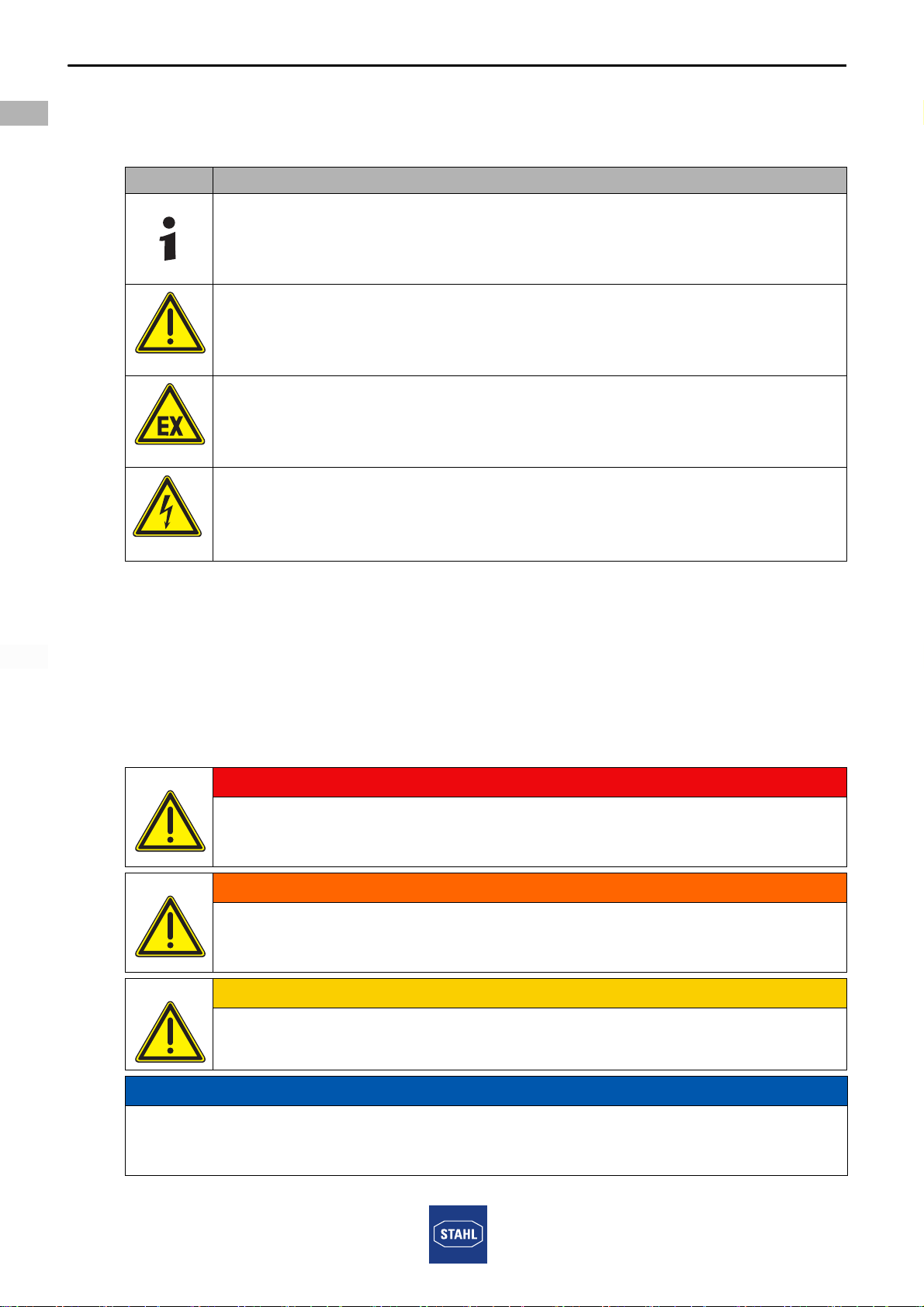
Safety notes
6916260330020
2018-03-08·HB00·III·en·02
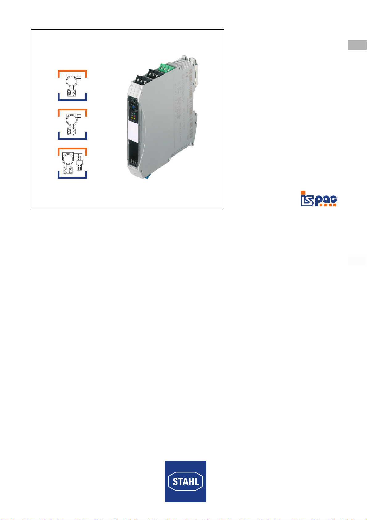
Transmitter Supply Unit with Limit Values
Series 9162
EN
EN
EN
EN
EN
EN
EN
EN
EN
EN
EN
EN
EN
EN
EN
EN
EN
EN
EN
EN
EN
EN
EN
EN
EN
For mounting and installation
• Observe national installation regulations (e.g. IEC/EN 60079-14).
• Observe national safety and accident prevention regulations.
• During installation and operation, observe the information (characteristic values
and rated operating conditions) on the rating, data and information plates located
on the device.
• Before installation, make sure that the device is not damaged.
• Electric circuits with type of protection "Ex i" operated with circuits with other types of
protection can no longer be operated as circuits with type of protection "Ex i" after that.
• When used in Zones 2 and 22, the intrinsically safe devices of Zones 1, 0, 21
and 20 can be connected to the intrinsically safe signal circuits.
• The safety characteristic values of the connected field devices must correspond
to the specifications in the data sheet or in the EC Type Examination Certificate.
• Interconnecting several devices in a single intrinsically safe circuit can result in
different safety characteristic values. This may impair intrinsic safety!
• Before carrying out work on the device, the body's own voltage must be discharged
on earthed metal parts or an ESD wrist strap must be put on.
• Connect the device only to equipment which does not carry voltages higher than
253 V AC (50 Hz).
• Ensure that there is a distance of at least 50 mm (tight string length) between
connecting units of intrinsically safe and non-intrinsically safe circuits when
setting up field circuits.
• The power supply of 24 V DC must be able to bridge brief interruptions of 20 ms
in order to ensure power failure bridging according to IEC/EN 61326-3-2 and NE 21.
Maintenance, repair, commissioning
• Before commissioning, make sure that the device is not damaged.
• Work on the device, such as installation, maintenance, overhaul, repair,
may only be carried out by appropriately authorised and trained personnel.
• Perform only maintenance work or repair described in this manual.
• For SIL applications observe the safety manual and FMEDA reports.
• Make sure to use suitable cables and cable glands for temperatures below -20 °C.
• The configuration interface of the device can only be connected to a non-sparking
equipment with low power rating (according to IEC/EN 60079/15, chapter 13)
or for maintenance purposes in compliance with IEC/EN 60079-17, chapter 4.6.
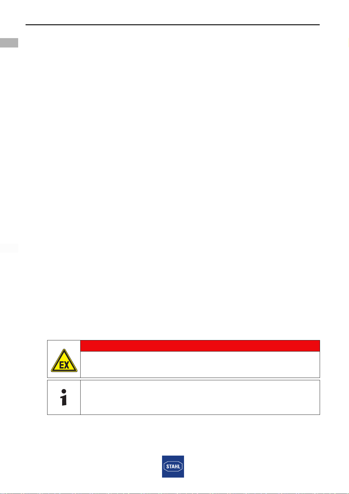
3.3 Modifications and alterations
DANGER
Explosion hazard due to modifications and alterations to the device!
Non-compliance results in severe or fatal injuries.
• Do not modify or alter the device.
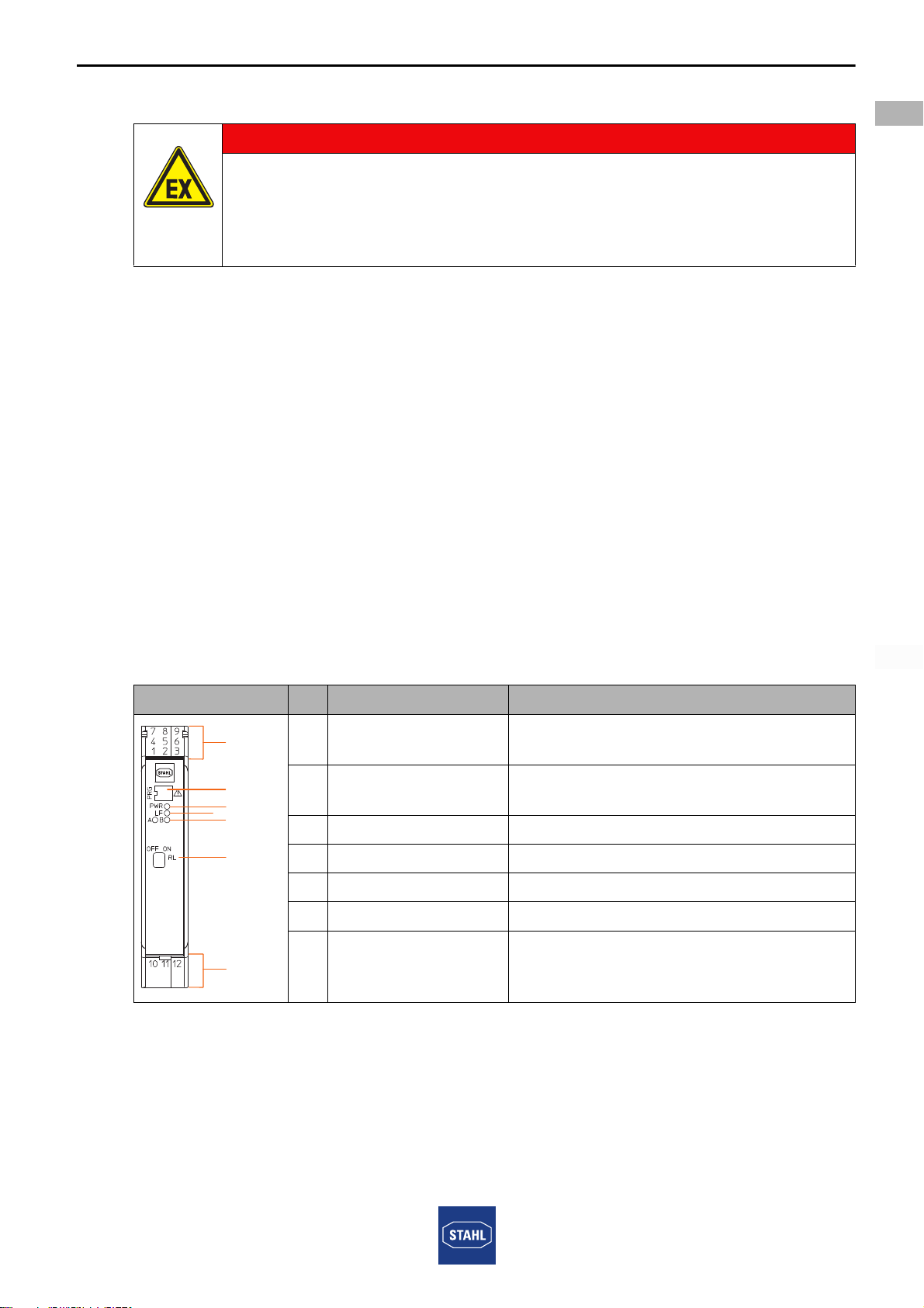
No liability or warranty for damage resulting from modifications and
alterations.