manuals.online logo
Brands
  1. Home
  2. •
  3. Brands
  4. •
  5. STAMOS
  6. •
  7. Welding System
  8. •
  9. STAMOS SWS03 User manual

STAMOS SWS03 User manual

SWS03
SWS04
SWS02N
USER MANUAL | INSTRUKCJA OBSŁUGI | MANUEL D‘UTILISATION | ISTRUZIONI D`USO | MANUAL DE INSTRUCCIONES | NÁVOD K POUŽITÍ
BEDIENUNGSANLEITUNG
expondo.de
2 3
DE
EN
PL
CZ
FR
IT
ES
3
4
5
6
7
8
9
DE
INHALT | CONTENT | CONTENU | CONTENIDO | TREŚĆ | CONTENUTO | OBSAH
NAZWA PRODUKTU EKRAN SPAWALNICZY
PRODUKTNAME SCHWEIßVORHANG / SCHWEIßVORHANG MIT GESTELL / SCHWEIßSCHUTZWAND
PRODUCT NAME WELDING CURTAIN/WELDING SCREEN
NOM DU PRODUIT RIDEAU DE SOUDURE
NOME DEL PRODOTTO PARETE DI PROTEZIONE PER SALDATURA
NOMBRE DEL PRODUCTO CORTINA DE PROTECCIÓN PARA SOLDADURA
NÁZEV VÝROBKU SVÁŘECÍ ZÁVĚS
MODEL PRODUKTU
SWS03
SWS04
SWS02N
MODELL
PRODUCT MODEL
MODÈLE
MODELLO
MODELO
MODEL VÝROBKU
IMPORTER
EXPONDO POLSKA SP. Z O.O. SP. K.
IMPORTEUR
IMPORTER
IMPORTATEUR
IMPORTATORE
IMPORTADOR
DOVOZCE
ADRES IMPORTERA
UL. NOWY KISIELIN-INNOWACYJNA 7, 66-002 ZIELONA GÓRA | POLAND, EU
ADRESSE VON IMPORTEUR
IMPORTER ADDRESS
ADRESSE DE L'IMPORTATEUR
INDIRIZZO DELL'IMPORTATORE
DIRECCIÓN DEL IMPORTADOR
ADRESA DOVOZCE
DE
BEDIENUNGSANLEITUNG
ANWENDUNGSGEBIET
Die Schweißerschutzwand ist eine individuelle
Schutzvorrichtung, die den Arbeitsbereich umschließen
und sichern soll. Es schützt Ihre Mitarbeiter vor Lichtbögen,
Funken und Splittern.
Für alle Schäden bei nicht zweckgemäßer Verwendung
haftet allein der Betreiber.
TECHNISCHE DETAILS
Setzen Sie die Schutzwand zusammen, indem Sie die
Elemente so anbringen, dass sie sich an den in der
Abbildung angegebenen Stellen benden.
1. Die mit den Nummern 1, 2, 9, 4 und 5
gekennzeichneten Elemente der Schutzwand sind
mit dem Riegel verbunden.
2. Die Element Nr. 3 dient zur Befestigung weiterer
Stellageteile. Sie werden auf Element 1 angebracht, das
zwischen den Schnappverschlüssen positioniert ist.
3. Element Nr. 5 und Element Nr. 6 werden mit einer
Flügelschraube befestigt.
4. Die Gewindestifte 7 (mit Bremse) und 8 (ohne Bremse)
werden in die Löcher in der Basis des Ständers (Nr. 6)
eingesetzt und mit der Mutter verschraubt.
5. Die Stellage ist jetzt einsatzbereit.
HINWEISE ZUR VERWENDUNG
• Die Schweißerschutzwand erfüllt die Anforderungen
der Norm EN ISO 25980.
• An dem Schirm benden sich um den gesamten
Umfang herum Önungen, die mithilfe der im Set
enthaltenen Kabelbinder zur Montage dienen.
• Die Stellage verfügt über Plastikräder, um die
Konstruktion problemlos auf glatter Oberäche
bewegen zu können. Zwei der Räder haben eine Bremse.
• Überprüfen Sie nach jedem Gebrauch, ob das
Produkt beschädigt ist.
• Verwenden Sie niemals ein defektes Produkt.
• Kunststoteile nicht mit Lösungsmitteln reinigen.
Benzin, Verdünnungsmittel, Benzol, Alkohol oder Öl
können die Kunststoteile beschädigen. Mit einem
weichen Tuch mit Wasser und Seife reinigen.
• Zum Reinigen der Stellage-Oberächen
ausschließlich nicht ätzende Substanzen verwenden.
• Sichern Sie das Produkt während des Transports
gegen versehentliche Beschädigung.
ZUSAMMENBAU DER STELLAGE
Rev. 28.10.2019 Rev. 28.10.2019
1
9 2
4
5
8
73
6
1
9
1
1
3
9
1
3
6
8 7
8 2 9 2 7 6
55
4 4
2 9 2
Produktname Schweiß-
vorhang
Schweiß-
vorhang
mit
Gestell
Schweiß-
schutz-
wand
Modell SWS03 SWS04 SWS02N
Schirmabmessun-
gen [mm]
2390x0,4x1750
Abmessungen des
Rahmens [mm]
-- 2390x1960
Schirmmaterial UV-beständiger, feuerfester
Kunststo; Kevlarfäden
Lichttransmission
basierend auf einer
Lichtquelle A>
0.0001 [%]
0,9 0,93
Spektrale Durchläs-
sigkeit für Wellen-
längen 210nm≤λ
≤313nm [%]
< 0,002
Spektrale Durchläs-
sigkeit für Wellen-
längen 313nm≤λ
≤400nm [%]
< 3
Gefahrenstufe
<1 (400nm≤λ
≤1400nm)
0,66 0,6
Lichtdurchlässigkeit
basierend auf der
Lichtquelle A nach
der Einwirkung von
UV-Licht [%]
0,66 0,63
Relative Änderung
der Lichtdurchläs-
sigkeit nach UV-
Bestrahlung [%]
11 29,6
Gefahrenstufe
<1 (400nm≤λ
≤1400nm) nach
Einwirkung von
UV-Strahlen
0,21 0,59
Material der Rah-
menkonstruktion
– – Stahlkonstruktion,
Kunststoräder
Schirmgewicht [kg] 2,4
Gewicht
der Stellage [kg]
-- 6,35
4 5
EN
USER MANUAL
AREAS OF APPLICATION
The welding screen is a personal protection equipment
item designed to separate and protect the working area.
It is used to protect workers from the welding arc light,
sparks and spatter.
The user is responsible for any damage resulting from
non-intended use of the device.
TECHNICAL DATA
Assemble the stand by connecting the individual elements
so that they are aligned according to the positions marked
on the diagram.
1. Connect stand elements marked with numbers 1, 2,
9, 4 and 5 using snap fasteners.
2. Use elements number 3 to connect to another
stand. Place them over element 1 between the snap
fasteners.
3. Use a wing bolt to attach element number 5 to
element number 6.
4. Place threaded wheel pins 7 (with brake) and 8
(without brake) in the stand base (element number
6) and tighten with nut.
5. The stand is ready for use.
USE GUIDELINES
• The welding screen is compliant with EN ISO 25980
standard.
• There are eyelets along the entire circumference of
the screen for attaching the screen using cable ties
included in the accessories.
• The stand is equipped with plastic wheels so that it
can be moved over at surfaces. There are brakes on
two of the wheels.
• Inspect for damage after each use.
• Do not use if the product is damaged.
• Do not wipe plastic parts with solvent. Solvents such
as gasoline, thinner, benzene, alcohol, ammonia and
oil may damage and crack plastic parts. Do not wipe
them with such solvents. Wipe plastic parts with
a soft cloth lightly dampened with soapy water.
• Clean stand surface using detergents free from
corrosive substances.
• Secure the product against accidental damage
during transport.
ASSEMBLING THE STAND
PL
INSTRUKCJA OBSŁUGI
OBSZAR ZASTOSOWANIA
Ekran spawalniczy jest środkiem ochrony indywidualnej
przeznaczonym do odgrodzenia i zabezpieczenia
przestrzeni roboczej. Służy do ochrony współpracowników
przed światłem łuku elektrycznego, iskrami oraz
odłamkami.
Odpowiedzialność za wszelkie szkody powstałe
w wyniku użytkowania niezgodnego z przeznaczeniem
ponosi użytkownik.
Nazwa produktu Ekran Spawalniczy
Model SWS03 SWS04 SWS02N
Wymiary ekranu [mm] 2390x0,4x1750
Wymiary stelażu [mm] -- 2390x1960
Materiał wykonania
ekranu
Odporny na promieniowanie
UV, ognioodporny plastik,
szwy z nici kewlarowych
Przepuszczalność
świetlna oparta na
źródle światła A>0.0001
[%]
0,9 0,93
Transmitancja
spektralna dla długości
fal 210nm≤λ≤313nm
[%]
< 0,002
Transmitancja
spektralna dla długości
fal 313nm≤λ≤400nm
[%]
< 3
Poziom zagrożenia <1
(400nm≤λ≤1400nm)
0,66 0,6
Przepuszczalność
świetlna oparta
na źródle światła
A po naświetlaniu
promieniami UV [%]
0,66 0,63
Względna zmiana
przepuszczalności
świetlnej po
naświetlaniu
promieniami UV [%]
11 29,6
Poziom zagrożenia <1
(400nm≤λ≤1400nm)
po naświetlaniu
promieniami UV
0,21 0,59
Materiał wykonania
stelażu
– – Stalowa
konstrukcja,
plastikowe kółka
Waga ekranu [kg] 2,4
Waga stelażu [kg] -- 6,35
DANE TECHNICZNE
Złożyć stelaż łącząc ze sobą poszczególne elementy tak, aby
znajdowały się w miejscach odpowiednio oznaczonych na rysunku.
1. Elementy stelaża oznaczone numerami 1, 2, 9, 4 i 5
łączy się na zatrzask.
2. Elementy nr 3 służą do dołączenia kolejnego
stelaża. Nakłada się je na element 1, umiejscawiając
pomiędzy zatrzaskami.
3. Element nr 5 z elementem nr 6 mocuje się śrubą
motylkową.
4. Gwintowane trzpienie kółek 7 (z hamulcem) i 8 (bez
hamulca) umieszcza się w otworach w podstawie
stojaka (el. Nr 6) oraz zakręca nakrętką.
5. Stelaż jest gotowy do użytku.
WSKAZÓWKI UŻYTKOWANIA
• Ekran spawalniczy spełnia wymagania normy EN ISO
25980.
• Na ekranie na całym obwodzie znajdują się oczka
służące do montażu ekranu za pomocą opasek
zaciskowych znajdujących się w akcesoriach.
• Stelaż posiada plastikowe kółka umożliwiające
bezproblemowe przesuwanie go po płaskiej
powierzchni. Dwa z kółek posiadają hamulec.
• Po każdym użyciu kontrolować, czy produkt nie uległ
uszkodzeniu.
• Nigdy nie używać uszkodzonego produktu.
• Nie należy wycierać elementów z tworzyw
sztucznych rozpuszczalnikami. Rozpuszczalniki
takie jak benzyna, rozcieńczalnik, benzen, alkohol,
amoniak czy olej mogą zniszczyć elementy z tworzyw
sztucznych. Elementy te czyścić przy użyciu miękkiej
ściereczki zwilżonej wodą z mydłem.
• Do czyszczenia powierzchni stelaża należy stosować
wyłącznie środki niezawierające substancji żrących.
• Na czas transportu zabezpieczać produkt przed
przypadkowymi uszkodzeniami.
SKŁADANIE STELAŻA
Rev. 28.10.2019 Rev. 28.10.2019
Product name Welding Curtain/
Welding Screen
Model SWS03 SWS04 SWS02N
Screen dimensions
[mm]
2390x0.4x1750
Stand dimensions [mm] -- 2390x1960
Used materials (screen) UV resistant, ame retardant
plastic, Kevlar thread seams
Light permeability
based on an A>0.0001
light source [%]
0.9 0.93
Spectral transfer
ratio for wave length
210nm≤λ≤313nm [%]
< 0.002
Spectral transfer
ratio for wave length
313nm≤λ≤400nm [%]
< 3
Hazard level <1
(400nm≤λ≤1400nm)
0.66 0.6
Light permeability
based on an A light
source after exposure
to UV rays [%]
0.66 0.63
Relative change in
light permeability after
exposure to UV rays [%]
11 29.6
Hazard level <1
(400nm≤λ≤1400nm)
after exposure to UV
rays
0.21 0.59
Used materials (stand) – – Steel frame, plastic
wheels
Screen weight [kg] 2.4
Stand weight [kg] -- 6.35
1
9 2
4
5
8
73
6
1
9
1
1
3
9
1
3
6
8 7
8 2 9 2 7 6
55
4 4
2 9 2
1
9 2
4
5
8
73
6
1
9
1
1
3
9
1
3
6
8 7
8 2 9 2 7 6
55
4 4
2 9 2
6 7
CZ
NÁVOD K OBSLUZE
OBLAST POUŽITÍ
Svářecí zástěna je osobním ochranným prostředkem
určeným pro oddělení a ohrazení pracovního prostoru.
Slouží k ochraně spolupracovníků proti výbojům
elektrického oblouku, jiskrám a střepinám.
Odpovědnost za veškeré škody vzniklé v důsledku
použití zařízení v rozporu s určením nese uživatel.
TECHNICKÉ ÚDAJE
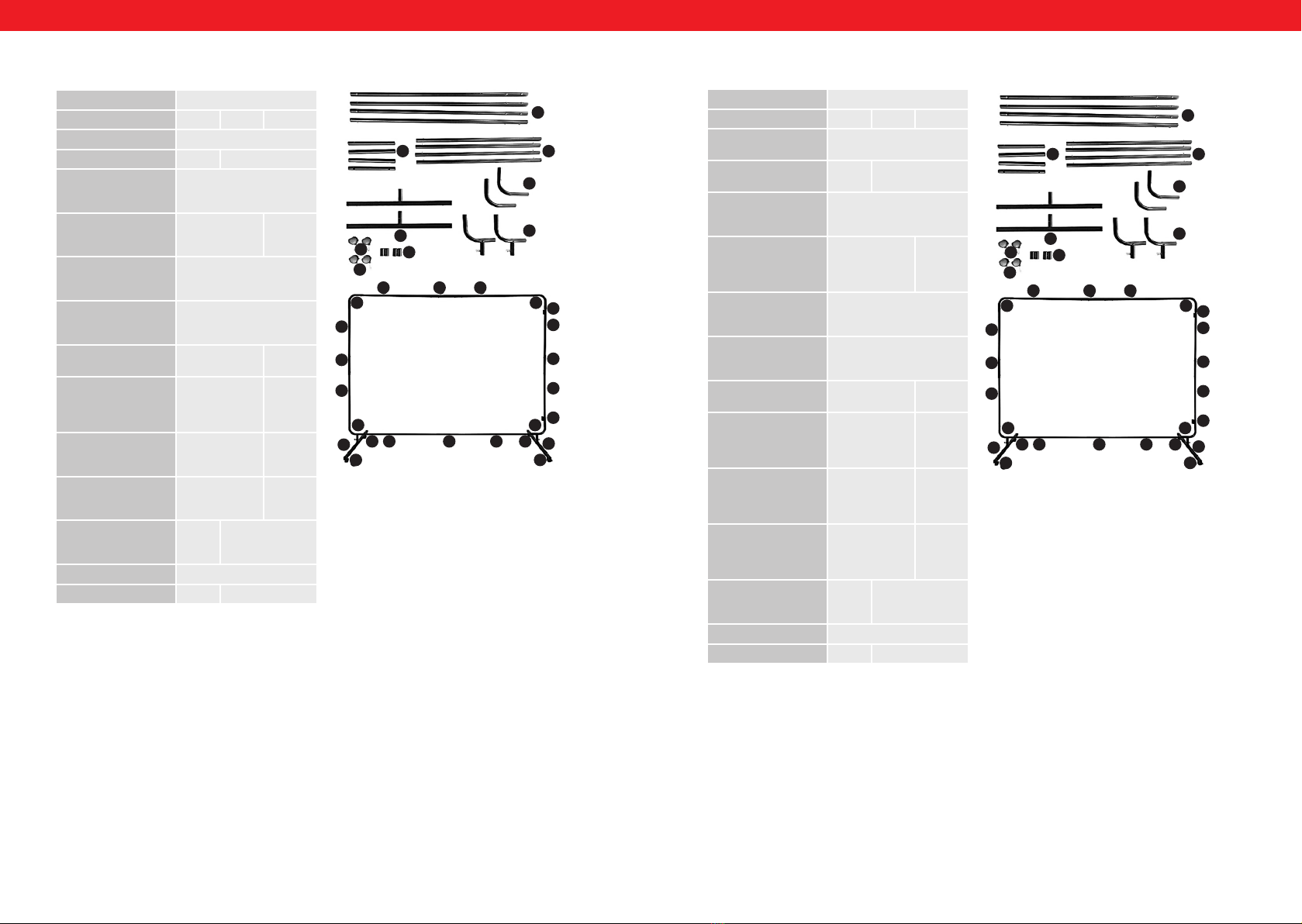
Rám poskládejte spojením jednotlivých dílů tak, aby se
nacházely na stejných místech jako na obrázku.
1. Díly rámu označené čísly 1, 2, 9, 4 i 5 spojte přezkami.
2. Díly 3 slouží pro připojení dalšího rámu. Nasazují se
na díl 1 umístěním mezi přezky.
3. Díl 5 se spojte s dílem č. 6 motýlkovým šroubem.
4. Závitové kolíky koleček 7 (s brzdou) a 8 (bez
brzdy) vložte do otvorů v základně zástěny (díl 6)
a zašroubujte maticí.
5. Rám je připraven k použití.
NÁVOD K POUŽÍVÁNÍ
• Zástěna splňuje požadavky normy EN ISO 25980.
• Po celém obvodu zástěny se nacházejí očka pro
montáž zástěny pomocí upínacích pásků přiložených
v příslušenství.
• Rám má plastová kolečka umožňující bezproblémové
přesunování po rovném povrchu. Dvě kolečka mají
brzdu.
• Po každém použití kontrolujte, zda se výrobek
nepoškodil.
• Nikdy nepoužívejte poškozený výrobek.
• Díly z umělé hmoty nevytírejte rozpouštědly. Taková
rozpouštědla jako je benzín, ředidlo, benzen, alkohol,
amoniak či olej mohou poničit díly z umělé hmoty.
Tyto části je nutno čistit pomocí měkkého hadříku
navlhčeného vodu a mýdlem.
• K čištění povrchu rámu používejte pouze přípravky
neobsahující leptavé látky.
• Po dobu přepravy zabezpečte výrobek proti
náhodnému poškození.
POSKLÁDÁNÍ RÁMU
FR
MANUEL D‘UTILISATION
UTILISATION
Le rideau de soudure est un dispositif de protection
individuel qui permet de fermer et de sécuriser votre
espace de travail. Il permet de protéger les personnes
environnantes des rayons lumineux, étincelles et éclats.
L‘utilisateur assume toute responsabilité en cas de
dommages liés à un usage inapproprié de l‘appareil.
DÉTAILS TECHNIQUES
Montez l‘écran de protection en plaçant les diérents
éléments comme sur l‘illustration.
1. Les éléments désignés par les numéros 1, 2, 9, 4 et 5
sont reliés par un système de verrouillage.
2. L‘élément n° 3 sert à xer des pièces de support
supplémentaires. Ils doivent être montés sur
l‘élément 1 qui est positionné entre les fermetures
à cliquets.
3. Les éléments n°5 et 6 sont à xer avec une clé
à molette.
4. Les vis sans tête 7 (avec frein) et 8 (sans frein) sont
à insérer dans les trous de la base du pied (N°6) et
à sécuriser avec un écrou.
5. Le cadre est maintenant prêt-à-l‘emploi.
INFORMATIONS RELATIVES À L‘UTILISATION
• Le rideau de soudure répond à la norme EN ISO
25980.
• Tous les trous de montage se trouve dans la
circonférence de l‘écran et doivent être utilisés avec
les attaches fournies.
• Le cadre dispose de roues en plastique pour pouvoir
déplacer la structure en toute facilité sur une surface
plate. Deux des roues sont équipées de freins.
• Contrôlez l‘état du matériel après chaque utilisation.
• N’utilisez jamais du matériel défectueux.
• Ne pas nettoyer les parties en plastique avec des
solvants. L‘essence, les diluants, le benzène, l‘alcool
ou l‘huile peuvent endommager les pièces en
plastique. Nettoyez-les avec un chion doux, de
l‘eau et du savon.
• N‘utilisez que des substances non corrosives pour
nettoyer les surfaces du cadre.
• Protégez l‘appareil contre tout dommage mécanique
qui pourrait se produire pendant le transport.
ASSEMBLAGE DU STAND
Rev. 28.10.2019 Rev. 28.10.2019
Název výrobku Svářecí závěs
Model SWS03 SWS04 SWS02N
Rozměry zástěny [mm] 2390x0,4x1750
Rozměry rámu [mm] -- 2390x1960
Materiál zástěny odolné vůči UV záření,
ohnivzdorný plast,
Švy – kevlarové nitě
Světelná propustnost
založena na světelném
zdroji A>0.0001 [%]
0,9 0,93
Spektrální transmitance
pro vlnovou délku
210nm≤λ≤313nm [%]
< 0,002
Spektrální transmitance
pro vlnovou délku
313nm≤λ≤400nm [%]
< 3
Práh nebezpečnosti <1
(400nm≤λ≤1400nm)
0,66 0,6
Světelná propustnost
založena na světelném
zdroji A po UV ozáření
[%]
0,66 0,63
Relativní změna
světelné propustnosti
po UV ozáření [%]
11 29,6
Práh nebezpečnosti <1
(400nm≤λ≤1400nm) po
UV ozáření
0,21 0,59
Provedení rámu – – ocelový rám,
plastová kolečka
Hmotnost zástěny [kg] 2,4
Hmotnost rámu [kg] -- 6,35
Nom du produit Rideaux de soudure
Modèle SWS03 SWS04 SWS02N
Dimensions de l'écran
[mm]
2390x0,4x1750
Dimensions du cadre
[mm]
-- 2390x1960
Matériau de l'écran Plastique réfractaire,
résistant aux UV;
Fibres de Kevlar
Transmission lumineuse
basée sur une source
lumineuse de A>;0.0001
[%]
0,9 0,93
Perméabilité spectrale
pour la longueur d'onde
210nm≤λ≤313nm [%]
< 0,002
Perméabilité spectrale
pour la longueur d'onde
313nm≤λ≤400nm [%]
< 3
Niveau de risque <;1
(400nm≤λ≤1400nm)
0,66 0,6
Transmission lumineuse
basée sur une source
lumineuse A après
rayons UV [%]
0,66 0,63
Changement relatif de
la transmission de la
lumière après rayons
UV [%]
11 29,6
Niveau de risque <;1
(400nm≤λ≤1400nm)
après exposition aux
rayons UV
0,21 0,59
Matériau du cadre – – Structure en acier,
roues en plastique
Poids de l'écran [kg] 2,4
Poids du cadre [kg] -- 6,35
1
9 2
4
5
8
73
6
1
9
1
1
3
9
1
3
6
8 7
8 2 9 2 7 6
55
4 4
2 9 2
1
9 2
4
5
8
73
6
1
9
1
1
3
9
1
3
6
8 7
8 2 9 2 7 6
55
4 4
2 9 2
8 9
IT
ISTRUZIONI PER L’USO
INDICAZIONI D‘USO
La parete di protezione per la saldatura è un dispositivo di
protezione individuale che serve per circoscrivere la zona
di lavoro e renderla sicura. Protegge i lavoratori da archi
luminosi, scintille e schegge.
L‘operatore è responsabile di tutti i danni derivanti da
un uso improprio.
DETTAGLI TECNICI
Montare la parete, posizionando gli elementi come
indicato nella gura.
1. Gli elementi della parete contrassegnati dai numeri
1, 2, 9, 4 e 5 sono da collegare con la sbarra.
2. Gli elementi numero 3 servono per il ssaggio delle
altre parti della struttura. Vanno ssati sull‘elemento
1, che è posizionato fra le chiusure a scatto.
3. Gli elementi 5 e 6 vengono ssati mediante una vite
ad alette.
4. Le barre lettate 7 (con freni) e 8 (senza freni)
devono essere inserite nella base del supporto (nr. 6)
e avvitate mediante la madrevite.
5. La struttura è ora pronta per essere utilizzata.
INDICAZIONI PER L‘USO
• Il pannello di protezione per la saldatura soddisfa
i requisiti della norma EN ISO 25980.
• Sullo schermo, lungo tutto il perimetro, si trovano
delle aperture che, con l‘aiuto delle fascette
contenute nel set, servono per il montaggio.
• La struttura è dotata di ruote di plastica, per muovere
la parete senza problemi su superci lisce. Due delle
ruote sono dotate di freni.
• Controllare dopo ogni utilizzo se il prodotto
è danneggiato.
• Non usare mai un prodotto difettoso.
• Non pulire le parti in plastica con solventi. Benzina,
diluenti, benzolo, alcol o olio possono danneggiare
le parti in plastica. Pulire con un panno morbido
e con acqua e sapone.
• Per la pulizia delle superci non utilizzare sostanze
corrosive.
• Durante il trasporto, proteggere a dovere il prodotto
in modo da non danneggiarlo.
MONTAGGIO DELLA STRUTTURA
ES
MANUAL DE INSTRUCCIONES
ÁMBITO DE APLICACIÓN
La cortina de soldadura es un dispositivo protector de
seguridad individual que circunda el lugar de trabajo
y lo asegura. Protege a terceros del arco eléctrico, chispas
y esquirlas.
El usuario es responsable de los daños derivados de un
uso inadecuado del aparato.
DATOS TÉCNICOS
Monte la estructura conectado los elementos entre sí tal
y como se indica en la imagen.
1. Los elementos marcados en la imagen con los
números 1, 2, 9, 4 y 5 se unen mediante la barra.
2. El elemento n° 3 sirve para jar a otra estructura.
Quedará jado al elemento 1 de la otra estructura.
3. Los elementos 5 y 6 deben ensamblarse con tuercas
de mariposa.
4. Los tornillos prisioneros de las ruedas 7 (con freno)
y 8 (sin freno) deben introducirse en los oricios en la
base del marco (n° 6) y jarse con tuercas.
5. La estructura está ahora lista para su uso.
RECOMENDACIONES DE USO
• El protector de soldadura cumple la normativa EN
ISO 25980.
• Alrededor de la pantalla se encuentran oricios para
jar la cortina al marco mediante bridas.
• La estructura dispone de ruedas de plástico
para desplazar la pantalla sobre supercies lisas
fácilmente. Dos de las ruedas tienen freno.
• Examine después de cada uso si el producto está
dañado.
• Nunca utilice el producto si estuviera defectuoso.
• No limpie las piezas de plástico con disolventes.
Gasolina, disolventes, benzol, alcohol o aceite
pueden deteriorar las piezas de plástico. Para realizar
la limpieza, utilice un paño suave con agua y jabón.
• Para limpiar la supercie de la estructura utilice
exclusivamente sustancias no corrosivas.
• Asegure el producto contra posibles daños durante
transporte.
MONTAJE DE LA ESTRUCTURA
Rev. 28.10.2019 Rev. 28.10.2019
Nombre del producto Cortina de soldadura
Modelo SWS03 SWS04 SWS02N
Medidas de la pantalla
[mm]
2390x0,4x1750
Dimensiones del marco
[mm]
-- 2390x1960
Material de la pantalla Plástico refractario resistente
a rayos UV
Fibras de kevlar
Transmisión de luz
basada en una fuente
de A>0.0001 [%]
0,9 0,93
Impermeabilidad
de espectro para
longitudes de onda
210nm≤λ≤313nm [%]
< 0,002
Impermeabilidad
de espectro para
longitudes de onda
313nm≤λ≤400nm [%]
< 3
Nivel de protección <;1
(400nm≤λ≤1400nm)
0,66 0,6
Transparencia basada
en una fuente lumínica
A para efectos de rayos
UV [%]
0,66 0,63
Cambio relativo de
transparencia a rayos
UV [%]
11 29,6
Nivel de protección <;1
(400nm≤λ≤1400nm)
para efectos de rayos
UV
0,21 0,59
Material de la
estructura
– – Estructura de
acero, ruedas de
plástico
Peso de la pantalla [kg] 2,4
Peso de la estructura
[kg]
-- 6,35
Nome del prodotto Parete di protezione per
saldatura
Modello SWS03 SWS04 SWS02N
Dimensioni dello
schermo [mm]
2390x0,4x1750
Dimensioni del telaio
[mm]
-- 2390x1960
Materiale dello schermo Resistente ai raggi UV,
plastica ignifuga; bra kevlar
Trasmissione della luce
basata su una sorgente
luminosa A>0,0001[%].
0,9 0,93
Permeabilità spettrale
per lunghezze d'onda
210nm≤λ≤313nm [%]
< 0,002
Permeabilità spettrale
per lunghezze d'onda
313nm≤λ≤400nm [%]
< 3
Livello di pericolo < 1
(400nm≤λ≤1400nm)
0,66 0,6
Permeabilità della luce
basata sulla sorgente
luminosa A dopo
inusso di luce UV [%]
0,66 0,63
Cambiamento relativo
della permeabilità
della luce dopo
irraggiamento UV [%]
11 29,6
Livello di pericolo < 1
(400nm≤λ≤1400nm)
dopo l‘esposizione
a raggi UV
0,21 0,59
Materiale di costruzione
del telaio
– – Struttura in
acciaio, ruote in
plastica
Peso dello schermo [kg] 2,4
Peso del ripiano [kg] -- 6,35
1
9 2
4
5
8
73
6
1
9
1
1
3
9
1
3
6
8 7
8 2 9 2 7 6
55
4 4
2 9 2
1
9 2
4
5
8
73
6
1
9
1
1
3
9
1
3
6
8 7
8 2 9 2 7 6
55
4 4
2 9 2
10 11
Rev. 28.10.2019 Rev. 28.10.2019
NOTES/NOTIZENNOTES/NOTIZEN
12
expondo.de
CONTACT
expondo Polska sp. z o.o. sp. k.
ul. Nowy Kisielin-Innowacyjna 7
66-002 Zielona Góra | Poland, EU
e-mail: info@expondo.de
UNSER HAUPTZIEL IST DIE ZUFRIEDENHEIT UNSERER KUNDEN!
BEI FRAGEN KONTAKTIEREN SIE UNS BITTE UNTER:
OUR CUSTOMERS‘ SATISFACTION IS OUR MAIN GOAL!
PLEASE CONTACT US WITH QUESTIONS AT:
NASZYM GŁÓWNYM CELEM JEST SATYSFAKCJA KLIENTÓW
W PRZYPADKU PYTAŃ PROSIMY O KONTAKT Z PRZEDSTAWICIELEM
W DANYM KRAJU:
NAŠÍM HLAVNÍM CÍLEM JE SPOKOJENOST NAŠICH ZÁKAZNÍKŮ! V PŘÍPADĚ OTÁZEK
NÁS PROSÍM KONTAKTUJTE NA:
NOTRE BUT PREMIER EST VOTRE SATISFACTION!
POUR TOUTE QUESTION, CONTACTEZ NOUS SUR:
NUESTRO OBJETIVO PRINCIPAL ES LA SATISFACCIÓN DE NUESTROS CLIENTES!
SI TIENE PREGUNTAS, POR FAVOR PÓNGANSE EN CONTACTO CON NOSTROS EN:
I NOSTRO PRINCIPALE OBIETTIVO È LA SODDISFAZIONE DEI NOSTRI CLIENTI!
PER EVENTUALI DOMANDE PER FAVORE, CI CONTATTINO SOTTO:

This manual suits for next models

2

Other STAMOS Welding System manuals

STAMOS Power2 S-MIG 100 User manual

STAMOS

STAMOS Power2 S-MIG 100 User manual

STAMOS S-STUD1600 User manual

STAMOS

STAMOS S-STUD1600 User manual

STAMOS 180B User manual

STAMOS

STAMOS 180B User manual

STAMOS S-MMA-250PI User manual

STAMOS

STAMOS S-MMA-250PI User manual

STAMOS PT31 User manual

STAMOS

STAMOS PT31 User manual

STAMOS S-MULTI 195 IGBT User manual

STAMOS

STAMOS S-MULTI 195 IGBT User manual

STAMOS S-PLASMA 55H User manual

STAMOS

STAMOS S-PLASMA 55H User manual

STAMOS Operator User manual

STAMOS

STAMOS Operator User manual

STAMOS S-MIGMA-250.IGBT User manual

STAMOS

STAMOS S-MIGMA-250.IGBT User manual

STAMOS S-Plasma 50 User manual

STAMOS

STAMOS S-Plasma 50 User manual

STAMOS POWER2 S-ARC 160LT User manual

STAMOS

STAMOS POWER2 S-ARC 160LT User manual

STAMOS S-MIG 350H User manual

STAMOS

STAMOS S-MIG 350H User manual

STAMOS S-MTM 220 User manual

STAMOS

STAMOS S-MTM 220 User manual

STAMOS S-WIGMA 200 PRO User manual

STAMOS

STAMOS S-WIGMA 200 PRO User manual

STAMOS SWS01 User manual

STAMOS

STAMOS SWS01 User manual

STAMOS S-WIGMA 200 PRO User manual

STAMOS

STAMOS S-WIGMA 200 PRO User manual

STAMOS IPT40 User manual

STAMOS

STAMOS IPT40 User manual

STAMOS SWJ02M User manual

STAMOS

STAMOS SWJ02M User manual

STAMOS S-MULTI 300 User manual

STAMOS

STAMOS S-MULTI 300 User manual

STAMOS S-MMA 200 LT User manual

STAMOS

STAMOS S-MMA 200 LT User manual

STAMOS S-MAG 120 FL User manual

STAMOS

STAMOS S-MAG 120 FL User manual

STAMOS S-LS-118 User manual

STAMOS

STAMOS S-LS-118 User manual

STAMOS S-LS-23 User manual

STAMOS

STAMOS S-LS-23 User manual

STAMOS POWER2 S-CUTTER 50.1 User manual

STAMOS

STAMOS POWER2 S-CUTTER 50.1 User manual

Popular Welding System manuals by other brands

Migatronic SIGMA SELECT ROBO user guide

Migatronic

Migatronic SIGMA SELECT ROBO user guide

Walter Surfox 103 user guide

Walter

Walter Surfox 103 user guide

Century Wire Feed 100 Operator's manual

Century

Century Wire Feed 100 Operator's manual

Hypertherm Freedom 38 PPA Service manual

Hypertherm

Hypertherm Freedom 38 PPA Service manual

Kühtreiber Fenix 200 PFC user manual

Kühtreiber

Kühtreiber Fenix 200 PFC user manual

Hypertherm XPR300 instruction manual

Hypertherm

Hypertherm XPR300 instruction manual

Abicor Binzel ABIMIG A155 operating instructions

Abicor Binzel

Abicor Binzel ABIMIG A155 operating instructions

GYS CONNECT 5 quick start guide

GYS

GYS CONNECT 5 quick start guide

ESAB Origo Mig L305 instruction manual

ESAB

ESAB Origo Mig L305 instruction manual

Jegs 81545 user manual

Jegs

Jegs 81545 user manual

Lincoln Electric CLASSIC 300 D PERKINS Operator's manual

Lincoln Electric

Lincoln Electric CLASSIC 300 D PERKINS Operator's manual

Matco Tools MM200 LCD Operator's manual

Matco Tools

Matco Tools MM200 LCD Operator's manual

ESAB Origo Tig 3001i instruction manual

ESAB

ESAB Origo Tig 3001i instruction manual

BOC Inverweld 110VRD operating manual

BOC

BOC Inverweld 110VRD operating manual

EINHELL 15.441.60 Original operating instructions

EINHELL

EINHELL 15.441.60 Original operating instructions

Migatronic Sigma Core 300 Compact user guide

Migatronic

Migatronic Sigma Core 300 Compact user guide

ELETTROLASER MS 3.5 End-User and Maintenance Manual

ELETTROLASER

ELETTROLASER MS 3.5 End-User and Maintenance Manual

Thermal Dynamics 200 ULTRA-CUT operating manual

Thermal Dynamics

Thermal Dynamics 200 ULTRA-CUT operating manual

manuals.online logo
manuals.online logoBrands
  • About & Mission
  • Contact us
  • Privacy Policy
  • Terms and Conditions

Copyright 2025 Manuals.Online. All Rights Reserved.