Standen ZENO Series User manual

ZENO
2 & 3 Row Potato Planters
Standen Engineering Limited.
Hereward Works,
Station Road, Ely,
Cambridgeshire.
CB7 4BP
England.
Tel: 01353 661111 www.standen.co.uk Fax: 01353 662370


On delivery check that the machine is as ordered and has not been damaged in
transit. Please report any shortfall to your Standen dealer.
The contents of this handbook, although correct at the time of publication, may be
subject to alteration by the manufacturers without prior notice.
Standen Engineering Limited operates a policy of continual product development.
Therefore, some illustrations and/or text within this publication may differ from your
machine.
The copyright of this handbook is the property of Standen Engineering Limited,
Hereward Works, Station Road, Ely, Cambridgeshire. CB7 4BP. This handbook is
issued on the condition that it must not be used, copied or exhibited without their
written permission.
IMPORTANT
This operator’s handbook should be regarded as part of the
machine. Suppliers of both new and second-
hand machines are
advised to retain documentary evidence that this handbook was
supplied along with the machine.
On installation of the ma
chine (i.e. starting off in the field), the New
Machine Installation Record Card should be completed by the
dealer/distributor and be countersigned by the customer. The
document is proof that the correct procedures have been followed.
The New Machine Inst
allation Record Card should be returned to
Standen Engineering Limited within 7 days of installation. Failure to
do so may invalidate the machine warranty.


CONTENTS
IN
TRODUCTION
Introduction to the Handbook 1.1
Warranty 1.1
Replacement Parts 1.2
SAFETY PRECAUTIONS
Safety 1.3
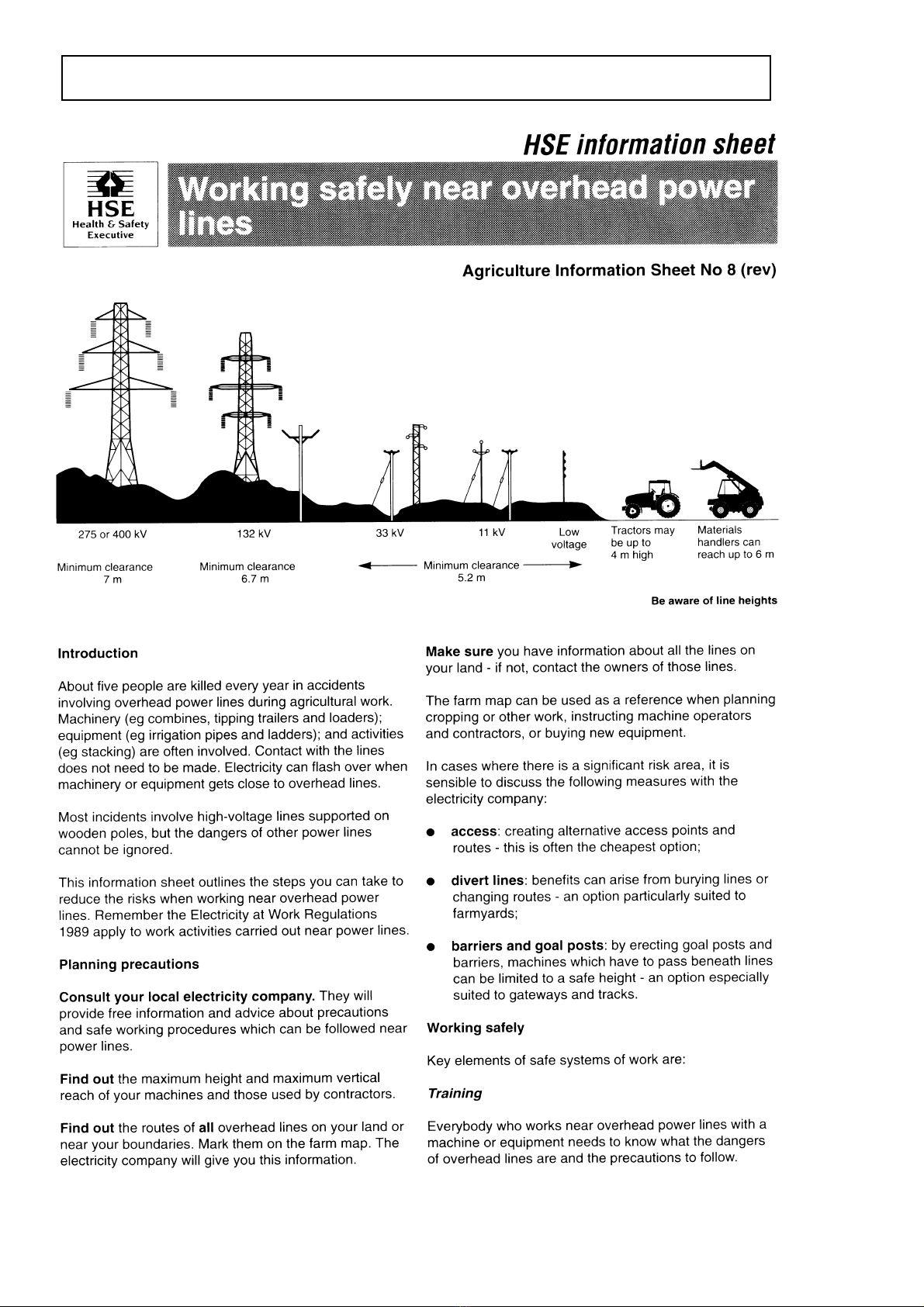
Working safely near
overhead power lines 1.5
INSTALLATION
Overview 1.7
Tractor Suitability 1.7
Attaching the Planter to the Tractor 1.7
OPERATION
Planting 1.9
Depth Control 1.9
Land Wheels 1.10
Row Centres 1.11
Tipping Hopper 1.12
Hopper Belts 1.13
Singulating Belts 1.14
Trough Belt 1.14
Seed Placement Belt 1.15
Openers 1.15
Soil Retention Panels 1.16
Bed Shaper Control Linkage 1.16
Ridger Bodies 1.17
2-Row Front Ridger 1.17
Bed Forming Board 1.18
Multi-Adjustable Moulding Board 1.18
Control System 1.19
Setting Up the Control System 1.20
Calibrating the Control System 1.21
Manual Hydraulic Depth Control 1.22
Automatic Hydraulic Depth Control 1.22
Hopper Belt Speed and Delay 1.23
Singulating Belt Speed and Delay 1.23
Trough Belt and
Seed Placement Belt Speed 1.24
Seed Warning Delay 1.24
Screen Brightness 1.24
Statistics 1.24
Diagnostics 1.24
Converting from 3-Rows to 2-Rows 1.25
Hydraulic Ram Speed Adjustment 1.25
Calibrating the Hydraulic Valves 1.25
MAINTENANCE
Belt Tension 1.26
Drive Chain Tension 1.27
Sensor Adjustment 1.27
Electrical System Maintenance 1.28
Hydraulic System Maintenance 1.28
Lubrication 1.29
Daily Maintenance 1.30
Weekly Maintenance 1.30
Annual Maintenance 1.30
Out of Season Storage 1.31
SPECIFICATION
Machine Dimensions 1.32
Machine Weight 1.32
Technical Data 1.32
Nut / Bolt Tightening Torque 1.32

Introduction to the Handbook
This handbook provides the information for the operation, adjustment and
maintenance of your STANDEN ZENO Potato Planter. To enable you to achieve the
best results from the machine, the manufacturer recommends that you read the
handbook thoroughly prior to using the machine for the first time.
Record below the details of your machine.
Dealers name...............................................................................…………….
Address......................................................................................................
.................................................................................................................
Telephone number.................................................................................…….
Machine serial number...............................................................................…
Date purchased............................................................................................
Date started work........................................................................................
This symbol indicates important safety messages within this handbook.
When you see this symbol, be alert to the possibility of injury to yourself
or others and/or damage to the machine and carefully read the
message that follows.
Throughout this handbook the terms 'front', 'rear', 'left-hand' (LH) and 'right-hand'
(RH) are derived from the tractor driver’s position facing forward in the normal
direction of travel.
Adjustments to the machine may have to be made singly or in combination according
soil conditions. Always allow the machine to settle to a new setting before making
further adjustments.
Recommended lubrication and maintenance instructions are included in this
handbook and if followed will help to keep the machine in a safe working condition.
Warranty
Should the machine suffer any faults or defects within the warranty period, please
contact your dealer. The warranty shall be effective only if the dealer is informed of
any such defect as soon as practicable upon discovery.
1.1
INTRODUCTION

Replacement Parts
Recommended replacement parts are designed for your machine and have the full
backing of the warranty. Only when recommended parts are used can responsibility
be considered under the terms of the warranty.
The rear section of this handbook contains lists of spare parts available through your
Standen Agents. Each illustration shows a complete unit or assembly in exploded
form. Standen's policy of continual product development means that components or
even complete assemblies are redesigned from time to time. Where possible the
modifications are shown in the remarks column.
The first printing of each page in the spare parts section is identified as issue 1 at the
foot of the page. When a complete unit or assembly has been redesigned the
appropriate pages are revised and printed as issue 2. The revised pages are filed
behind the existing issue so that a complete modification history is gradually built up.
When using an illustration and parts list it is essential that both are of the same issue.
Always quote the full serial number of your machine when ordering spare
parts.
INTRODUCTION
1.2

Safety
The STANDEN ZENO Potato Planters have been designed to comply with current
Safety Regulations. However, as with all machinery there will be inherent dangers
whilst operating and carrying out maintenance on the machine. The following list of
precautions should therefore be brought to the attention of all persons operating and
working on the machine. The list is not exhaustive. All machinery is potentially
dangerous and great care must be exercised by the operators at all times. Standen
Engineering Limited will not accept liability for damage or injury caused by their
products except when such liability is specifically imposed by English statute.
The machine must never be operated by untrained personnel or
children.
The tractor must be of a suitable size to lift the implement safely. This
may entail the fitting of front weights to counterbalance the machine
when in the raised position.
Always check that the machine has been correctly mounted to the
tractor before setting off on operations and the stabilizers are correctly
set.
Never set machinery in motion before ensuring that everyone in the
vicinity is aware of your intentions.
Never allow children or animals in the vicinity where machines are
working and never allow anyone to ride on the machine.
Never attempt to fit drive chains or drive belts to the machine while the
drive sprockets or pulleys are in motion.
Normal safe working procedures should be adopted at all times.
Reduce speed when transporting the machine on sloping ground.
Do not work on ground where there is a possibility of overturning or
across steep slopes.
The working area should be kept clear and free of obstructions at all
times. Be alert for hidden obstructions. Should the machine hit an
obstruction, stop and check for damage before proceeding.
Wear substantial or proper safety footwear. Avoid loose clothing near
moving parts. Wear gloves when handling the implement or parts with
sharp edges.
Before carrying out any work on the machine, lower the machine to the
ground, switch off the tractor engine, apply the handbrake, remove the
ignition key. Never work on or pass under the machine when it is raised
on the tractor hydraulic linkage.
1.3
SAFETY PRECAUTIONS

When left free standing i.e. not attached to the tractor, the machine
must be on level ground.
The operator must not leave the tractor seat until the machine has been
lowered to the ground, the tractor engine switched off, the handbrake
applied and the ignition key removed.
Never reverse or turn unless the machine is in the raised position.
All guards, covers, warning transfers and safety devices must be
correctly fitted and operable at all times.
Inspect the machine on a regular basis and replace damaged or worn
parts as necessary.
Never operate the machine in a state of disrepair.
Only transport the machine at a speed suitable to the prevailing
conditions. Be aware of the weight and overall length of the machine at
all times.
When in transport keep the hopper empty. Always fill the hopper in the
field. Transporting with a full hopper causes strain on both planter and
tractor and will pack the potatoes in the hopper causing ‘bridging’ when
planting commences.
Always ensure road lights are clean and in good working order.
Always lock the raised hopper with the stays before working
underneath. Always unlock the hopper again before lowering.
Always use mechanical or additional help when lifting heavy parts.
Regularly check hydraulic hoses for chafing or damage and replace as
necessary.
Care must be taken when carrying out any work on the hydraulic
system. Even when stopped and disconnected from the tractor, residual
pressure will exist within the hydraulic system. Therefore, before
commencing any work on the hydraulics ensure that the system is free
of residual pressure.
Safety is the responsibility of the persons working with this
machine. Think "safety" at all times. Read and remember the
contents of this handbook.
SAFETY PRECAUTIONS
1.4
1.5
SAFETY PRECAUTIO
NS

SAFETY PRECAUTIONS
1.6
Overview
STANDEN ZENO 2-row and 3-row tractor mounted planters are designed to plant
potatoes with extreme gentleness and accuracy in either standard planting or bed
work.
Tractor Suitability
The ZENO planter is suitable for CAT 2 and CAT 3 tractors of 75 Kw (100 bhp)
minimum with open-centre, closed-centre or load-sensing hydraulic systems..
The tractor must be of a suitable size to lift the implement safely. This
may entail the fitting of front weights to counterbalance the machine
when in the raised position.
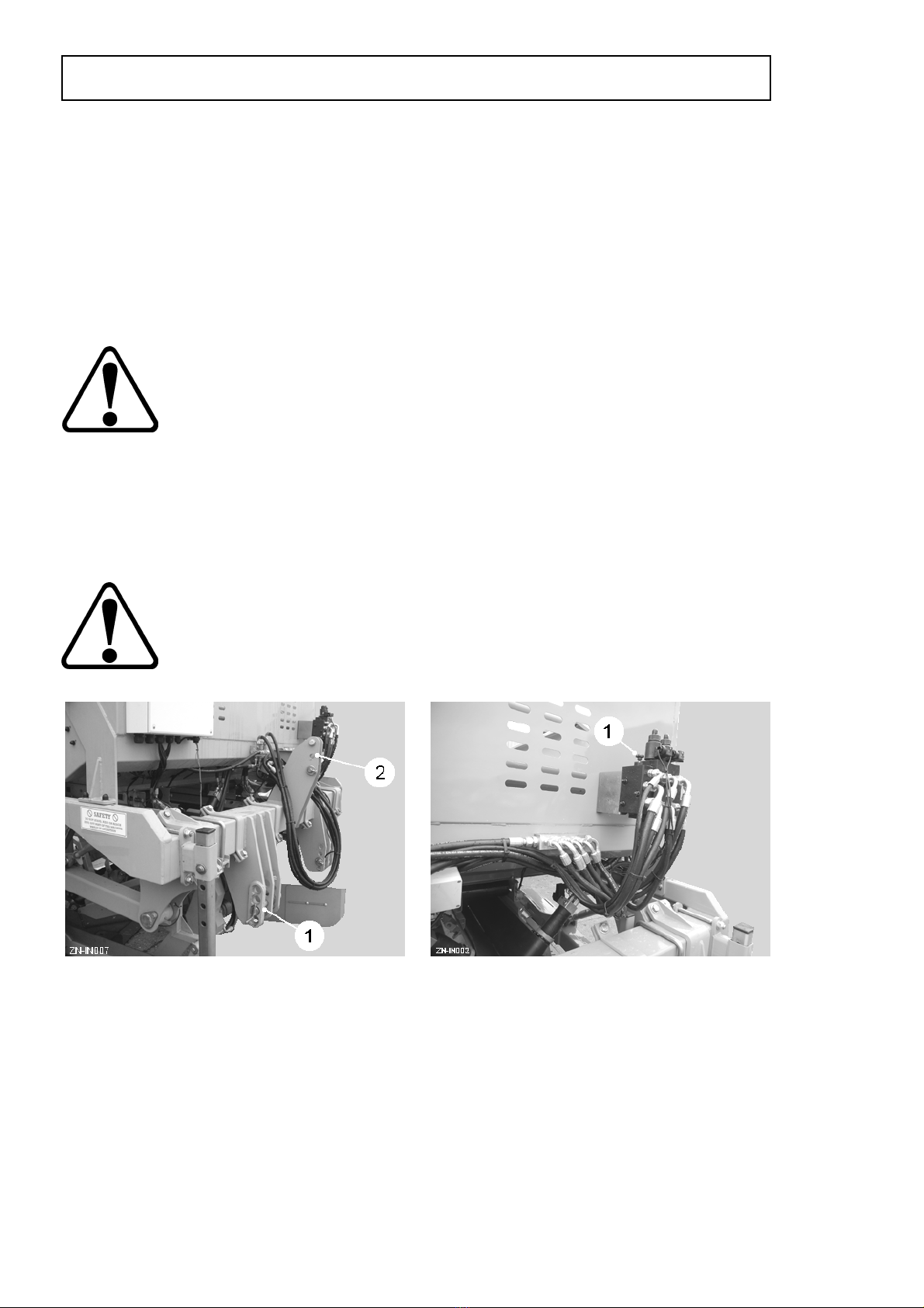
Attaching the Planter to the Tractor
Reverse the tractor up to the planter and engage the 3-point linkage lower arms on
the bottom lift pins (item 1, fig 1). The arm stabilisers must be set to ensure the
planter runs central to the tractor. Fit the top link in one of the holes (item 2, fig 1) and
adjust to level the planter.
When fitting to the tractor ensure the planter is standing on firm level
ground. The operator should have read and understood the tractor
operators manual prior to attaching the machine and putting into work.
Set the planter valve bank to match the tractor hydraulic system. For closed-centre
and load-sensing systems, turn the screw (item 1, fig 2) clockwise until fully in. For
open-centre systems, turn the screw anti-clockwise until fully out.
Connect the hydraulic pressure hose (red) to the tractor constant supply port.
Connect the hydraulic return hose (blue) to the tractor return port.
Connect the ¼” load sensing hose (if required) to the tractor L/S outlet.
1.7
INSTALLATION
Fig 1 Fig 2
Mount the control console in a position where it is comfortable to operate when
seated. An adjustable suction mount is fitted to attach the console to the side window
of the tractor.
Care should be taken to ensure the control box does not obstruct driver
visibility and access to the tractor controls.
Connect the control lead between the planter and control console by routing it
through existing apertures in the tractor cab.
Ensure the plug and socket connections are clean and coupling pins undamaged
before connection, and that they are securely locked together.
The control console requires a 12v D.C. supply. A ‘D’ plug is fitted to the power lead
for connection to the tractor electrics. If the power becomes too low to operate the
planter it may be necessary to connect the lead directly to the tractor battery, blue
lead to negative (-) terminal and brown lead to positive (+) terminal.
Ensure the battery connections are made correctly to prevent damage
to the control system.
Finally, connect the road lights plug to the tractor 7-pin socket.
INSTALLATION
1.8

Planting
Careful planting is one of the pre-requisites for a good crop of high quality potatoes.
The potatoes should be planted in straight ridges without gaps and at a correct and
even depth. This is achieved when, at the beginning of planting, the functions of the
planter and the different adjustments are carefully studied.
The seed potatoes used can vary a great deal (i.e. different varieties, shape, size,
number of sprouts, skin quality etc.) and the planter must be adjusted accordingly.
See ‘Calibrating the Control System’.
Depth Control
The seed planting depth is determined by the height of the openers (item 1, fig 3)
relative to the land wheels (item 1, fig 4). The depth control can be either manual or
hydraulic.
On machines with manual depth control, the depth is set by the top links (item 2, fig
4). Shortening the top links will lower the openers relative to the wheels thus
increasing the planting depth. Always adjust both wheels equally.
On machines with hydraulic depth control the top link is replaced by a hydraulic ram
actuated via the control console.
An automatic depth control sensor can also be fitted to ensure planting depth is
maintained irrespective of the contours of the bed.
1.9
OPERATION
Fig 4Fig 3

Land Wheels
The land wheels can be either fixed or steerable. A proximity sensor fitted to the RH
wheel axle monitors the forward speed of the planter.
On machines with steerable wheels, a wheel indicator is fitted to assist the operator.
The land wheels must be set to straddle the rows.
The distance between the LH and RH wheels can be set between 68” (172cm) to 80”
(203cm) on a 2-row machine, and between 72” (183cm) to 80” (203cm) on a 3-row
machine.
To adjust the land wheels:
With the tractor and planter outfit on firm, level ground, raise the planter wheels clear
of the ground and place supports under the front beam (item 3, fig 4) and rear beam
(item 4, fig 4).
WARNING: Never work under the machine when raised on the
tractor 3-point linkage. Always use additional supports.
Loosen the axle mounting clamps (item 1, fig 5) and slide the wheel unit out to the
desired position symmetrical about the centre of the machine. Finally, retighten the
clamps.
OPERATION
1.10
Fig 5

Row Centres
Row centres can be set between 30” (76cm) to 40” (102cm) on a 2-row machine, and
between 16” (41cm) to 18” (46cm) on a 3-row machine.
WARNING: Always lock the raised hopper with the stays (item 2,
fig 8) before working underneath (see tipping hopper).
To adjust row centres:
1. With the planter on firm, level ground, raise the planter on its land wheels until
the openers (item 1, fig 3) are clear of the ground.
2. Place supports under the front and rear beams (item 3 & 4, fig 4) to stabilise the
machine.
3. Fully raise the tipping hopper and fit the stays (item 2, fig 8).
4. Loosen the opener unit front clamps x2 (item 1, fig 6) and the rear clamp plate
(item 2, fig 6).
5. Loosen the moulding board / ridger tool bar mounting brackets x2 (item 3, fig 6).
6. Loosen the hopper filler plate lug bolts x4 (item 1, fig 7), the slot bolts x4 (item 2,
fig 7) and the mounting bolts x2 (item 3, fig 7).
7. Using mechanical assistance, slide the complete opener unit out to the desired
position symmetrical about the centre of the machine.
8. Depending on row centres, it may be necessary to remove the filler plate
mounting bolts (item 3, fig 7) and position them in a different hole in the hopper
panels.
9. Repeat for the other opener unit.
10. Finally, retighten all clamps and bolts
1.11
OPERATION
Fig 6 Fig 7

Tipping Hopper
The rear section of the tipping hopper (item 1, fig 8) is designed to gently feed the
potatoes into the hopper belts. Sensors can be fitted inside the hopper to detect the
level of seed above the hopper belt feed area. On automatic mode the sensors raise
the rear section of the hopper automatically.
The stays (item 2, fig 8) are provided to lock the hydraulic rams (item 3, fig 8) in the
open position when working under the hopper. The hopper should be empty when
performing this operation.
WARNING: Always lock the raised hopper with the stays (item 2,
fig 8) before working underneath.
To lock the hopper in the raised position:
1. Raise the hopper fully.
2. Remove the pin (item 4, fig 8) and lower the stay (item 2, fig 8) down over the
piston rod (item 5, fig 8).
3. Insert the pin (item 4, fig 8) into the hole (marked A) fitting it under the piston
rod and secure it with the ‘R’ clip.
Always unlock and reset the stays (item 2, fig 8) before lowering
the hopper. Failure to observe this caution may cause serious
damage to the machine.
OPERATION
1.12
Fig 8

Hopper Belts
The hopper belt (item 1, fig 10) conveys the seed potatoes from the hopper to the
singulating belts (item 2, fig 10). The regulator plate (item 1, fig 11) should be set to
keep a single layer of seed covering the hopper belt. Lowering the regulator plate too
much could result in ‘bridging’ and may cause a blockage. To adjust pull out the knob
(item 2, fig 11) and relocate the knob plunger into a different slot in the index plate.
The sensor (item 3, fig 10), via the motor ON/OFF valve (item 4, fig 10), controls the
amount of seed deposited onto the singulating belts (item 2, fig 10). The amount
should be sufficient to create a continuous, single line of potatoes on the singulating
belts. To achieve this, raise / lower the sensor arm (item 5, fig 10). Moving the sensor
down closer to the singulating belts will cause the hopper belt to stop sooner thus
reducing the seed quantity.
1.13
OPERATION
Fig 10
Fig 11
Fig 9
Singulating Belts
The singulating belts (item 2, fig 10) consist of one fast belt and one slow belt
arranged in a V-format. The action of the fast and slow belts sorts the potatoes into a
continuous, single line before feeding them onto the trough belt. The belts on the RH
unit are each fitted with a proximity sensor (item 1, fig 12) which monitors their
speed.
The sensor (item 2, fig 12), via the motor ON/OFF valves (item 3, fig 12), controls the
flow of seed. A continuous, single line of potatoes should be presented to the trough
belt. To achieve this the sensor can be adjusted for position and range.
To adjust the position, loosen the clamp bolt and slide the sensor along the support
bar (item 4, fig 12). The sensor should be positioned to allow a row of seed to build
up in front of the seed placement belt.
The rubber curtain (item 5, fig 12) is designed to restrict the flow of singulated seed
to the trough belt. The curtain is raised / lowered by loosening the locking knob (item
6, fig 12) and rotating the curtain mounting. Do not restrict the flow too much as this
can result in misses when planting.
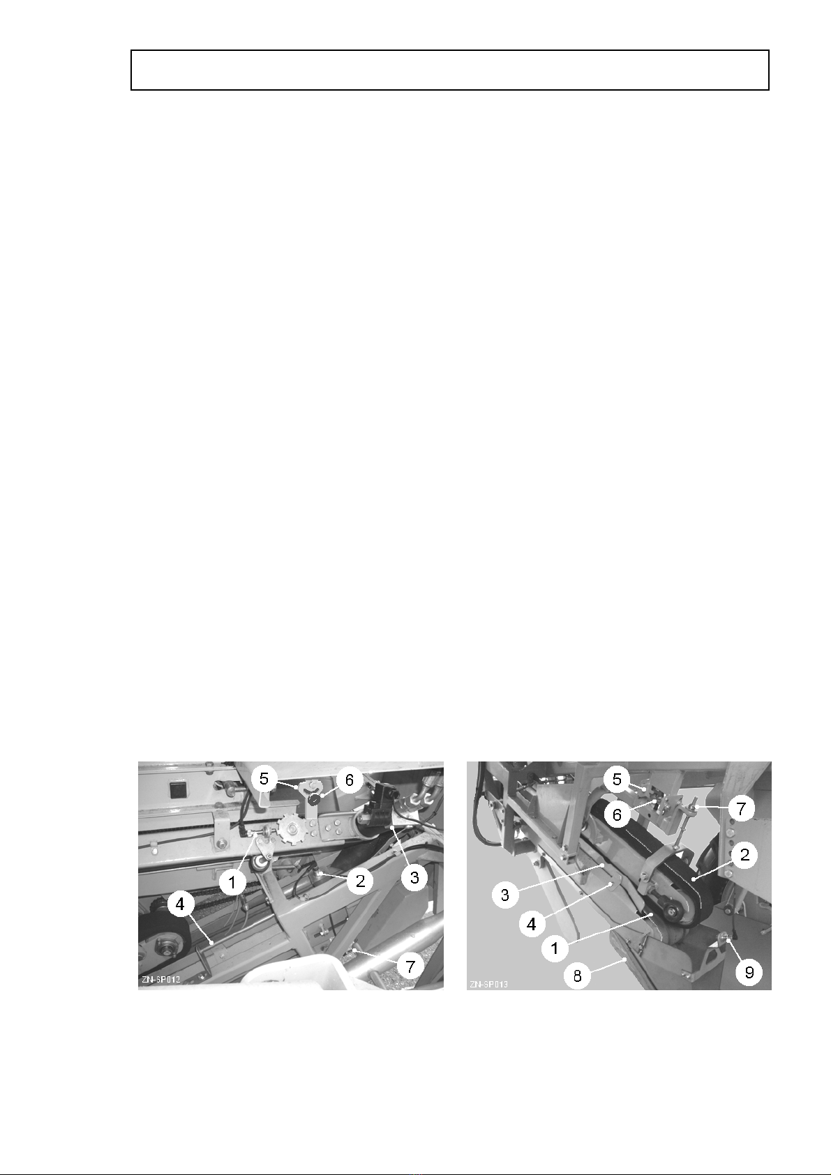
Trough Belt
The trough belt (item 1, fig 13) and seed placement belt (item 2, fig 13) work together
to deliver the row of seed potatoes to the openers. The sensor (item 7, fig 12)
monitors the speed of the belts which, along with the forward speed of the planter,
ensures even spacing of the seed in the ground.
The sides of the trough belt are angled upwards by the extension panels (item 3, fig
13) creating a trough that keeps the potatoes centred. The panels are adjustable to
create different width troughs depending on seed size and should be set to prevent
one potato overtaking another which could result in ‘doubles’. To adjust, loosen the
bolts x3 (item 4, fig 13) and slide the extension panels to the required position.
OPERATION
1.14
Fig 12
Fig 13

Seed Placement Belt
The height and angle of the seed placement belt (item 2, fig 13) relative to the trough
belt (item 1, fig 13) should be set to allow the pintle fingers to grip the seed. If set too
low, the belt may crush the seed. Conversely, setting the belt too high will allow the
seed to roll out without any control.
To adjust the height of the placement belt, loosen the mounting bolts x4 (item 5, fig
13) and turn the adjuster nut (item 6, fig 13) clockwise to raise unit or anti-clockwise
to lower the unit.
The throat angle should be set to give the potatoes a lead-in. An angle of
approximately 5°relative to the trough belt is usually sufficient. To adjust the angle,
turn the locknuts (item 7, fig 13).
Openers
The stainless steel openers (item 8, fig 13) produce a furrow in the bed ready to
accept the seed. The height of the front wear point is adjustable to produce a deeper
furrow. The sensor (item 9, fig 13) detects the potatoes as they fall into the opener.
1.15
OPE
RATION
This manual suits for next models
2
Table of contents
Other Standen Farm Equipment manuals

Standen
Standen T2 User manual

Standen
Standen T2 Service manual

Standen
Standen POWAVATOR 400 User manual

Standen
Standen T2 Service manual

Standen
Standen BX Series User manual

Standen
Standen SP Series User manual

Standen
Standen POWAVATOR 400 Service manual

Standen
Standen TSP 1900 Service manual

Standen
Standen SP Series User manual

Standen
Standen SP Series User manual


